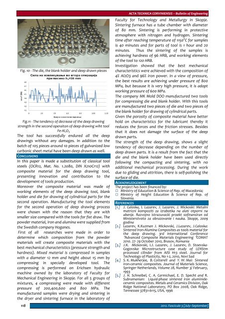
Fig. 10 ‐ The die, the blank holder and deep drawn piecesFig.11 ‐ The tendency of decrease of the deep drawingstrength in the second operaiton of deep drawing wiht toolFe‐Al 2 O 3The tool has successfully endured all the deepdrawings without any damages. In addition to thebatch of 105 pieces around 10 pieces of galvanized lowcarbonic sheet metal have been deep drawn as well.CONCLUSIONSIn this paper is made a substitution of classical toolsteels (OCR12, Mat. No. 1.2080, DIN X210Cr12) withcomposite material for the deep drawing tool,presenting innovation and contribution to thedevelopment of tools production.Moreover the composite material was made ofworking elements of the deep drawing tool, blankholder and die for drawing of cylindrical parts for thesecond operation. Manufacturing the tool elementsfor the second operation of deep drawing processwere chosen with the reason that they are withsmaller size compared with the tools for fist draw. Thepowder material, iron and alumina were supplied fromthe Swedish company Hoganes.First of all researches were made in order todetermine which composition from the powdermaterials will create composite materials with thebest mechanical characteristics (pressure strength andhardness). Mixed material is compressed in sampleswith a diameter 12 mm and height about 15 mm bycompressing in specially developed tool. Thecompressing is performed on Erichsen hydraulicmachine owned by the laboratory of Faculty forMechanical Engineering in Skopje. For all 5 groups ofmixtures, 4 compressing were made with differentpressure of 200,400,600 and 800 MPa. Themanufactured samples were drying and sintering inthe dryer and sintering furnace in the laboratory of118ACTA TECHNICA CORVINIENSIS – Bulletin of EngineeringFaculty for Technology and Metallurgy in Skopje.Sintering furnace has a tube chamber with diameterof 80 mm. Sintering is performing in protectiveatmosphere with nitrogen and hydrogen. Sinteringtime after reaching temperature of 1150 0 C for samplesis 40 minutes and for parts of tool is 1 hour and 20minutes. Thus the sintering of the samples isachieving hardness of 96 HRB, and working elementsof the tool to 120 HRB.Investigation showed that the best mechanicalcharacteristics were achieved with the composition of4% Al2O3 and 96% iron power. In a view of pressure,the best results are achieving under pressure of 800MPa, but because it is very high pressure, it is adoptworking pressure of 600 MPa.The company MK Mold DOO manufactured two toolsfor compressing die and blank holder. With this toolsare manufactured two pieces of die and two pieces ofthe blank holder for drawing of cylindrical parts.Given the porosity of composite material have betterhold on characteristics for the lubricant thereby itreduces the forces and the friction stresses. Besidesthat it does not damage the surface of the deepdrawn parts.The strength of the deep drawing, shows a slighttendency of decrease depending on the number ofdeep drawn parts. It is a result from the fact that thedie and the blank holder have been used directlyfollowing the compacting and sintering, with noadditional mechanical processing. During the workdue to gliding and attrition, there is self‐polishing thesurface of die.ACKNOWLEDGEMENTThe project has been financed by: Ministry of Education & Science of Rep. of Macedonia; Ministry of Height Education & Science of Rep. ofSlovenia.REFERENCES[1.] J. Caloska, I. Lazarev, J. Lazarev, J. Mickoski: Metalnimatricni kompoziti za izrabotka na alati otporni naabenje. Razvojno istrazuvacki proekt sofinansiran odMinisterstvoto za obrazovanie i nauka. Skopje, 2009godina[2.] Lazarev, K.Kuzman J. Mickovski, J.Lazarev, J.Caloska:Sintered Iron‐Alumina Composites as tools material forthe deep drawing. 3rd International Conference″Advanced Composite Materials Engineering ″COMAT2010. 27‐ 29 October 2010, Brasov, Romania[3.] Ј.К. Mickovski, I.Ј. Lazarev, Ј. Lazarev, D. Stoevska‐Gogovska: Microstructure case study of LENStmprocessed cilinder from AISI H13 steel. Journal forTechnology of Plasticity, No 1‐2, 2010, Novi Sad[4.] S. K. Mukherjee, B. Cotterell and Y. W. Mai: Sinterediron‐ceramic composites. Journal of Materials Science,Springer Netherlands, Volume 28, Number 3/ February,1993[5.] J. H. Schneibel, C. A. Carmichael, E. D. Specht and R.Subramanian: Liquid‐phase sintered iron aluminideceramiccomposites. Metals and Ceramics Division, OakRidge National Laboratory, PO Box 2008, Oak Ridge,Tennessee 37831‐6115, USA, 19962012. Fascicule 3 [July–September]
1. Georgeta Emilia MOCUȚA, 2. Mihaela POPESCU, 3. Ioan Dănuț DANTHE BEST WAY OF WORKING SPACE ROBOT WHICH EQUIPS AFLEXIBLE MANUFACTURING CELL COMPONENT OF WELDED IN RAILFIELD1‐2. POLITEHNICA UNIVERSITY OF TIMISOARA, ROMANIA3. SOCIETATEA NAȚIONALĂ TRANSPORT FEROVIAR MARFĂ, "CFR MARFA"‐SA SUCURSALA TIMISOARA, ROMANIAABSTRACT: The industrial robot acts on its operating space under different shapes, namely by manipulating parts, byexecuting processing technological operations, by measuring specific parameters of products or even of the operatingspace etc. Many applications and functions performed by a robot reveal an essential characteristic, namely their versatility.Studying the movement of a robot consists of a single well‐defined problem but a collection of several problems that aremore or less than one other option. Exemplification was performed using MSC NASTRAN program.KEYWORDS: industrial robot, operating space, movement of a robot, exemplificationINTRODUCTIONThe industrial robot acts on its operating space underdifferent shapes, namely by manipulating parts, byexecuting processing technological operations, bymeasuring specific parameters of products or even ofthe operating space etc.Many applications and functions performed by a robotreveal an essential characteristic, namely theirversatility.Versatility defined as the robot's physical ability toperform various functions and to take various actionsin a given technological application is closely related tothe structure and mechanical ability of the robot,which in turn determines the configuration of therobot workspace.Since the workspace of a robot has geometrydepending on components and structure of itsmechanisms, in this space the characteristic point ofthe robot must execute motions on trajectoriesimposed by obstacles to avoid collision. In a firstanalysis of a robot working space should not be dealtwith "obstacles" and can be utilized. "Obstacles" areoperating in the area of warehouses or other exhaustretrofit devices of flexible robotic cell in which allcomponents must interact.Trajectory through "obstacles" can be chosen so thatwe can avoid collisions with maximum probability.THE STUDYStudying the movement of a robot consists of a singlewell‐defined problem but a collection of severalproblems that are more or less than one other option.The robot is becoming a more autonomousmechanical system that increases the need forautomatic trajectory planning in its development.The simplest planning problem assumes that therobot is only moving object in space which does notpossess dynamic properties thus avoiding temporalproblems.It also considers that the robot does not come intocontact with surrounding objects, thus avoidingproblems of mechanical interaction.These considerations turn the physical planningproblem into a purely geometric problem.Furthermore it is considered that the robot is onlymoving rigid solid which is limited only by theobstacles.With these simplifications the basic problem ofplanning robot trajectories can be formulated asfollows: let’s consider A a single solid or rigid (robot) thatmoves in a Euclidean space W, called workspace,represented by Rn, n = 2 or 3; it's movement isnot limited by any restriction on kinematics. let’s consider B1,...,Bq fixed rigid objects(obstacles) distributed in well defined positionsin working space W; knowing the position and orientation, at baseline,the robot, and final finishing position andorientation of this workspace W, generate a pathspecifying a continuous sequence of positions andorientations of A starting from the initialconfiguration (position and orientation), avoidingthe contact with obstacles Bj and finishing in thefinal configuration (position and orientation)final;© copyright FACULTY of ENGINEERING ‐ HUNEDOARA, ROMANIA 119if such a path does not exist, ”error” must bereported.It is obvious that although the basic planning problemis super simplified it is still a difficult problem withmany solutions and direct extensions to morecomplicated issues.Objectively mobile object (the robot the characteristicpoint) in such a matter is referred to in the literatureas ”flying objects”.The basic problem involves the robot path planningthrough exactly the trajectory generated by theplanner. It is also assumed that both the geometryand robotics as well as obstacles positions are knownwith precision. In reality no planning problem meetsthese assumptions. Moreover, they control theirrobots and geometric patterns are not precise. Sincethe robot has no a priori information about the
- Page 2 and 3:
ACTA TECHNICA CORVINIENSIS- BULLETI
- Page 4 and 5:
ACTA TECHNICA CORVINIENSIS - Bullet
- Page 6 and 7:
ACTA TECHNICA CORVINIENSIS - Bullet
- Page 8 and 9:
Regional Editors from MALAYSIAAbdel
- Page 10 and 11:
Imre TIMÁRUniversity of Pannonia,
- Page 12 and 13:
Ioan MILOŞANTransilvania Universit
- Page 14 and 15:
Member from GREECENicolaos VAXEVANI
- Page 16 and 17:
ACTA TECHNICA CORVINIENSIS - Bullet
- Page 18 and 19:
ACTA TECHNICA CORVINIENSIS - Bullet
- Page 20 and 21:
ACTA TECHNICA CORVINIENSIS - Bullet
- Page 22 and 23:
two decades are seismically deficie
- Page 24 and 25:
ACTA TECHNICA CORVINIENSIS - Bullet
- Page 26 and 27:
ACTA TECHNICA CORVINIENSIS - Bullet
- Page 28 and 29:
The Euler ecuation about the condit
- Page 30 and 31:
ACTA TECHNICA CORVINIENSIS - Bullet
- Page 32 and 33:
examination centre of the Hungarian
- Page 34 and 35:
ACTA TECHNICA CORVINIENSIS - Bullet
- Page 36 and 37:
elieve that they are communicating
- Page 38 and 39:
converting the data also increases
- Page 40 and 41:
REFERENCES[1.] Bhavyesh Divecha, Aj
- Page 42 and 43:
In addition, API (Application Progr
- Page 44 and 45:
The new protocol has to be implemen
- Page 46 and 47:
compressor, the now hot and highly
- Page 48 and 49:
Figure 7. Pressure ratio of evapora
- Page 50 and 51:
Physical data model (MFD) is obtain
- Page 52 and 53:
The new project which now includes
- Page 54 and 55:
Figure 3. Materials evolutionThe pr
- Page 56 and 57:
(GPa) and weight used in the textil
- Page 58 and 59:
ACTA TECHNICA CORVINIENSIS - Bullet
- Page 60 and 61:
ACTA TECHNICA CORVINIENSIS - Bullet
- Page 62 and 63:
A machine vision‐guided plant sen
- Page 64 and 65:
During the experiment, non‐unifor
- Page 66 and 67:
espectively velocities hodograph (v
- Page 68 and 69: generation and thermal‐diffusion
- Page 70 and 71: 70(Pr−1)=bGm( R −cPr)( − M+c
- Page 72 and 73: 72Figure 12: Sherwood Number for di
- Page 74 and 75: ACTA TECHNICA CORVINIENSIS - Bullet
- Page 76 and 77: The hardware components offer the p
- Page 78 and 79: Markers 1 (t=‐60 ms) and 2 (t=‐
- Page 80 and 81: ACTA TECHNICA CORVINIENSIS - Bullet
- Page 82 and 83: compensation, apply dynamic control
- Page 84 and 85: A. Impact on transmission line prot
- Page 86 and 87: [12.] W.H. Zhang, S.J. Lee, M.S. Ch
- Page 88 and 89: Substituting equations (2), (3), (4
- Page 90 and 91: ACTA TECHNICA CORVINIENSIS - Bullet
- Page 92 and 93: the tribological experiment to simu
- Page 94 and 95: It is difficult to determine temper
- Page 96 and 97: ACTA TECHNICA CORVINIENSIS - Bullet
- Page 98 and 99: where: “ν ” represents the con
- Page 100 and 101: Figure 10. The velocity field in a
- Page 102 and 103: made on demand. In this type of pro
- Page 104 and 105: traditional MANET routing protocol
- Page 106 and 107: and classification,” In Journal o
- Page 108 and 109: ACTA TECHNICA CORVINIENSIS - Bullet
- Page 110 and 111: ACTA TECHNICA CORVINIENSIS - Bullet
- Page 112 and 113: ACTA TECHNICA CORVINIENSIS - Bullet
- Page 114 and 115: ACTA TECHNICA CORVINIENSIS - Bullet
- Page 116 and 117: equipped with tube made from stainl
- Page 120 and 121: desktop, it must be based on runtim
- Page 122 and 123: ACTA TECHNICA CORVINIENSIS - Bullet
- Page 124 and 125: database, which makes it possible t
- Page 126 and 127: technology - „Applied logistics
- Page 128 and 129: increase in one of the factors lead
- Page 130 and 131: ACTA TECHNICA CORVINIENSIS - Bullet
- Page 132 and 133: ACTA TECHNICA CORVINIENSIS - Bullet
- Page 134 and 135: ACTA TECHNICA CORVINIENSIS - Bullet
- Page 136 and 137: ACTA TECHNICA CORVINIENSIS - Bullet
- Page 138 and 139: ACTA TECHNICA CORVINIENSIS - Bullet
- Page 140 and 141: ACTA TECHNICA CORVINIENSIS - Bullet