Amendment No. 1 to MoRTH/CMVR/TAP-115/116
Amendment No. 1 to MoRTH/CMVR/TAP-115/116
Amendment No. 1 to MoRTH/CMVR/TAP-115/116

Create successful ePaper yourself
Turn your PDF publications into a flip-book with our unique Google optimized e-Paper software.
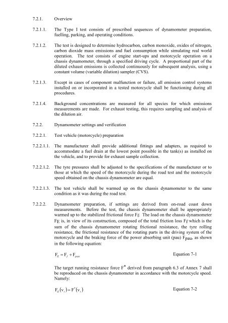
7.2.1. Overview7.2.1.1. The Type I test consists of prescribed sequences of dynamometer preparation,fuelling, parking, and operating conditions.7.2.1.2. The test is designed <strong>to</strong> determine hydrocarbon, carbon monoxide, oxides of nitrogen,carbon dioxide mass emissions and fuel consumption while simulating real worldoperation. The test consists of engine start-ups and mo<strong>to</strong>rcycle operation on achassis dynamometer, through a specified driving cycle. A proportional part of thediluted exhaust emissions is collected continuously for subsequent analysis, using aconstant volume (variable dilution) sampler (CVS).7.2.1.3. Except in cases of component malfunction or failure, all emission control systemsinstalled on or incorporated in a tested mo<strong>to</strong>rcycle shall be functioning during allprocedures.7.2.1.4. Background concentrations are measured for all species for which emissionsmeasurements are made. For exhaust testing, this requires sampling and analysis ofthe dilution air.7.2.2. Dynamometer settings and verification7.2.2.1. Test vehicle (mo<strong>to</strong>rcycle) preparation7.2.2.1.1. The manufacturer shall provide additional fittings and adapters, as required <strong>to</strong>accommodate a fuel drain at the lowest point possible in the tank(s) as installed onthe vehicle, and <strong>to</strong> provide for exhaust sample collection.7.2.2.1.2. The tyre pressures shall be adjusted <strong>to</strong> the specifications of the manufacturer or <strong>to</strong>those at which the speed of the mo<strong>to</strong>rcycle during the road test and the mo<strong>to</strong>rcyclespeed obtained on the chassis dynamometer are equal.7.2.2.1.3. The test vehicle shall be warmed up on the chassis dynamometer <strong>to</strong> the samecondition as it was during the road test.7.2.2.2. Dynamometer preparation, if settings are derived from on-road coast downmeasurements. Before the test, the chassis dynamometer shall be appropriatelywarmed up <strong>to</strong> the stabilized frictional force Ff. The load on the chassis dynamometerFE is, in view of its construction, composed of the <strong>to</strong>tal friction loss Ff which is thesum of the chassis dynamometer rotating frictional resistance, the tyre rollingresistance, the frictional resistance of the rotating parts in the driving system of themo<strong>to</strong>rcycle and the braking force of the power absorbing unit (pau) Fpau, as shownin the following equation:FE F FEquation 7-1fpauThe target running resistance force F * derived from paragraph 6.3 of Annex 7 shallbe reproduced on the chassis dynamometer in accordance with the mo<strong>to</strong>rcycle speed.Namely:FE*v F vi Equation 7-2i