

TeSys U LUTM Controller User Manual 03/2008 - Schneider Electric
TeSys U LUTM Controller User Manual 03/2008 - Schneider Electric
TeSys U LUTM Controller User Manual 03/2008 - Schneider Electric

You also want an ePaper? Increase the reach of your titles
YUMPU automatically turns print PDFs into web optimized ePapers that Google loves.
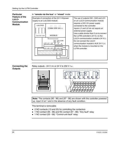
Setting Up the <strong>LUTM</strong> <strong>Controller</strong>ParticularFeature of theLULC•CommunicationModuleIn "remote via the bus" or "mixed" mode.Example of connection of the 24 Vsupply to an LULC<strong>03</strong>3 module:LULC<strong>03</strong>3Com OA1 OA3COMM ERR 24VLO1 LI1 LI2MODBUS24V 24VAux COM24VpowerThe use of outputs OA1, OA3 and LO1on an LULC• communication modulerequires a 24V power supplyconnected to the controller.Inputs LI1 and LI2 do not require anexternal power supply.Use a cable shorter than 5 cm to connectthe <strong>LUTM</strong> controller’s 24 V(-) to theLULC• communication module’s 24 V(-).Do not connect the LULC•communication module’s AUX 24 V (+)when the module is mounted on the<strong>LUTM</strong> controller.Connecting theOutputsRelay outputs - 24 V or 24 V to 250 V .Note: The contacts (95 - 96) and (97 - 98) are shown with the controller poweredup, input I.6 at 1 and in the absence of any fault condition.This terminal is removable.• 2 NO contacts (13 and 23) for controlling the contactors• 1 NO contact (95 - 96) and NC contact (97 - 98): "Any fault" relay• 1 NC contact (05 - 06): "Control-unit fault" relay.24 1743233 <strong>03</strong>/<strong>2008</strong>


