

TeSys U LUTM Controller User Manual 03/2008 - Schneider Electric
TeSys U LUTM Controller User Manual 03/2008 - Schneider Electric
TeSys U LUTM Controller User Manual 03/2008 - Schneider Electric

You also want an ePaper? Increase the reach of your titles
YUMPU automatically turns print PDFs into web optimized ePapers that Google loves.
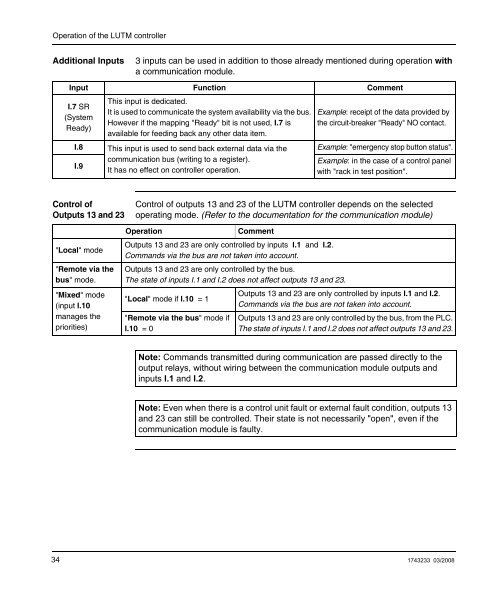
Operation of the <strong>LUTM</strong> controllerAdditional Inputs3 inputs can be used in addition to those already mentioned during operation witha communication module.Input Function CommentThis input is dedicated.I.7 SRIt is used to communicate the system availability via the bus. Example: receipt of the data provided by(SystemHowever if the mapping "Ready" bit is not used, I.7 is the circuit-breaker "Ready" NO contact.Ready)available for feeding back any other data item.I.8 This input is used to send back external data via the Example: "emergency stop button status".communication bus (writing to a register).Example: in the case of a control panelI.9It has no effect on controller operation.with "rack in test position".Control ofOutputs 13 and 23Control of outputs 13 and 23 of the <strong>LUTM</strong> controller depends on the selectedoperating mode. (Refer to the documentation for the communication module)"Local" mode"Remote via thebus" mode."Mixed" mode(input I.10manages thepriorities)OperationCommentOutputs 13 and 23 are only controlled by inputs I.1 and I.2.Commands via the bus are not taken into account.Outputs 13 and 23 are only controlled by the bus.The state of inputs I.1 and I.2 does not affect outputs 13 and 23."Local" mode if I.10 = 1"Remote via the bus" mode ifI.10 = 0Outputs 13 and 23 are only controlled by inputs I.1 and I.2.Commands via the bus are not taken into account.Outputs 13 and 23 are only controlled by the bus, from the PLC.The state of inputs I.1 and I.2 does not affect outputs 13 and 23.Note: Commands transmitted during communication are passed directly to theoutput relays, without wiring between the communication module outputs andinputs I.1 and I.2.Note: Even when there is a control unit fault or external fault condition, outputs 13and 23 can still be controlled. Their state is not necessarily "open", even if thecommunication module is faulty.34 1743233 <strong>03</strong>/<strong>2008</strong>


