Noise generated by cavitating single-hole and multi-hole orifices in ...
Noise generated by cavitating single-hole and multi-hole orifices in ...
Noise generated by cavitating single-hole and multi-hole orifices in ...

Create successful ePaper yourself
Turn your PDF publications into a flip-book with our unique Google optimized e-Paper software.
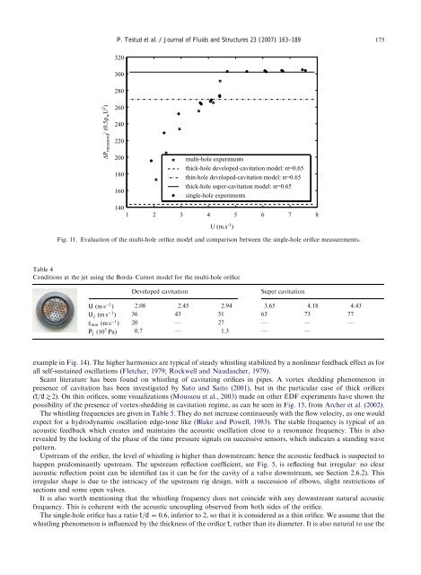
ARTICLE IN PRESSP. Testud et al. / Journal of Fluids <strong>and</strong> Structures 23 (2007) 163–189 175320300280∆P measured / (0.5ρ w U 2 )260240220200180160<strong>multi</strong>-<strong>hole</strong> experimentsthick-<strong>hole</strong> developed-cavitation model: α=0.65th<strong>in</strong>-<strong>hole</strong> developed-cavitation model: α=0.65thick-<strong>hole</strong> super-cavitation model: α=0.65<strong>s<strong>in</strong>gle</strong>-<strong>hole</strong> experiments1401 2 3 4 5 6 7 8U (m.s -1 )Fig. 11. Evaluation of the <strong>multi</strong>-<strong>hole</strong> orifice model <strong>and</strong> comparison between the <strong>s<strong>in</strong>gle</strong>-<strong>hole</strong> orifice measurements.Table 4Conditions at the jet us<strong>in</strong>g the Borda–Carnot model for the <strong>multi</strong>-<strong>hole</strong> orificeDeveloped cavitationSuper cavitationU ðms 1 Þ 2.08 2.45 2.94 3.65 4.18 4.43U j ðms 1 Þ 36 43 51 63 73 77c m<strong>in</strong> ðms 1 Þ 20 — 27 — — —P j ð10 5 PaÞ 0.7 — 1.3 — —example <strong>in</strong> Fig. 14). The higher harmonics are typical of steady whistl<strong>in</strong>g stabilized <strong>by</strong> a nonl<strong>in</strong>ear feedback effect as forall self-susta<strong>in</strong>ed oscillations (Fletcher, 1979; Rockwell <strong>and</strong> Naudascher, 1979).Scant literature has been found on whistl<strong>in</strong>g of <strong>cavitat<strong>in</strong>g</strong> <strong>orifices</strong> <strong>in</strong> pipes. A vortex shedd<strong>in</strong>g phenomenon <strong>in</strong>presence of cavitation has been <strong>in</strong>vestigated <strong>by</strong> Sato <strong>and</strong> Saito (2001), but <strong>in</strong> the particular case of thick <strong>orifices</strong>ðt=d\2Þ. On th<strong>in</strong> <strong>orifices</strong>, some visualizations (Moussou et al., 2003) made on other EDF experiments have shown thepossibility of the presence of vortex-shedd<strong>in</strong>g <strong>in</strong> cavitation regime, as can be seen <strong>in</strong> Fig. 15, from Archer et al. (2002).The whistl<strong>in</strong>g frequencies are given <strong>in</strong> Table 5. They do not <strong>in</strong>crease cont<strong>in</strong>uously with the flow velocity, as one wouldexpect for a hydrodynamic oscillation edge-tone like (Blake <strong>and</strong> Powell, 1983). The stable frequency is typical of anacoustic feedback which creates <strong>and</strong> ma<strong>in</strong>ta<strong>in</strong>s the acoustic oscillation close to a resonance frequency. This is alsorevealed <strong>by</strong> the lock<strong>in</strong>g of the phase of the time pressure signals on successive sensors, which <strong>in</strong>dicates a st<strong>and</strong><strong>in</strong>g wavepattern.Upstream of the orifice, the level of whistl<strong>in</strong>g is higher than downstream: hence the acoustic feedback is suspected tohappen predom<strong>in</strong>antly upstream. The upstream reflection coefficient, see Fig. 5, is reflect<strong>in</strong>g but irregular: no clearacoustic reflection po<strong>in</strong>t can be identified (as it can be for the cavity of a valve downstream, see Section 2.6.2). Thisirregular shape is due to the <strong>in</strong>tricacy of the upstream rig design, with a succession of elbows, slight restrictions ofsections <strong>and</strong> some open valves.It is also worth mention<strong>in</strong>g that the whistl<strong>in</strong>g frequency does not co<strong>in</strong>cide with any downstream natural acousticfrequency. This is coherent with the acoustic uncoupl<strong>in</strong>g observed from both sides of the orifice.The <strong>s<strong>in</strong>gle</strong>-<strong>hole</strong> orifice has a ratio t=d ¼ 0:6, <strong>in</strong>ferior to 2, so that it is considered as a th<strong>in</strong> orifice. We assume that thewhistl<strong>in</strong>g phenomenon is <strong>in</strong>fluenced <strong>by</strong> the thickness of the orifice t, rather than its diameter. It is also natural to use the