Noise generated by cavitating single-hole and multi-hole orifices in ...
Noise generated by cavitating single-hole and multi-hole orifices in ...
Noise generated by cavitating single-hole and multi-hole orifices in ...

You also want an ePaper? Increase the reach of your titles
YUMPU automatically turns print PDFs into web optimized ePapers that Google loves.
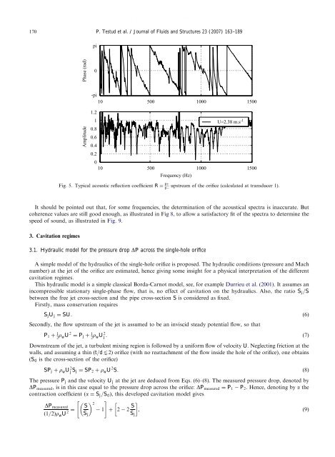
ARTICLE IN PRESS170P. Testud et al. / Journal of Fluids <strong>and</strong> Structures 23 (2007) 163–189piPhase (rad)0-pi10 500 1000 1500Amplitude1.21U=2.38 m.s -10.80.60.40.2010 500 1000 1500Frequency (Hz)Fig. 5. Typical acoustic reflection coefficient R ¼ pþpupstream of the orifice (calculated at transducer 1).It should be po<strong>in</strong>ted out that, for some frequencies, the determ<strong>in</strong>ation of the acoustical spectra is <strong>in</strong>accurate. Butcoherence values are still good enough, as illustrated <strong>in</strong> Fig 8, to allow a satisfactory fit of the spectra to determ<strong>in</strong>e thespeed of sound, as illustrated <strong>in</strong> Fig. 9.3. Cavitation regimes3.1. Hydraulic model for the pressure drop DP across the <strong>s<strong>in</strong>gle</strong>-<strong>hole</strong> orificeA simple model of the hydraulics of the <strong>s<strong>in</strong>gle</strong>-<strong>hole</strong> orifice is proposed. The hydraulic conditions (pressure <strong>and</strong> Machnumber) at the jet of the orifice are estimated, hence giv<strong>in</strong>g some <strong>in</strong>sight for a physical <strong>in</strong>terpretation of the differentcavitation regimes.This hydraulic model is a simple classical Borda-Carnot model, see, for example Durrieu et al. (2001). It assumes an<strong>in</strong>compressible stationary <strong>s<strong>in</strong>gle</strong>-phase flow, that is, no effect of cavitation on the hydraulics. Also, the ratio S j =Sbetween the free jet cross-section <strong>and</strong> the pipe cross-section S is considered as fixed.Firstly, mass conservation requiresS j U j ¼ SU. (6)Secondly, the flow upstream of the jet is assumed to be an <strong>in</strong>viscid steady potential flow, so thatP 1 þ 1 2 r wU 2 ¼ P j þ 1 2 r wU 2 j . (7)Downstream of the jet, a turbulent mix<strong>in</strong>g region is followed <strong>by</strong> a uniform flow of velocity U. Neglect<strong>in</strong>g friction at thewalls, <strong>and</strong> assum<strong>in</strong>g a th<strong>in</strong> ðt=dt2Þ orifice (with no reattachment of the flow <strong>in</strong>side the <strong>hole</strong> of the orifice), one obta<strong>in</strong>s(S d is the cross-section of the orifice)SP j þ r w U 2 j S j ¼ SP 2 þ r w U 2 S. (8)The pressure P j <strong>and</strong> the velocity U j at the jet are deduced from Eqs. (6)–(8). The measured pressure drop, denoted <strong>by</strong>DP measured , is <strong>in</strong> this case equal to the pressure drop across the orifice: DP measured ¼ P 1 P 2 . Hence, denot<strong>in</strong>g <strong>by</strong> a thecontraction coefficient ða ¼ S j =S d Þ, this developed cavitation model gives" #DP measuredð1=2Þr w U 2 ¼ S 2 1 þ 2 2 S , (9)S jS j