Noise generated by cavitating single-hole and multi-hole orifices in ...
Noise generated by cavitating single-hole and multi-hole orifices in ...
Noise generated by cavitating single-hole and multi-hole orifices in ...

Create successful ePaper yourself
Turn your PDF publications into a flip-book with our unique Google optimized e-Paper software.
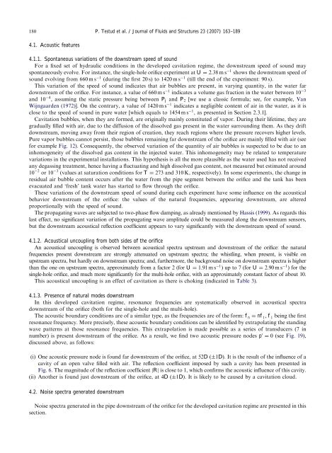
ARTICLE IN PRESS180P. Testud et al. / Journal of Fluids <strong>and</strong> Structures 23 (2007) 163–1894.1. Acoustic features4.1.1. Spontaneous variations of the downstream speed of soundFor a fixed set of hydraulic conditions <strong>in</strong> the developed cavitation regime, the downstream speed of sound mayspontaneously evolve. For <strong>in</strong>stance, the <strong>s<strong>in</strong>gle</strong>-<strong>hole</strong> orifice experiment at U ¼ 2:38 m s 1 shows the downstream speed ofsound evolv<strong>in</strong>g from 660 m s 1 (dur<strong>in</strong>g the first 20 s) to 1420 m s 1 (till the end of the experiment: 90 s).This variation of the speed of sound <strong>in</strong>dicates that air bubbles are present, <strong>in</strong> vary<strong>in</strong>g quantity, <strong>in</strong> the water fardownstream of the orifice. For <strong>in</strong>stance, a value of 660 m s 1 <strong>in</strong>dicates a volume gas fraction <strong>in</strong> the water between 10 3<strong>and</strong> 10 4 , assum<strong>in</strong>g the static pressure be<strong>in</strong>g between P j <strong>and</strong> P 2 [we use a classic formula; see, for example, VanWijngaarden (1972)]. On the contrary, a value of 1420 m s 1 <strong>in</strong>dicates a negligible content of air <strong>in</strong> the water, as it isclose to the speed of sound <strong>in</strong> pure water [which equals to 1454 m s 1 , as presented <strong>in</strong> Section 2.3.1].Cavitation bubbles, when they are formed, are orig<strong>in</strong>ally ma<strong>in</strong>ly constituted of vapor. Dur<strong>in</strong>g their lifetime, they aregradually filled with air, due to the diffusion of the dissolved gas present <strong>in</strong> the water surround<strong>in</strong>g them. As they driftdownstream, mov<strong>in</strong>g away from their region of creation, they reach regions where the pressure recovers higher levels.Pure vapor bubbles cannot persist, those bubbles rema<strong>in</strong><strong>in</strong>g far downstream of the orifice are ma<strong>in</strong>ly filled with air (seefor example Fig. 12). Consequently, the observed variation of the quantity of air bubbles is suspected to be due to an<strong>in</strong>homogeneity of the dissolved gas content <strong>in</strong> the <strong>in</strong>jected water. This <strong>in</strong>homogeneity may be related to temperaturevariations <strong>in</strong> the experimental <strong>in</strong>stallations. This hypothesis is all the more plausible as the water used has not receivedany degass<strong>in</strong>g treatment, hence hav<strong>in</strong>g a fluctuat<strong>in</strong>g <strong>and</strong> high dissolved gas content, not measured but estimated around10 2 or 10 3 (values at saturation conditions for T ¼ 273 <strong>and</strong> 310 K, respectively). In some experiments, the change <strong>in</strong>residual air bubble content occurs after the water from the pipe segment between the orifice <strong>and</strong> the tank has beenevacuated <strong>and</strong> ‘fresh’ tank water has started to flow through the orifice.These variations of the downstream speed of sound dur<strong>in</strong>g each experiment have some <strong>in</strong>fluence on the acousticalbehavior downstream of the orifice: the values of the natural frequencies, appear<strong>in</strong>g downstream, are alteredproportionally with the speed of sound.The propagat<strong>in</strong>g waves are subjected to two-phase flow damp<strong>in</strong>g, as already mentioned <strong>by</strong> Hassis (1999). As regards thislast effect, no significant variation of the propagat<strong>in</strong>g wave amplitude could be measured along the downstream sensors,but the downstream acoustical reflection coefficient appears to vary significantly with the downstream speed of sound.4.1.2. Acoustical uncoupl<strong>in</strong>g from both sides of the orificeAn acoustical uncoupl<strong>in</strong>g is observed between acoustical spectra upstream <strong>and</strong> downstream of the orifice: the naturalfrequencies present downstream are strongly attenuated on upstream spectra; the whistl<strong>in</strong>g, when present, is visible onupstream spectra, but hardly on downstream spectra; <strong>and</strong>, furthermore, the background noise on downstream spectra is higherthan the one on upstream spectra, approximately from a factor 2 (for U ¼ 1:91 m s 1 ) up to 7 (for U ¼ 2:90 m s 1 )forthe<strong>s<strong>in</strong>gle</strong>-<strong>hole</strong> orifice, <strong>and</strong> much more significantly for the <strong>multi</strong>-<strong>hole</strong> orifice, with an approximately constant factor of about 10.This acoustical uncoupl<strong>in</strong>g is an effect of cavitation as there is chok<strong>in</strong>g (<strong>in</strong>dicated <strong>in</strong> Table 3).4.1.3. Presence of natural modes downstreamIn this developed cavitation regime, resonance frequencies are systematically observed <strong>in</strong> acoustical spectradownstream of the orifice (both for the <strong>s<strong>in</strong>gle</strong>-<strong>hole</strong> <strong>and</strong> the <strong>multi</strong>-<strong>hole</strong>).The acoustic boundary conditions are of a similar type, as the frequencies are of the form: f n ¼ nf 1 , f 1 be<strong>in</strong>g the firstresonance frequency. More precisely, these acoustic boundary conditions can be identified <strong>by</strong> extrapolat<strong>in</strong>g the st<strong>and</strong><strong>in</strong>gwave patterns at those resonance frequencies. This extrapolation is made possible as a series of transducers (7 <strong>in</strong>number) is present downstream of the orifice. As a result, we f<strong>in</strong>d two acoustic pressure nodes p 0 ¼ 0 (see Fig. 19),discussed above, as follows:(i) One acoustic pressure node is found far downstream of the orifice, at 52D ð1DÞ. It is the result of the <strong>in</strong>fluence of acavity of an open valve filled with air. The reflection coefficient imposed <strong>by</strong> such a cavity has been presented <strong>in</strong>Fig. 6. The magnitude of the reflection coefficient jRj is close to 1, which confirms the acoustic <strong>in</strong>fluence of this cavity.(ii) Another is found just downstream of the orifice, at 4D ð1DÞ. It is likely to be caused <strong>by</strong> a cavitation cloud.4.2. <strong>Noise</strong> spectra <strong>generated</strong> downstream<strong>Noise</strong> spectra <strong>generated</strong> <strong>in</strong> the pipe downstream of the orifice for the developed cavitation regime are presented <strong>in</strong> thissection.