Noise generated by cavitating single-hole and multi-hole orifices in ...
Noise generated by cavitating single-hole and multi-hole orifices in ...
Noise generated by cavitating single-hole and multi-hole orifices in ...

Create successful ePaper yourself
Turn your PDF publications into a flip-book with our unique Google optimized e-Paper software.
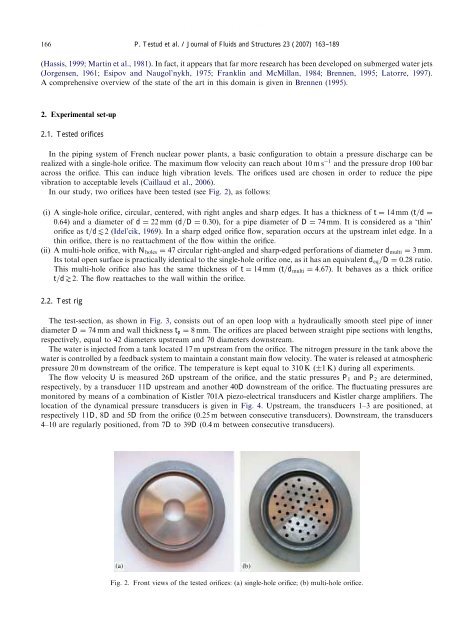
ARTICLE IN PRESS166P. Testud et al. / Journal of Fluids <strong>and</strong> Structures 23 (2007) 163–189(Hassis, 1999; Mart<strong>in</strong> et al., 1981). In fact, it appears that far more research has been developed on submerged water jets(Jorgensen, 1961; Esipov<strong>and</strong> Naugol’nykh, 1975; Frankl<strong>in</strong> <strong>and</strong> McMillan, 1984; Brennen, 1995; Latorre, 1997).A comprehensive overview of the state of the art <strong>in</strong> this doma<strong>in</strong> is given <strong>in</strong> Brennen (1995).2. Experimental set-up2.1. Tested <strong>orifices</strong>In the pip<strong>in</strong>g system of French nuclear power plants, a basic configuration to obta<strong>in</strong> a pressure discharge can berealized with a <strong>s<strong>in</strong>gle</strong>-<strong>hole</strong> orifice. The maximum flow velocity can reach about 10 m s 1 <strong>and</strong> the pressure drop 100 baracross the orifice. This can <strong>in</strong>duce high vibration levels. The <strong>orifices</strong> used are chosen <strong>in</strong> order to reduce the pipevibration to acceptable levels (Caillaud et al., 2006).In our study, two <strong>orifices</strong> have been tested (see Fig. 2), as follows:(i) A <strong>s<strong>in</strong>gle</strong>-<strong>hole</strong> orifice, circular, centered, with right angles <strong>and</strong> sharp edges. It has a thickness of t ¼ 14 mm ðt=d ¼0:64Þ <strong>and</strong> a diameter of d ¼ 22 mm ðd=D ¼ 0:30Þ, for a pipe diameter of D ¼ 74 mm. It is considered as a ‘th<strong>in</strong>’orifice as t=dt2 (Idel’cik, 1969). In a sharp edged orifice flow, separation occurs at the upstream <strong>in</strong>let edge. In ath<strong>in</strong> orifice, there is no reattachment of the flow with<strong>in</strong> the orifice.(ii) A <strong>multi</strong>-<strong>hole</strong> orifice, with N <strong>hole</strong>s ¼ 47 circular right-angled <strong>and</strong> sharp-edged perforations of diameter d <strong>multi</strong> ¼ 3 mm.Its total open surface is practically identical to the <strong>s<strong>in</strong>gle</strong>-<strong>hole</strong> orifice one, as it has an equivalent d eq =D ¼ 0:28 ratio.This <strong>multi</strong>-<strong>hole</strong> orifice also has the same thickness of t ¼ 14 mm ðt=d <strong>multi</strong> ¼ 4:67Þ. It behaves as a thick orificet=d\2. The flow reattaches to the wall with<strong>in</strong> the orifice.2.2. Test rigThe test-section, as shown <strong>in</strong> Fig. 3, consists out of an open loop with a hydraulically smooth steel pipe of <strong>in</strong>nerdiameter D ¼ 74 mm <strong>and</strong> wall thickness t p ¼ 8 mm. The <strong>orifices</strong> are placed between straight pipe sections with lengths,respectively, equal to 42 diameters upstream <strong>and</strong> 70 diameters downstream.The water is <strong>in</strong>jected from a tank located 17 m upstream from the orifice. The nitrogen pressure <strong>in</strong> the tank above thewater is controlled <strong>by</strong> a feedback system to ma<strong>in</strong>ta<strong>in</strong> a constant ma<strong>in</strong> flow velocity. The water is released at atmosphericpressure 20 m downstream of the orifice. The temperature is kept equal to 310 K ð1KÞ dur<strong>in</strong>g all experiments.The flow velocity U is measured 26D upstream of the orifice, <strong>and</strong> the static pressures P 1 <strong>and</strong> P 2 are determ<strong>in</strong>ed,respectively, <strong>by</strong> a transducer 11D upstream <strong>and</strong> another 40D downstream of the orifice. The fluctuat<strong>in</strong>g pressures aremonitored <strong>by</strong> means of a comb<strong>in</strong>ation of Kistler 701A piezo-electrical transducers <strong>and</strong> Kistler charge amplifiers. Thelocation of the dynamical pressure transducers is given <strong>in</strong> Fig. 4. Upstream, the transducers 1–3 are positioned, atrespectively 11D, 8D <strong>and</strong> 5D from the orifice (0.25 m between consecutive transducers). Downstream, the transducers4–10 are regularly positioned, from 7D to 39D (0.4 m between consecutive transducers).Fig. 2. Front views of the tested <strong>orifices</strong>: (a) <strong>s<strong>in</strong>gle</strong>-<strong>hole</strong> orifice; (b) <strong>multi</strong>-<strong>hole</strong> orifice.