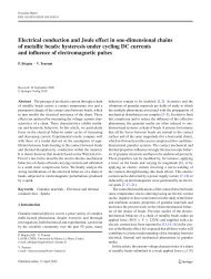
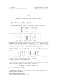
ARTICLE IN PRESS170P. Testud et al. / Journal of Fluids <strong>and</strong> Structures 23 (2007) 163–189piPhase (rad)0-pi10 500 1000 1500Amplitude1.21U=2.38 m.s -10.80.60.40.2010 500 1000 1500Frequency (Hz)Fig. 5. Typical acoustic reflection coefficient R ¼ pþpupstream of the orifice (calculated at transducer 1).It should be po<strong>in</strong>ted out that, for some frequencies, the determ<strong>in</strong>ation of the acoustical spectra is <strong>in</strong>accurate. Butcoherence values are still good enough, as illustrated <strong>in</strong> Fig 8, to allow a satisfactory fit of the spectra to determ<strong>in</strong>e thespeed of sound, as illustrated <strong>in</strong> Fig. 9.3. Cavitation regimes3.1. Hydraulic model for the pressure drop DP across the <strong>s<strong>in</strong>gle</strong>-<strong>hole</strong> orificeA simple model of the hydraulics of the <strong>s<strong>in</strong>gle</strong>-<strong>hole</strong> orifice is proposed. The hydraulic conditions (pressure <strong>and</strong> Machnumber) at the jet of the orifice are estimated, hence giv<strong>in</strong>g some <strong>in</strong>sight for a physical <strong>in</strong>terpretation of the differentcavitation regimes.This hydraulic model is a simple classical Borda-Carnot model, see, for example Durrieu et al. (2001). It assumes an<strong>in</strong>compressible stationary <strong>s<strong>in</strong>gle</strong>-phase flow, that is, no effect of cavitation on the hydraulics. Also, the ratio S j =Sbetween the free jet cross-section <strong>and</strong> the pipe cross-section S is considered as fixed.Firstly, mass conservation requiresS j U j ¼ SU. (6)Secondly, the flow upstream of the jet is assumed to be an <strong>in</strong>viscid steady potential flow, so thatP 1 þ 1 2 r wU 2 ¼ P j þ 1 2 r wU 2 j . (7)Downstream of the jet, a turbulent mix<strong>in</strong>g region is followed <strong>by</strong> a uniform flow of velocity U. Neglect<strong>in</strong>g friction at thewalls, <strong>and</strong> assum<strong>in</strong>g a th<strong>in</strong> ðt=dt2Þ orifice (with no reattachment of the flow <strong>in</strong>side the <strong>hole</strong> of the orifice), one obta<strong>in</strong>s(S d is the cross-section of the orifice)SP j þ r w U 2 j S j ¼ SP 2 þ r w U 2 S. (8)The pressure P j <strong>and</strong> the velocity U j at the jet are deduced from Eqs. (6)–(8). The measured pressure drop, denoted <strong>by</strong>DP measured , is <strong>in</strong> this case equal to the pressure drop across the orifice: DP measured ¼ P 1 P 2 . Hence, denot<strong>in</strong>g <strong>by</strong> a thecontraction coefficient ða ¼ S j =S d Þ, this developed cavitation model gives" #DP measuredð1=2Þr w U 2 ¼ S 2 1 þ 2 2 S , (9)S jS j
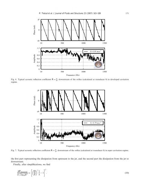
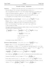
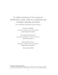
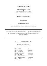
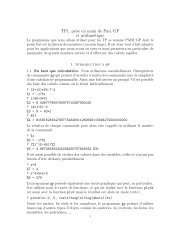
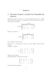
ARTICLE IN PRESSP. Testud et al. / Journal of Fluids <strong>and</strong> Structures 23 (2007) 163–189 171piPhase (rad)0-pi10 500 1000 1500Amplitude1.210.80.60.40.2010 500 1000 1500Frequency (Hz)U=1.91 m.s -1Fig. 6. Typical acoustic reflection coefficient R ¼ p pþdownstream of the orifice (calculated at transducer 8) <strong>in</strong> developed cavitationregime.piPhase (rad)0Amplitude-pi10 500 1000 15001.210.80.60.40.2010 500 1000 1500Frequency (Hz)U=3.75 m.s -1Fig. 7. Typical acoustic reflection coefficient R ¼ p pþdownstream of the orifice (calculated at transducer 8) <strong>in</strong> super cavitation regime.the first part represent<strong>in</strong>g the dissipation from upstream to the jet, <strong>and</strong> the second part the dissipation from the jet todownstream.F<strong>in</strong>ally, after simplifications, we f<strong>in</strong>dDP measuredð1=2Þr w U 2 ¼" # D 212 1d a. (10)