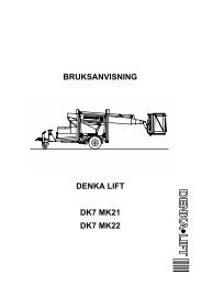
- Page 1: REPAIR MANUALSELF-PROPELLED SCISSOR
- Page 6: 21 Repair manual
- Page 9 and 10: Repair Manual10 - CORRECTIVE MAINTE
- Page 11 and 12: Repair manual 31 - GENERAL RECOMMEN
- Page 13 and 14: Repair manual 3To avoid all risk of
- Page 15 and 16: Repair manual 3NB:In the case of re
- Page 17 and 18: Repair manual 32 - SPECIFICATIONSel
- Page 19 and 20: 78590Repair manual 32.2 - SIZE2.2.1
- Page 21 and 22: Repair manual 32.4 - PRESSURE TABLE
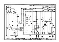
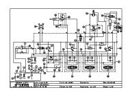
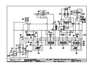
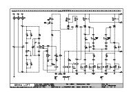
- Page 23 and 24: Repair manual 33 - WIRING DIAGRAM17
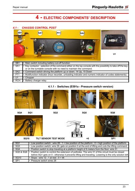
- Page 25 and 26: Repair manual 33.1.1 - Electric com
- Page 27: Repair manual 33.2.1 - Electric com
- Page 31 and 32: Repair manual 34.4 - END OF TRAVEL
- Page 33 and 34: Repair manual 34.7 - USING THE ON-B
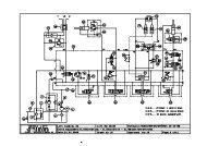
- Page 35 and 36: Repair manual 35 - HYDRAULIC DIAGRA
- Page 37 and 38: Repair manual 35.2.1 - Components l
- Page 39 and 40: Repair manual 36 - DESCRIPTION OF T
- Page 41 and 42: Repair manual 36.2 - MK4 HYDRAULIC
- Page 43 and 44: Repair manual 3FRONT VIEW37
- Page 45 and 46: Repair manual 36.2.1 - List of comp
- Page 47 and 48: Repair manual 36.3.4 - Speed select
- Page 49 and 50: Repair manual 3LoweringPotholes’
- Page 51 and 52: Repair manual 37 - MAINTENANCE7.1 -
- Page 53 and 54: Repair manual 37.4.2 - Maintenance
- Page 55 and 56: Repair manual 3REMINDER:All these f
- Page 57 and 58: Repair manual 38 - PREVENTIVE MAINT
- Page 59 and 60: SHEET P001PREVENTIVE MAINTENANCE SH
- Page 61 and 62: SHEET P002PREVENTIVE MAINTENANCE SH
- Page 63 and 64: SHEET P003PREVENTIVE MAINTENANCE SH
- Page 65 and 66: SHEET P004PREVENTIVE MAINTENANCE SH
- Page 67 and 68: Repair manual 39 - OPERATING INCIDE
- Page 69 and 70: Repair manual 39.1.3 - Travel syste
- Page 71 and 72: Repair manual 3AlarmcodeNumberoffla
- Page 73 and 74: Repair manual 39.2 - FAILURE DETECT
- Page 75 and 76: SHEET DP001FAILURE DETECTION FLOW C
- Page 77 and 78: SHEET DP002FAILURE DETECTION FLOW C
- Page 79 and 80:
SHEET DP003FAILURE DETECTION FLOW C
- Page 81 and 82:
SHEET DP003FAILURE DETECTION FLOW C
- Page 83 and 84:
SHEET DP004FAILURE DETECTION FLOW C
- Page 85 and 86:
SHEET DP007FAILURE DETECTION FLOW C
- Page 87 and 88:
SHEET DP007FAILURE DETECTION FLOW C
- Page 89 and 90:
SHEET DP008FAILURE DETECTION FLOW C
- Page 91 and 92:
SHEET DP009FAILURE DETECTION FLOW C
- Page 93 and 94:
SHEET DP010FAILURE DETECTION FLOW C
- Page 95 and 96:
SHEET DP011FAILURE DETECTION FLOW C
- Page 97 and 98:
SHEET DP012FAILURE DETECTION FLOW C
- Page 99 and 100:
SHEET DP013FAILURE DETECTION FLOW C
- Page 101 and 102:
FAILURE DETECTION FLOW CHARTSHEET D
- Page 103 and 104:
FAILURE DETECTION FLOW CHARTSHEET D
- Page 105 and 106:
SHEET DP061FAILURE DETECTION FLOW C
- Page 107 and 108:
SHEET DP062FAILURE DETECTION FLOW C
- Page 109 and 110:
SHEET DP062FAILURE DETECTION FLOW C
- Page 111 and 112:
Repair manual10 - CORRECTIVE MAINTE
- Page 113 and 114:
CORRECTIVE MAINTENANCE SHEETSHEET C
- Page 115 and 116:
SHEET C002CORRECTIVE MAINTENANCE SH
- Page 117 and 118:
SHEET C003CORRECTIVE MAINTENANCE SH
- Page 119 and 120:
CORRECTIVE MAINTENANCE SHEETSHEET C
- Page 121 and 122:
CORRECTIVE MAINTENANCE SHEETSHEET C
- Page 123 and 124:
CORRECTIVE MAINTENANCE SHEETSHEET C
- Page 125 and 126:
CORRECTIVE MAINTENANCE SHEETSHEET C
- Page 127 and 128:
CORRECTIVE MAINTENANCE SHEETSHEET C
- Page 129 and 130:
CORRECTIVE MAINTENANCE SHEETSHEET C
- Page 131 and 132:
CORRECTIVE MAINTENANCE SHEETSHEET C
- Page 133 and 134:
CORRECTIVE MAINTENANCE SHEETSHEET C
- Page 135 and 136:
CORRECTIVE MAINTENANCE SHEETSHEET C
- Page 137 and 138:
CORRECTIVE MAINTENANCE SHEETSHEET C
- Page 139 and 140:
CORRECTIVE MAINTENANCE SHEETSHEET C
- Page 141 and 142:
CORRECTIVE MAINTENANCE SHEETSHEET C
- Page 143 and 144:
SHEET C017CORRECTIVE MAINTENANCE SH
- Page 145 and 146:
CORRECTIVE MAINTENANCE SHEETSHEET C
- Page 147 and 148:
SHEET C019CORRECTIVE MAINTENANCE SH
- Page 149 and 150:
SHEET C020CORRECTIVE MAINTENANCE SH
- Page 151 and 152:
SHEET C021CORRECTIVE MAINTENANCE SH
- Page 153 and 154:
SHEET C022CORRECTIVE MAINTENANCE SH
- Page 155 and 156:
SHEET C023CORRECTIVE MAINTENANCE SH
- Page 157 and 158:
SHEET C024CORRECTIVE MAINTENANCE SH
- Page 159 and 160:
SHEET C025CORRECTIVE MAINTENANCE SH
- Page 161 and 162:
SHEET C026CORRECTIVE MAINTENANCE SH
- Page 163 and 164:
SHEET C027CORRECTIVE MAINTENANCE SH
- Page 165 and 166:
SHEET C028CORRECTIVE MAINTENANCE SH
- Page 167 and 168:
SHEET C029CORRECTIVE MAINTENANCE SH
- Page 169 and 170:
SHEET C030CORRECTIVE MAINTENANCE SH
- Page 171 and 172:
SHEET C031CORRECTIVE MAINTENANCE SH
- Page 173 and 174:
SHEET C032CORRECTIVE MAINTENANCE SH
- Page 175:
2CORRECTIVE MAINTENANCE SHEETSHEET