KR 700 PA, KR 700 PA arctic - KUKA Robotics
KR 700 PA, KR 700 PA arctic - KUKA Robotics
KR 700 PA, KR 700 PA arctic - KUKA Robotics

You also want an ePaper? Increase the reach of your titles
YUMPU automatically turns print PDFs into web optimized ePapers that Google loves.
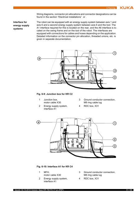
6 PlanningWiring diagrams, connector pin allocations and connector designations can befound in the section “Electrical installations” or .Interface forenergy supplysystemsThe robot can be equipped with an energy supply system between axis 1 andaxis 6 and a second energy supply system between axis 6 and the tool. TheA1 interface required for this is located on the rear, and the A6 interface is locatedon the swing frame and on the tool of the robot. The interfaces areequipped with connections for cables and hoses depending on the application.Detailed information on the connector pin allocation, threaded unions, etc. isgiven in separate documentation.Fig. 6-9: Junction box for <strong>KR</strong> C21 Junction box,motor cable X302 Energy supply system,interface A13 Ground conductor connection,M8 ring cable lug4 RDC box, X31Fig. 6-10: Interface A1 for <strong>KR</strong> C41 MFH,motor cable X302 Energy supply system,interface A13 Ground conductor connection,M8 ring cable lug4 RDC box, X31Issued: 02.10.2012 Version: Spez <strong>KR</strong> <strong>700</strong> <strong>PA</strong> V7 en (PDF)51 / 69