Tab 36
Tab 36
Tab 36

You also want an ePaper? Increase the reach of your titles
YUMPU automatically turns print PDFs into web optimized ePapers that Google loves.
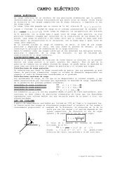
Adjustable Frequency DrivesSVX9000 Drives<strong>36</strong>.3Product Selection GuideController SelectionThe basic requirement ofcontroller selection is tomatch the output current,voltage and frequencycapabilities of the controllerwith the requirements of theconnected motor.Output CurrentThe controller must beselected and applied suchthat the average operatingmotor current andhorsepower do not exceedthe continuous current andhorsepower ratings of thecontroller. The intermittentoperating current must notexceed the intermittentcurrent rating of thecontroller.Motor ProtectionEaton adjustable frequencydrives include electronicmotor overload protectioncircuits that are designed tomeet the requirements ofNEC article 430-2 providedthat only one motor isconnected to the output ofthe controller.Output Voltage and FrequencyWhen they are shipped, AFcontrollers are adjusted toprovide a maximum outputvoltage and frequencyequivalent to the input linevoltage and frequency. Thecontrollers can be adjusted tooperate above line frequency,but a hazard of personal injuryor equipment damage mayexist when the motor isoperated above base speed.Before adjusting the drive tooperate above line frequency,make sure that the motor andthe driven machinery cansafely be operated at theresulting speed.FeaturesController FeaturesOperator Control and InterfaceRequirementsSince there are manypossible configurations andmany ways of achieving aspecific end result, it pays toconsider the operator controland interface requirementscarefully. A simplified andmore economical drivepackage can often beachieved by selecting fromstandard product offeringsrather than specifying acustom designedconfiguration.Installation CompatibilityThe successful applicationof an AC drive requires theassurance that the drive willbe compatible with theenvironment in which it willbe installed. In planning theinstallation, be sure tocarefully consider the heatproduced by the drive, thealtitude and temperaturelimits and the need for cleancooling air. Other importantconsiderations includeacoustical noise, vibration,electromagnetic compatibility,power quality, controller inputharmonic current and powerdistribution equipmentrequirements.Auxiliary Equipment andAccessoriesAdjustable drives aregenerally designed to have amotor directly connected tothe controller outputterminals with no otherequipment connected inseries or parallel. Motorstarters, disconnectswitches, surge absorbers,DV/DT suppression circuits,output chokes, outputtransformers and any otherequipment underconsideration for installationon the output of the controllershould not be installedwithout first requestingApplication Engineeringassistance. Power factorcorrection capacitors mustnever, under anycircumstances, be connectedat the output of the controller.They would serve no usefulpurpose, and they maydamage the controller.Enclosure Definitions●NEMA Type 1/IP21—Enclosures are intended forindoor use primarily toprovide a degree ofprotection against contactwith enclosed equipmentand provide a degree ofprotection against a limitedamount of falling dirt inlocations where unusualservice conditions do notexist. Top or side openingsin the NEMA Type 1/IP21enclosure allow for the freeexchange of inside andoutside air while meetingthe UL rod entry and rustresistance design tests.● NEMA Type 12/IP54—Enclosures are intendedfor indoor use primarily toprovide a degree ofprotection againstcirculating dust, falling dirtand dripping noncorrosiveliquids. To meet UL drip,dust and rust resistancetests, NEMA Type 12/IP54enclosures have noopenings to allow for theexchange of inside andoutside air.● Chassis IP00—Similar toProtected Chassis IP20except power terminals areprotected by plasticshielding only. Primarilyintended to be mountedinside a surroundingprotective enclosure.● NEMA Type 3R—Similar indesign to NEMA Type 12/IP54 except with morestringent design and testrequirements.<strong>36</strong><strong>36</strong><strong>36</strong><strong>36</strong><strong>36</strong><strong>36</strong><strong>36</strong><strong>36</strong><strong>36</strong><strong>36</strong><strong>36</strong><strong>36</strong><strong>36</strong><strong>36</strong><strong>36</strong><strong>36</strong><strong>36</strong><strong>36</strong><strong>36</strong><strong>36</strong><strong>36</strong><strong>36</strong><strong>36</strong><strong>36</strong><strong>36</strong><strong>36</strong><strong>36</strong><strong>36</strong><strong>36</strong><strong>36</strong>Volume 6—Solid-State Motor Control CA08100007E—April 2011 www.eaton.comV6-T<strong>36</strong>-15