Tab 36
Tab 36
Tab 36
You also want an ePaper? Increase the reach of your titles
YUMPU automatically turns print PDFs into web optimized ePapers that Google loves.
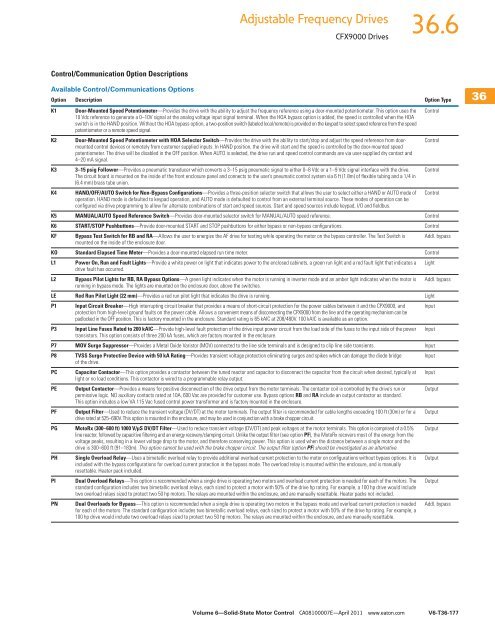
Adjustable Frequency DrivesCFX9000 Drives<strong>36</strong>.6Control/Communication Option DescriptionsAvailable Control/Communications OptionsOption Description Option TypeK1 Door-Mounted Speed Potentiometer—Provides the drive with the ability to adjust the frequency reference using a door-mounted potentiometer. This option uses the Control10 Vdc reference to generate a 0–10V signal at the analog voltage input signal terminal. When the HOA bypass option is added, the speed is controlled when the HOAswitch is in the HAND position. Without the HOA bypass option, a two-position switch (labeled local/remote) is provided on the keypad to select speed reference from the speedpotentiometer or a remote speed signal.K2 Door-Mounted Speed Potentiometer with HOA Selector Switch—Provides the drive with the ability to start/stop and adjust the speed reference from doormountedControlcontrol devices or remotely from customer supplied inputs. In HAND position, the drive will start and the speed is controlled by the door-mounted speedpotentiometer. The drive will be disabled in the OFF position. When AUTO is selected, the drive run and speed control commands are via user-supplied dry contact and4–20 mA signal.K3 3–15 psig Follower—Provides a pneumatic transducer which converts a 3–15 psig pneumatic signal to either 0–8 Vdc or a 1–9 Vdc signal interface with the drive. ControlThe circuit board is mounted on the inside of the front enclosure panel and connects to the user’s pneumatic control system via 6 ft (1.8m) of flexible tubing and a 1/4 in(6.4 mm) brass tube union.K4 HAND/OFF/AUTO Switch for Non-Bypass Configurations—Provides a three-position selector switch that allows the user to select either a HAND or AUTO mode of Controloperation. HAND mode is defaulted to keypad operation, and AUTO mode is defaulted to control from an external terminal source. These modes of operation can beconfigured via drive programming to allow for alternate combinations of start and speed sources. Start and speed sources include keypad, I/O and fieldbus.K5 MANUAL/AUTO Speed Reference Switch—Provides door-mounted selector switch for MANUAL/AUTO speed reference. ControlK6 START/STOP Pushbuttons—Provide door-mounted START and STOP pushbuttons for either bypass or non-bypass configurations. ControlKF Bypass Test Switch for RB and RA—Allows the user to energize the AF drive for testing while operating the motor on the bypass controller. The Test Switch is Addl. bypassmounted on the inside of the enclosure door.KO Standard Elapsed Time Meter—Provides a door-mounted elapsed run time meter. ControlL1 Power On, Run and Fault Lights—Provide a white power on light that indicates power to the enclosed cabinets, a green run light and a red fault light that indicates a Lightdrive fault has occurred.L2 Bypass Pilot Lights for RB, RA Bypass Options—A green light indicates when the motor is running in inverter mode and an amber light indicates when the motor is Addl. bypassrunning in bypass mode. The lights are mounted on the enclosure door, above the switches.LE Red Run Pilot Light (22 mm)—Provides a red run pilot light that indicates the drive is running. LightP1 Input Circuit Breaker—High interrupting circuit breaker that provides a means of short-circuit protection for the power cables between it and the CPX9000, and Inputprotection from high-level ground faults on the power cable. Allows a convenient means of disconnecting the CPX9000 from the line and the operating mechanism can bepadlocked in the OFF position. This is factory mounted in the enclosure. Standard rating is 65 kAIC at 208/480V. 100 kAIC is available as an option.P3 Input Line Fuses Rated to 200 kAIC—Provide high-level fault protection of the drive input power circuit from the load side of the fuses to the input side of the power Inputtransistors. This option consists of three 200 kA fuses, which are factory mounted in the enclosure.P7 MOV Surge Suppressor—Provides a Metal Oxide Varistor (MOV) connected to the line side terminals and is designed to clip line side transients. InputP8 TVSS Surge Protective Device with 50 kA Rating—Provides transient voltage protection eliminating surges and spikes which can damage the diode bridge Inputof the drive.PC Capacitor Contactor—This option provides a contactor between the tuned reactor and capacitor to disconnect the capacitor from the circuit when desired, typically at Inputlight or no load conditions. This contactor is wired to a programmable relay output.PE Output Contactor—Provides a means for positive disconnection of the drive output from the motor terminals. The contactor coil is controlled by the drive’s run or Outputpermissive logic. NO auxiliary contacts rated at 10A, 600 Vac are provided for customer use. Bypass options RB and RA include an output contactor as standard.This option includes a low VA 115 Vac fused control power transformer and is factory mounted in the enclosure.PF Output Filter—Used to reduce the transient voltage (DV/DT) at the motor terminals. The output filter is recommended for cable lengths exceeding 100 ft (30m) or for a Outputdrive rated at 525–690V. This option is mounted in the enclosure, and may be used in conjunction with a brake chopper circuit.PG MotoRx (300–600 ft) 1000 V/μS DV/DT Filter—Used to reduce transient voltage (DV/DT) and peak voltages at the motor terminals. This option is comprised of a 0.5% Outputline reactor, followed by capacitive filtering and an energy recovery/clamping circuit. Unlike the output filter (see option PF), the MotoRx recovers most of the energy from thevoltage peaks, resulting in a lower voltage drop to the motor, and therefore conserving power. This option is used when the distance between a single motor and thedrive is 300–600 ft (91–183m). This option cannot be used with the brake chopper circuit. The output filter (option PF) should be investigated as an alternative.PH Single Overload Relay—Uses a bimetallic overload relay to provide additional overload current protection to the motor on configurations without bypass options. It is Outputincluded with the bypass configurations for overload current protection in the bypass mode. The overload relay is mounted within the enclosure, and is manuallyresettable. Heater pack included.PI Dual Overload Relays—This option is recommended when a single drive is operating two motors and overload current protection is needed for each of the motors. The Outputstandard configuration includes two bimetallic overload relays, each sized to protect a motor with 50% of the drive hp rating. For example, a 100 hp drive would includetwo overload relays sized to protect two 50 hp motors. The relays are mounted within the enclosure, and are manually resettable. Heater packs not included.PN Dual Overloads for Bypass—This option is recommended when a single drive is operating two motors in the bypass mode and overload current protection is neededfor each of the motors. The standard configuration includes two bimetallic overload relays, each sized to protect a motor with 50% of the drive hp rating. For example, a100 hp drive would include two overload relays sized to protect two 50 hp motors. The relays are mounted within the enclosure, and are manually resettable.Addl. bypass<strong>36</strong><strong>36</strong><strong>36</strong><strong>36</strong><strong>36</strong><strong>36</strong><strong>36</strong><strong>36</strong><strong>36</strong><strong>36</strong><strong>36</strong><strong>36</strong><strong>36</strong><strong>36</strong><strong>36</strong><strong>36</strong><strong>36</strong><strong>36</strong><strong>36</strong><strong>36</strong><strong>36</strong><strong>36</strong><strong>36</strong><strong>36</strong><strong>36</strong><strong>36</strong><strong>36</strong><strong>36</strong><strong>36</strong><strong>36</strong>Volume 6—Solid-State Motor Control CA08100007E—April 2011 www.eaton.comV6-T<strong>36</strong>-177


