Tab 36
Tab 36
Tab 36
Create successful ePaper yourself
Turn your PDF publications into a flip-book with our unique Google optimized e-Paper software.
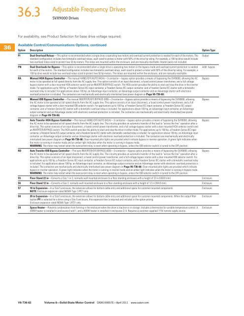
<strong>36</strong>.3Adjustable Frequency DrivesSVX9000 Drives<strong>36</strong><strong>36</strong><strong>36</strong><strong>36</strong><strong>36</strong><strong>36</strong><strong>36</strong><strong>36</strong><strong>36</strong><strong>36</strong><strong>36</strong><strong>36</strong><strong>36</strong><strong>36</strong><strong>36</strong><strong>36</strong><strong>36</strong><strong>36</strong><strong>36</strong><strong>36</strong><strong>36</strong><strong>36</strong><strong>36</strong><strong>36</strong><strong>36</strong><strong>36</strong><strong>36</strong><strong>36</strong><strong>36</strong><strong>36</strong>For availability, see Product Selection for base drive voltage required.Available Control/Communications Options, continuedOption Description Option TypePI Dual Overload Relays—This option is recommended when a single drive is operating two motors and overload current protection is needed for each of the motors. The Outputstandard configuration includes two bimetallic overload relays, each sized to protect a motor with 50% of the drive hp rating. For example, a 100 hp drive would includetwo overload relays sized to protect two 50 hp motors. The relays are mounted within the enclosure, and are manually resettable. Heater packs not included.PN Dual Overloads for Bypass—This option is recommended when a single drive is operating two motors in the bypass mode and overload current protection is needed Addl. bypassfor each of the motors. The standard configuration includes two bimetallic overload relays, each sized to protect a motor with 50% of the drive hp rating. For example, a100 hp drive would include two overload relays sized to protect two 50 hp motors. The relays are mounted within the enclosure, and are manually resettable.RA Manual HOA Bypass Controller—The manual HAND/OFF/AUTO (HOA)—3-contactor—bypass option provides a means of bypassing the SVX9000, allowing the AC Bypassmotor to be operated at full speed directly from the AC supply line. This option consists of an input disconnect, a fused control power transformer, and a full voltagebypass starter with a door mounted HOA selector switch and an INVERTER/BYPASS switch. The HOA switch provides the ability to start and stop the drive in the invertermode. For applications up to 100 hp, a Freedom Series IEC input contactor, a Freedom Series IEC output contactor, and a Freedom Series IEC starter with a bimetallicoverload relay is included. For applications above 100 hp, an Advantage input contactor, an Advantage output contactor and an Advantage starter with electronicoverload protection is included. The contactors are mechanically and electrically interlocked (see power diagram on Page V6-T<strong>36</strong>-66).RB Manual IOB Bypass Controller—The manual INVERTER/OFF/BYPASS (IOB)—3-contactor—bypass option provides a means of bypassing the SVX9000, allowing Bypassthe AC motor to be operated at full speed directly from the AC supply line. This option consists of an input disconnect, a fused control power transformer, and a fullvoltage bypass starter with a door mounted IOB selector switch. For applications up to 100 hp, a Freedom Series IEC input contactor, a Freedom Series IEC outputcontactor, and a Freedom Series IEC starter with a bimetallic overload relay is included. For applications above 100 hp, an Advantage input contactor, an Advantageoutput contactor and an Advantage starter with electronic overload protection is included. The contactors are mechanically and electrically interlocked (see powerdiagram on Page V6-T<strong>36</strong>-66).RC Auto Transfer HOA Bypass Controller—The manual HAND/OFF/AUTO (HOA)—3-contactor—bypass option provides a means of bypassing the SVX9000, allowing Bypassthe AC motor to be operated at full speed directly from the AC supply line. The circuitry provides an automatic transfer of the load to “across the line” operation after adrive trip. This option consists of an input disconnect, a fused control power transformer, and a full voltage bypass starter with a door mounted HOA selector switch andan INVERTER/BYPASS switch. The HOA switch provides the ability to start and stop the drive in either mode. For applications up to 100 hp, a Freedom Series IEC inputcontactor, a Freedom Series IEC output contactor, and a Freedom Series IEC starter with a bimetallic overload relay is included. For applications above 100 hp, an Advantage inputcontactor, an Advantage output contactor and an Advantage starter with electronic overload protection is included. The contactors are mechanically and electricallyinterlocked (see power diagram on Page V6-T<strong>36</strong>-66). Door-mounted pilot lights are provided which indicate bypass or inverter operation. A green light indicates whenthe motor is running in inverter mode and an amber light indicates when the motor is running in bypass mode.WARNING: The motor may restart when the overcurrent relay is reset when operating in bypass, unless the IOB selector switch is turned to the OFF position.RD Auto Transfer IOB Bypass Controller—The auto INVERTER/OFF/BYPASS (IOB)—3-contactor—bypass option provides a means of bypassing the SVX9000, allowing Bypassthe AC motor to be operated at full speed directly from the AC supply line. The circuitry provides an automatic transfer of the load to “across the line” operation after adrive trip. This option consists of an input disconnect, a fused control power transformer, and a full voltage bypass starter with a door mounted IOB selector switch. Forapplications up to 100 hp, a Freedom Series IEC input contactor, a Freedom Series IEC output contactor, and a Freedom Series IEC starter with a bimetallic overload relayis included. For applications above 100 hp, an Advantage input contactor, an Advantage output contactor and an Advantage starter with electronic overload protection isincluded. The contactors are mechanically and electrically interlocked (see power diagram on Page V6-T<strong>36</strong>-66). Door-mounted pilot lights are provided which indicatebypass or inverter operation. A green light indicates when the motor is running in inverter mode and an amber light indicates when the motor is running in bypass mode.WARNING: The motor may restart when the overcurrent relay is reset when operating in bypass, unless the IOB selector switch is turned to the OFF position.S5 Floor Stand 22 in—Converts a Size 1 or 2, normally wall mounted enclosure to a floor standing enclosure with a height of 22 in (558.8 mm). EnclosureS6 Floor Stand 12 in—Converts a Size 2, normally wall mounted enclosure to a floor standing enclosure with a height of 12 in (304.8 mm). EnclosureS7 10 in Expansion—In a Size 5 enclosure, the extension allows for bottom cable entry and additional space for customer mounted components.EnclosureNOTE: Enclosure expansion rated NEMA Type 1/IP21 only.S8 20 in Expansion—In a Size 5 enclosure, the extension allows for bottom cable entry and additional space for customer mounted components. When the output filter Enclosure(option PF) is selected for a drive using a Size 5 enclosure, this expansion box is required and included in the option pricing.Enclosure expansion rated NEMA Type 1/IP21 only.S9 Space Heater—Prevents condensation from forming in the enclosure when the drive is inactive or in storage. Includes a thermostat for variable temperature control. A200W heater is installed in enclosures 0 and 1, and a 400W heater is installed in enclosures 2–5. Requires a customer supplied 115V remote supply source.EnclosureV6-T<strong>36</strong>-62Volume 6—Solid-State Motor Control CA08100007E—April 2011 www.eaton.com


