

Fatigue Crack Growth in 7050T7451 Aluminium Alloy Thick Section ...
Fatigue Crack Growth in 7050T7451 Aluminium Alloy Thick Section ...
Fatigue Crack Growth in 7050T7451 Aluminium Alloy Thick Section ...

You also want an ePaper? Increase the reach of your titles
YUMPU automatically turns print PDFs into web optimized ePapers that Google loves.
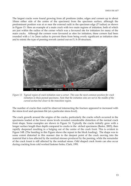
DSTO-TR-1477The largest cracks were found grow<strong>in</strong>g from all positions (sides, edges and corners up to about10mm either side of the centre of the specimen) from the specimen surface, although thepredom<strong>in</strong>ant position was at or near the external radii <strong>in</strong> the specimen edge (5”radius) as shown<strong>in</strong> Figure 13. Here an example of a ma<strong>in</strong> crack with two ma<strong>in</strong> regions of <strong>in</strong>itiation, both of whichare just with<strong>in</strong> the radius of the corner which was a favoured site for <strong>in</strong>itiation for many of thema<strong>in</strong> cracks. Although the corners were favoured as sites for <strong>in</strong>itiation, these corners had beenrounded with a 1 to 2mm radius to prevent them from be<strong>in</strong>g overly significant as <strong>in</strong>itiation sitesand to mimic the type of peen<strong>in</strong>g rework carried out on F/A-18 structure.Figure 13 Typical region of crack <strong>in</strong>itiation near a corner. This was the most common position for crack<strong>in</strong>itiation <strong>in</strong> these peened specimens. Note that the <strong>in</strong>itiation sites are not <strong>in</strong> the middle of thecurved section but closer to the transition region.The number of cracks that could be observed <strong>in</strong>tersect<strong>in</strong>g the fracture appeared to <strong>in</strong>creased withthe stress level and specimen life (at a particular stress level).The crack growth around the orig<strong>in</strong>s of the cracks, particularly the cracks which occurred <strong>in</strong> thespecimens loaded at the lower stress levels revealed considerable distortion of the normal crackfront shape. Some examples are shown <strong>in</strong> Figure 14. Typically the cracks <strong>in</strong>itially grew with alonger surface length than depth compared to cracks <strong>in</strong> the etched specimens (Barter, 2003), thenrapidly deepened result<strong>in</strong>g <strong>in</strong> a bulg<strong>in</strong>g out of the centre of the crack front. This is evident <strong>in</strong>Figure 14B. (The band<strong>in</strong>g <strong>in</strong> this Figure shows the repeat <strong>in</strong> the block load<strong>in</strong>g). The shape was tosome extent distorted <strong>in</strong> this manner due to the deepest po<strong>in</strong>t of the crack mov<strong>in</strong>g <strong>in</strong>to thematerial that is less affected by the residual stresses produced by the peen<strong>in</strong>g, while the rema<strong>in</strong>derof the crack fount is still affected by the residual stress. Odd shaped crack fronts can also occurdur<strong>in</strong>g crack<strong>in</strong>g from cold worked fastener holes, Clark, 1991.13


