Bursting and Spalling in Pretensioned U-Beams - Ferguson ...
Bursting and Spalling in Pretensioned U-Beams - Ferguson ...
Bursting and Spalling in Pretensioned U-Beams - Ferguson ...
Create successful ePaper yourself
Turn your PDF publications into a flip-book with our unique Google optimized e-Paper software.
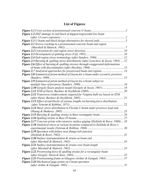
List of FiguresFigure 1.1 Cross section of pretensioned concrete U-beam .............................................. 2Figure 1.2 DEF damage <strong>in</strong> end block of dapped trapezoidal box beam(after 13 years exposure) ........................................................................................ 2Figure 1.3 U-beam end-block design alternatives for skewed ends ................................... 3Figure 2.1 Severe crack<strong>in</strong>g <strong>in</strong> a pretensioned concrete beam end region(Marshall & Mattock, 1962) .................................................................................. 7Figure 2.2 Convention for end-region stress direction .................................................... 10Figure 2.3 Development of splitt<strong>in</strong>g stress (Uijl, 1991) ................................................... 10Figure 2.4 End-region stress term<strong>in</strong>ology (after S<strong>and</strong>ers, 1990) .................................... 12Figure 2.5 <strong>Burst<strong>in</strong>g</strong> & spall<strong>in</strong>g stress distributions (after Lenschow & Sozen, 1965) .... 12Figure 2.6 Effect of burst<strong>in</strong>g & spall<strong>in</strong>g stresses through exaggerated deformationsof beam with discont<strong>in</strong>uities (after Hawk<strong>in</strong>s, 1966) ............................................. 13Figure 2.7 Analytical approaches for prestressed beam end regions .............................. 14Figure 2.8 Symmetrical prism method of Guyon for a beam under eccentric prestress(S<strong>and</strong>ers, 1990) ..................................................................................................... 15Figure 2.9 Symmetrical prism method of Guyon for a beam subject tomultiple l<strong>in</strong>es of prestress (S<strong>and</strong>ers, 1990) ........................................................... 16Figure 2.10 Gergely-Sozen analysis model (Gergely & Sozen, 1967) ............................. 18Figure 2.11 STM of Davis, Buckner & Ozyildirim (2005) ............................................... 20Figure 2.12 Transverse re<strong>in</strong>forcement required for Virg<strong>in</strong>ia bulb tee based on STM(after Davis, Buckner & Ozyildirim, 2005) .......................................................... 21Figure 2.13 Effect of end blocks of various lengths on burst<strong>in</strong>g force distribution(after Yettram & Robb<strong>in</strong>s, 1971) ......................................................................... 22Figure 2.14 Shear stress distribution <strong>in</strong> Florida U-beam under prestress load only(Huang & Shahawy, 2005) ................................................................................... 23Figure 2.15 <strong>Burst<strong>in</strong>g</strong> & spall<strong>in</strong>g stra<strong>in</strong>s <strong>in</strong> Base rectangular beam ................................ 26Figure 2.16 <strong>Spall<strong>in</strong>g</strong> stra<strong>in</strong>s <strong>in</strong> Base IT-beams ................................................................ 27Figure 2.17 Concrete prism with extensive surface gag<strong>in</strong>g (Zieliński & Rowe, 1960).... 28Figure 2.18 Analytical stress at various locations compared to Zieliński & Rowe’sexperimental results (Yettram & Robb<strong>in</strong>s, 1969) ................................................. 30Figure 2.19 Specimen with failure near flange/web junction(Zieliński & Rowe, 1962) ...................................................................................... 31Figure 2.20 Surface <strong>in</strong>strumentation & stra<strong>in</strong>s at beam end(after Marshall & Mattock, 1962) ........................................................................ 33Figure 2.21 Surface <strong>in</strong>strumentation & stra<strong>in</strong>s over beam length(after Marshall & Mattock, 1962) ........................................................................ 33Figure 2.22 Prestress<strong>in</strong>g force & spall<strong>in</strong>g stra<strong>in</strong>s for a rectangular beam(after Gergely, Sozen & Siess, 1963) .................................................................... 35Figure 2.23 Pretension<strong>in</strong>g frame at Glasgow (Arthur & Ganguli, 1965) ....................... 37Figure 2.24 Mechanical gage po<strong>in</strong>ts on I-beam specimen(after Arthur & Ganguli, 1965) ............................................................................ 37xii


