Bursting and Spalling in Pretensioned U-Beams - Ferguson ...
Bursting and Spalling in Pretensioned U-Beams - Ferguson ...
Bursting and Spalling in Pretensioned U-Beams - Ferguson ...

Create successful ePaper yourself
Turn your PDF publications into a flip-book with our unique Google optimized e-Paper software.
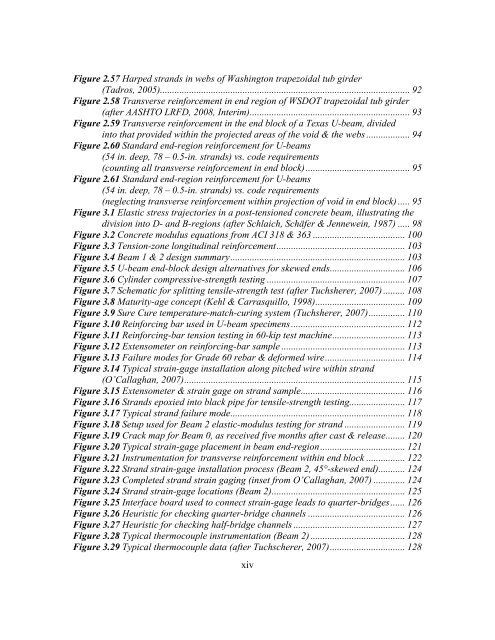
Figure 2.57 Harped str<strong>and</strong>s <strong>in</strong> webs of Wash<strong>in</strong>gton trapezoidal tub girder(Tadros, 2005)....................................................................................................... 92Figure 2.58 Transverse re<strong>in</strong>forcement <strong>in</strong> end region of WSDOT trapezoidal tub girder(after AASHTO LRFD, 2008, Interim) .................................................................. 93Figure 2.59 Transverse re<strong>in</strong>forcement <strong>in</strong> the end block of a Texas U-beam, divided<strong>in</strong>to that provided with<strong>in</strong> the projected areas of the void & the webs .................. 94Figure 2.60 St<strong>and</strong>ard end-region re<strong>in</strong>forcement for U-beams(54 <strong>in</strong>. deep, 78 – 0.5-<strong>in</strong>. str<strong>and</strong>s) vs. code requirements(count<strong>in</strong>g all transverse re<strong>in</strong>forcement <strong>in</strong> end block) ........................................... 95Figure 2.61 St<strong>and</strong>ard end-region re<strong>in</strong>forcement for U-beams(54 <strong>in</strong>. deep, 78 – 0.5-<strong>in</strong>. str<strong>and</strong>s) vs. code requirements(neglect<strong>in</strong>g transverse re<strong>in</strong>forcement with<strong>in</strong> projection of void <strong>in</strong> end block) ..... 95Figure 3.1 Elastic stress trajectories <strong>in</strong> a post-tensioned concrete beam, illustrat<strong>in</strong>g thedivision <strong>in</strong>to D- <strong>and</strong> B-regions (after Schlaich, Schäfer & Jennewe<strong>in</strong>, 1987) ..... 98Figure 3.2 Concrete modulus equations from ACI 318 & 363 ...................................... 100Figure 3.3 Tension-zone longitud<strong>in</strong>al re<strong>in</strong>forcement ..................................................... 103Figure 3.4 Beam 1 & 2 design summary ........................................................................ 103Figure 3.5 U-beam end-block design alternatives for skewed ends ............................... 106Figure 3.6 Cyl<strong>in</strong>der compressive-strength test<strong>in</strong>g ......................................................... 107Figure 3.7 Schematic for splitt<strong>in</strong>g tensile-strength test (after Tuchsherer, 2007) ......... 108Figure 3.8 Maturity-age concept (Kehl & Carrasquillo, 1998) ..................................... 109Figure 3.9 Sure Cure temperature-match-cur<strong>in</strong>g system (Tuchsherer, 2007) ............... 110Figure 3.10 Re<strong>in</strong>forc<strong>in</strong>g bar used <strong>in</strong> U-beam specimens ............................................... 112Figure 3.11 Re<strong>in</strong>forc<strong>in</strong>g-bar tension test<strong>in</strong>g <strong>in</strong> 60-kip test mach<strong>in</strong>e .............................. 113Figure 3.12 Extensometer on re<strong>in</strong>forc<strong>in</strong>g-bar sample ................................................... 113Figure 3.13 Failure modes for Grade 60 rebar & deformed wire ................................. 114Figure 3.14 Typical stra<strong>in</strong>-gage <strong>in</strong>stallation along pitched wire with<strong>in</strong> str<strong>and</strong>(O’Callaghan, 2007) ........................................................................................... 115Figure 3.15 Extensometer & stra<strong>in</strong> gage on str<strong>and</strong> sample ........................................... 116Figure 3.16 Str<strong>and</strong>s epoxied <strong>in</strong>to black pipe for tensile-strength test<strong>in</strong>g....................... 117Figure 3.17 Typical str<strong>and</strong> failure mode ........................................................................ 118Figure 3.18 Setup used for Beam 2 elastic-modulus test<strong>in</strong>g for str<strong>and</strong> ......................... 119Figure 3.19 Crack map for Beam 0, as received five months after cast & release ........ 120Figure 3.20 Typical stra<strong>in</strong>-gage placement <strong>in</strong> beam end-region ................................... 121Figure 3.21 Instrumentation for transverse re<strong>in</strong>forcement with<strong>in</strong> end block ................ 122Figure 3.22 Str<strong>and</strong> stra<strong>in</strong>-gage <strong>in</strong>stallation process (Beam 2, 45°-skewed end) ........... 124Figure 3.23 Completed str<strong>and</strong> stra<strong>in</strong> gag<strong>in</strong>g (<strong>in</strong>set from O’Callaghan, 2007) ............. 124Figure 3.24 Str<strong>and</strong> stra<strong>in</strong>-gage locations (Beam 2) ....................................................... 125Figure 3.25 Interface board used to connect stra<strong>in</strong>-gage leads to quarter-bridges ...... 126Figure 3.26 Heuristic for check<strong>in</strong>g quarter-bridge channels ........................................ 126Figure 3.27 Heuristic for check<strong>in</strong>g half-bridge channels .............................................. 127Figure 3.28 Typical thermocouple <strong>in</strong>strumentation (Beam 2) ....................................... 128Figure 3.29 Typical thermocouple data (after Tuchscherer, 2007) ............................... 128xiv