- Page 4:
Signaling inTelecommunicationNetwor
- Page 7 and 8:
Copyright # 2007 by John Wiley & So
- Page 10 and 11:
CONTENTSPreface to the Second Editi
- Page 12 and 13:
CONTENTSix8.4 Basic Error Correctio
- Page 14 and 15:
CONTENTSxiChapter 16 Transaction Ca
- Page 16 and 17:
PREFACE TO THESECOND EDITIONThe fir
- Page 18 and 19:
1INTRODUCTION TOTELECOMMUNICATIONST
- Page 20 and 21:
1.1 TELECOMMUNICATION NETWORKS 3Fig
- Page 22 and 23:
1.1 TELECOMMUNICATION NETWORKS 5Fig
- Page 24 and 25:
1.1 TELECOMMUNICATION NETWORKS 7Fig
- Page 26 and 27:
1.2 NUMBERING PLANS 9Local exchange
- Page 28 and 29:
1.2 NUMBERING PLANS 11The NANP (for
- Page 30 and 31:
1.3 DIGIT ANALYSIS AND ROUTING 13Fi
- Page 32 and 33:
1.3 DIGIT ANALYSIS AND ROUTING 15Fi
- Page 34 and 35:
1.4 ANALOG TRANSMISSION 17In the IC
- Page 36 and 37:
1.4 ANALOG TRANSMISSION 19Figure 1.
- Page 38 and 39:
1.4 ANALOG TRANSMISSION 21Figure 1.
- Page 40 and 41:
1.5 DIGITAL TRANSMISSION 23land bas
- Page 42 and 43:
1.5 DIGITAL TRANSMISSION 25Figure 1
- Page 44 and 45:
1.5 DIGITAL TRANSMISSION 27Figure 1
- Page 46 and 47:
1.6 SPECIAL TRANSMISSION EQUIPMENT
- Page 48 and 49:
1.6 SPECIAL TRANSMISSION EQUIPMENT
- Page 50 and 51:
1.6 SPECIAL TRANSMISSION EQUIPMENT
- Page 52 and 53:
1.7 EXCHANGES 35Figure 1.7-2. Local
- Page 54 and 55:
1.7 EXCHANGES 37Figure 1.7-4. Excha
- Page 56 and 57:
1.8 ACCESS NETWORKS AND LINE CONCEN
- Page 58 and 59:
1.10 REFERENCES 41ISDNITUITU-TLATAL
- Page 60 and 61:
2INTRODUCTION TO SIGNALING2.1 OVERV
- Page 62 and 63:
2.1 OVERVIEW 45networks and in the
- Page 64 and 65:
2.1 OVERVIEW 47not involved in a ca
- Page 66 and 67:
2.2 STANDARDS FOR SIGNALING SYSTEMS
- Page 68 and 69:
2.3 ACRONYMS 51. Communications Sta
- Page 70:
2.4 REFERENCES 537. R. B. Robrock,
- Page 73 and 74:
56 SUBSCRIBER SIGNALINGFigure 3.1-1
- Page 75 and 76:
58 SUBSCRIBER SIGNALINGFigure 3.2-1
- Page 77 and 78:
60 SUBSCRIBER SIGNALING3.2.5 Tones
- Page 79 and 80:
62 SUBSCRIBER SIGNALINGHook Status.
- Page 81 and 82:
64 SUBSCRIBER SIGNALINGthe low-grou
- Page 83 and 84:
66 SUBSCRIBER SIGNALING3.4.3 Tones
- Page 85 and 86:
68 SUBSCRIBER SIGNALINGCall Waiting
- Page 87 and 88:
70 SUBSCRIBER SIGNALING3.6.1 Caller
- Page 89 and 90:
72 SUBSCRIBER SIGNALINGCalled Party
- Page 91 and 92:
74 SUBSCRIBER SIGNALINGRRRSSSCSITSL
- Page 93 and 94:
76 CHANNEL-ASSOCIATED INTEREXCHANGE
- Page 95 and 96:
78 CHANNEL-ASSOCIATED INTEREXCHANGE
- Page 97 and 98:
80 CHANNEL-ASSOCIATED INTEREXCHANGE
- Page 99 and 100:
82 CHANNEL-ASSOCIATED INTEREXCHANGE
- Page 101 and 102:
84 CHANNEL-ASSOCIATED INTEREXCHANGE
- Page 103 and 104:
86 CHANNEL-ASSOCIATED INTEREXCHANGE
- Page 105 and 106:
88 CHANNEL-ASSOCIATED INTEREXCHANGE
- Page 107 and 108:
90 CHANNEL-ASSOCIATED INTEREXCHANGE
- Page 109 and 110:
92 CHANNEL-ASSOCIATED INTEREXCHANGE
- Page 111 and 112:
94 CHANNEL-ASSOCIATED INTEREXCHANGE
- Page 113 and 114:
96 CHANNEL-ASSOCIATED INTEREXCHANGE
- Page 115 and 116:
98 CHANNEL-ASSOCIATED INTEREXCHANGE
- Page 117 and 118:
100 CHANNEL-ASSOCIATED INTEREXCHANG
- Page 119 and 120:
102 CHANNEL-ASSOCIATED INTEREXCHANG
- Page 121 and 122:
104 CHANNEL-ASSOCIATED INTEREXCHANG
- Page 123 and 124:
106 CHANNEL-ASSOCIATED INTEREXCHANG
- Page 125 and 126:
108 CHANNEL-ASSOCIATED INTEREXCHANG
- Page 128 and 129:
5INTRODUCTION TOCOMMON-CHANNEL SIGN
- Page 130 and 131:
5.1 SIGNALING NETWORKS 113Figure 5.
- Page 132 and 133:
5.1 SIGNALING NETWORKS 115Quasiasso
- Page 134 and 135:
5.1 SIGNALING NETWORKS 117Figure 5.
- Page 136 and 137:
5.2 SIGNALING LINKS AND SIGNAL UNIT
- Page 138 and 139:
5.2 SIGNALING LINKS AND SIGNAL UNIT
- Page 140 and 141:
5.2 SIGNALING LINKS AND SIGNAL UNIT
- Page 142 and 143:
5.3 ACRONYMS 125In the final step o
- Page 147 and 148:
130 SIGNALING IN ACCESS NETWORKSTim
- Page 149 and 150:
132 SIGNALING IN ACCESS NETWORKSCom
- Page 151 and 152:
134 SIGNALING IN ACCESS NETWORKSTAB
- Page 153 and 154:
136 SIGNALING IN ACCESS NETWORKSFig
- Page 155 and 156:
138 SIGNALING IN ACCESS NETWORKSFig
- Page 157 and 158:
140 SIGNALING IN ACCESS NETWORKSinf
- Page 159 and 160: 142 SIGNALING IN ACCESS NETWORKSinf
- Page 161 and 162: 144 SIGNALING IN ACCESS NETWORKSTAB
- Page 163 and 164: 146 SIGNALING IN ACCESS NETWORKSFig
- Page 165 and 166: 148 SIGNALING IN ACCESS NETWORKSC-C
- Page 167 and 168: 150 SIGNALING IN ACCESS NETWORKSTAB
- Page 169 and 170: 152 SIGNALING IN ACCESS NETWORKScan
- Page 171 and 172: 154 SIGNALING IN ACCESS NETWORKSIDT
- Page 174 and 175: 7INTRODUCTION TO SIGNALINGSYSTEM NO
- Page 176 and 177: 7.1 SS7 STRUCTURE 159Message Transf
- Page 178 and 179: 7.2 IDENTIFICATION OF SIGNALING POI
- Page 180 and 181: 7.3 SS7 SIGNAL UNITS AND PRIMITIVES
- Page 182 and 183: 7.4 ACRONYMS 165Figure 7.3-3 shows
- Page 184 and 185: 8SS7 MESSAGE TRANSFER PARTThe Messa
- Page 186 and 187: 8.2 MTP LEVEL 1 1698.1.2 Message Tr
- Page 188 and 189: 8.3 OVERVIEW OF MTP LEVEL 2 171In e
- Page 190 and 191: 8.3 OVERVIEW OF MTP LEVEL 2 173The
- Page 192 and 193: 8.4 BASIC ERROR CORRECTION 175Figur
- Page 194 and 195: 8.4 BASIC ERROR CORRECTION 177Figur
- Page 196 and 197: 8.5 PREVENTIVE CYCLIC RETRANSMISSIO
- Page 198 and 199: 8.6 SIGNALING LINK MANAGEMENT 181In
- Page 200 and 201: 8.7 OVERVIEW OF MTP LEVEL 3 183Figu
- Page 202 and 203: 8.8 MTP3 SIGNALING MESSAGE HANDLING
- Page 204 and 205: 8.8 MTP3 SIGNALING MESSAGE HANDLING
- Page 206 and 207: 8.8 MTP3 SIGNALING MESSAGE HANDLING
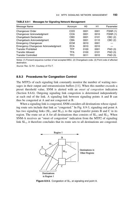
- Page 208 and 209: 8.9 MTP3 SIGNALING NETWORK MANAGEME
- Page 212 and 213: 8.9 MTP3 SIGNALING NETWORK MANAGEME
- Page 214 and 215: 8.9 MTP3 SIGNALING NETWORK MANAGEME
- Page 216 and 217: 8.10 ACRONYMS 199H1 Message heading
- Page 218 and 219: 9TELEPHONE USER PARTThe Telephone U
- Page 220 and 221: 9.2 CALL-CONTROL MESSAGES AND SIGNA
- Page 222 and 223: 9.2 CALL-CONTROL MESSAGES AND SIGNA
- Page 224 and 225: 9.2 CALL-CONTROL MESSAGES AND SIGNA
- Page 226 and 227: 9.2 CALL-CONTROL MESSAGES AND SIGNA
- Page 228 and 229: 9.3 BASIC SIGNALING SEQUENCES 211TA
- Page 230 and 231: 9.3 BASIC SIGNALING SEQUENCES 213Wh
- Page 232 and 233: 9.3 BASIC SIGNALING SEQUENCES 215On
- Page 234 and 235: 9.4 TUP SUPPORT OF ADDITIONAL SERVI
- Page 236 and 237: 9.4 TUP SUPPORT OF ADDITIONAL SERVI
- Page 238 and 239: 9.5 OTHER TUP PROCEDURES, MESSAGES,
- Page 240 and 241: 9.5 OTHER TUP PROCEDURES, MESSAGES,
- Page 242 and 243: 9.6 VERSIONS OF TUP SIGNALING 2259.
- Page 244 and 245: 9.7 ACRONYMS 227ACM Address Complet
- Page 246: 9.8 REFERENCES 229SAOSECSHPSISIFSIM
- Page 249 and 250: 232 DIGITAL SUBSCRIBER SIGNALING SY
- Page 251 and 252: 234 DIGITAL SUBSCRIBER SIGNALING SY
- Page 253 and 254: 236 DIGITAL SUBSCRIBER SIGNALING SY
- Page 255 and 256: 238 DIGITAL SUBSCRIBER SIGNALING SY
- Page 257 and 258: 240 DIGITAL SUBSCRIBER SIGNALING SY
- Page 259 and 260: 242 DIGITAL SUBSCRIBER SIGNALING SY
- Page 261 and 262:
244 DIGITAL SUBSCRIBER SIGNALING SY
- Page 263 and 264:
246 DIGITAL SUBSCRIBER SIGNALING SY
- Page 265 and 266:
248 DIGITAL SUBSCRIBER SIGNALING SY
- Page 267 and 268:
250 DIGITAL SUBSCRIBER SIGNALING SY
- Page 269 and 270:
TABLE 10.3-3 Information Elements i
- Page 271 and 272:
254 DIGITAL SUBSCRIBER SIGNALING SY
- Page 273 and 274:
256 DIGITAL SUBSCRIBER SIGNALING SY
- Page 275 and 276:
258 DIGITAL SUBSCRIBER SIGNALING SY
- Page 277 and 278:
260 DIGITAL SUBSCRIBER SIGNALING SY
- Page 279 and 280:
262 DIGITAL SUBSCRIBER SIGNALING SY
- Page 281 and 282:
264 DIGITAL SUBSCRIBER SIGNALING SY
- Page 283 and 284:
266 DIGITAL SUBSCRIBER SIGNALING SY
- Page 285 and 286:
268 DIGITAL SUBSCRIBER SIGNALING SY
- Page 287 and 288:
270 DIGITAL SUBSCRIBER SIGNALING SY
- Page 289 and 290:
272 DIGITAL SUBSCRIBER SIGNALING SY
- Page 291 and 292:
274 DIGITAL SUBSCRIBER SIGNALING SY
- Page 294 and 295:
11ISDN USER PARTThis chapter resume
- Page 296 and 297:
11.2 ISUP MESSAGES, FORMATS, AND PA
- Page 298 and 299:
11.2 ISUP MESSAGES, FORMATS, AND PA
- Page 300 and 301:
11.2 ISUP MESSAGES, FORMATS, AND PA
- Page 302 and 303:
TABLE 11.2-2 Parameters in ISUP Cal
- Page 304 and 305:
11.2 ISUP MESSAGES, FORMATS, AND PA
- Page 306 and 307:
11.2 ISUP MESSAGES, FORMATS, AND PA
- Page 308 and 309:
11.2 ISUP MESSAGES, FORMATS, AND PA
- Page 310 and 311:
11.2 ISUP MESSAGES, FORMATS, AND PA
- Page 312 and 313:
11.2 ISUP MESSAGES, FORMATS, AND PA
- Page 314 and 315:
11.3 SIGNALING FOR CALLS BETWEEN IS
- Page 316 and 317:
11.3 SIGNALING FOR CALLS BETWEEN IS
- Page 318 and 319:
11.4 CALLS INVOLVING ANALOG SUBSCRI
- Page 320 and 321:
11.4 CALLS INVOLVING ANALOG SUBSCRI
- Page 322 and 323:
11.5 END-TO-END SIGNALING 305In the
- Page 324 and 325:
11.5 END-TO-END SIGNALING 307Figure
- Page 326 and 327:
11.6 OTHER SIGNALING PROCEDURES 309
- Page 328 and 329:
11.6 OTHER SIGNALING PROCEDURES 311
- Page 330 and 331:
11.6 OTHER SIGNALING PROCEDURES 313
- Page 332 and 333:
11.6 OTHER SIGNALING PROCEDURES 315
- Page 334 and 335:
11.7 SIGNALING PROCEDURES FOR FAILE
- Page 336 and 337:
11.8 ISUP SIGNALING IN THE INTERNAT
- Page 338 and 339:
11.9 ISUP SIGNALING IN THE UNITED S
- Page 340 and 341:
11.10 ACRONYMS 323transferred trans
- Page 342 and 343:
11.11 REFERENCES 325SCCP Signaling
- Page 344 and 345:
12SIGNALING IN CELLULARMOBILE TELEC
- Page 346 and 347:
12.1 INTRODUCTION TO CELLULAR MOBIL
- Page 348 and 349:
12.1 INTRODUCTION TO CELLULAR MOBIL
- Page 350 and 351:
12.1 INTRODUCTION TO CELLULAR MOBIL
- Page 352 and 353:
12.1 INTRODUCTION TO CELLULAR MOBIL
- Page 354 and 355:
Figure 12.2-1. Transmission of mess
- Page 356 and 357:
12.3 INTRODUCTION TO AMPS SIGNALING
- Page 358 and 359:
12.3 INTRODUCTION TO AMPS SIGNALING
- Page 360 and 361:
12.4 AMPS MESSAGE FORMATS AND PARAM
- Page 362 and 363:
12.4 AMPS MESSAGE FORMATS AND PARAM
- Page 364 and 365:
12.4 AMPS MESSAGE FORMATS AND PARAM
- Page 366 and 367:
12.4 AMPS MESSAGE FORMATS AND PARAM
- Page 368 and 369:
12.4 AMPS MESSAGE FORMATS AND PARAM
- Page 370 and 371:
12.5 AMPS SIGNALING PROCEDURES 353s
- Page 372 and 373:
12.5 AMPS SIGNALING PROCEDURES 355p
- Page 374 and 375:
12.6 SIGNALING IN IS-54 CELLULAR SY
- Page 376 and 377:
12.6 SIGNALING IN IS-54 CELLULAR SY
- Page 378 and 379:
12.6 SIGNALING IN IS-54 CELLULAR SY
- Page 380 and 381:
12.6 SIGNALING IN IS-54 CELLULAR SY
- Page 382 and 383:
12.7 INTRODUCTION TO THE GSM CELLUL
- Page 384 and 385:
12.7 INTRODUCTION TO THE GSM CELLUL
- Page 386 and 387:
12.7 INTRODUCTION TO THE GSM CELLUL
- Page 388 and 389:
12.7 INTRODUCTION TO THE GSM CELLUL
- Page 390 and 391:
12.8 SIGNALING BETWEEN MOBILE AND N
- Page 392 and 393:
12.8 SIGNALING BETWEEN MOBILE AND N
- Page 394 and 395:
12.8 SIGNALING BETWEEN MOBILE AND N
- Page 396 and 397:
12.8 SIGNALING BETWEEN MOBILE AND N
- Page 398 and 399:
12.9 LAYER 3 MESSAGES ON THE Um INT
- Page 400 and 401:
12.9 LAYER 3 MESSAGES ON THE Um INT
- Page 402 and 403:
12.10 ACRONYMS 385FVCGAWGSMIMEIIMSI
- Page 404:
12.11 REFERENCES 3875. Public Land
- Page 407 and 408:
390 AIR INTERFACE SIGNALING IN CDMA
- Page 409 and 410:
392 AIR INTERFACE SIGNALING IN CDMA
- Page 411 and 412:
394 AIR INTERFACE SIGNALING IN CDMA
- Page 413 and 414:
396 AIR INTERFACE SIGNALING IN CDMA
- Page 415 and 416:
398 AIR INTERFACE SIGNALING IN CDMA
- Page 417 and 418:
400 AIR INTERFACE SIGNALING IN CDMA
- Page 419 and 420:
402 AIR INTERFACE SIGNALING IN CDMA
- Page 421 and 422:
404 AIR INTERFACE SIGNALING IN CDMA
- Page 423 and 424:
406 AIR INTERFACE SIGNALING IN CDMA
- Page 425 and 426:
408 AIR INTERFACE SIGNALING IN CDMA
- Page 427 and 428:
410 AIR INTERFACE SIGNALING IN CDMA
- Page 429 and 430:
412 AIR INTERFACE SIGNALING IN CDMA
- Page 431 and 432:
TABLE 13.3-1 Forward CDMA Physical
- Page 433 and 434:
416 AIR INTERFACE SIGNALING IN CDMA
- Page 435 and 436:
418 AIR INTERFACE SIGNALING IN CDMA
- Page 437 and 438:
420 AIR INTERFACE SIGNALING IN CDMA
- Page 439 and 440:
422 AIR INTERFACE SIGNALING IN CDMA
- Page 441 and 442:
424 AIR INTERFACE SIGNALING IN CDMA
- Page 443 and 444:
426 AIR INTERFACE SIGNALING IN CDMA
- Page 445 and 446:
428 AIR INTERFACE SIGNALING IN CDMA
- Page 447 and 448:
430 AIR INTERFACE SIGNALING IN CDMA
- Page 449 and 450:
432 AIR INTERFACE SIGNALING IN CDMA
- Page 451 and 452:
434 AIR INTERFACE SIGNALING IN CDMA
- Page 453 and 454:
436 AIR INTERFACE SIGNALING IN CDMA
- Page 455 and 456:
438 AIR INTERFACE SIGNALING IN CDMA
- Page 457 and 458:
440 AIR INTERFACE SIGNALING IN CDMA
- Page 459 and 460:
442 AIR INTERFACE SIGNALING IN CDMA
- Page 461 and 462:
444 AIR INTERFACE SIGNALING IN CDMA
- Page 463 and 464:
446 AIR INTERFACE SIGNALING IN CDMA
- Page 465 and 466:
448 AIR INTERFACE SIGNALING IN CDMA
- Page 467 and 468:
450 AIR INTERFACE SIGNALING IN CDMA
- Page 469 and 470:
452 AIR INTERFACE SIGNALING IN CDMA
- Page 471 and 472:
454 AIR INTERFACE SIGNALING IN CDMA
- Page 473 and 474:
456 AIR INTERFACE SIGNALING IN CDMA
- Page 476 and 477:
14INTRODUCTION TOTRANSACTIONSThe TU
- Page 478 and 479:
14.2 SS7 ARCHITECTURE FOR TRANSACTI
- Page 480:
CCIS Common-channel interoffice sig
- Page 483 and 484:
466 SIGNALING CONNECTION CONTROL PA
- Page 485 and 486:
468 SIGNALING CONNECTION CONTROL PA
- Page 487 and 488:
TABLE 15.2-2 Parameters in SCCP Mes
- Page 489 and 490:
472 SIGNALING CONNECTION CONTROL PA
- Page 491 and 492:
474 SIGNALING CONNECTION CONTROL PA
- Page 493 and 494:
476 SIGNALING CONNECTION CONTROL PA
- Page 495 and 496:
478 SIGNALING CONNECTION CONTROL PA
- Page 497 and 498:
480 SIGNALING CONNECTION CONTROL PA
- Page 499 and 500:
482 SIGNALING CONNECTION CONTROL PA
- Page 501 and 502:
484 SIGNALING CONNECTION CONTROL PA
- Page 503 and 504:
486 SIGNALING CONNECTION CONTROL PA
- Page 505 and 506:
488 SIGNALING CONNECTION CONTROL PA
- Page 507 and 508:
490 SIGNALING CONNECTION CONTROL PA
- Page 509 and 510:
492 SIGNALING CONNECTION CONTROL PA
- Page 511 and 512:
494 SIGNALING CONNECTION CONTROL PA
- Page 514 and 515:
16TRANSACTION CAPABILITIESAPPLICATI
- Page 516 and 517:
16.1 INTRODUCTION 499Figure 16.1-1.
- Page 518 and 519:
16.1 INTRODUCTION 501TABLE 16.1-1 T
- Page 520 and 521:
16.1 INTRODUCTION 503TABLE 16.1-4Co
- Page 522 and 523:
16.2 TCAP FORMATS AND CODING 505ASN
- Page 524 and 525:
16.2 TCAP FORMATS AND CODING 507TAB
- Page 526 and 527:
16.2 TCAP FORMATS AND CODING 509Fig
- Page 528 and 529:
16.3 TRANSACTION AND INVOKE IDENTIT
- Page 530 and 531:
16.4 U.S. NATIONAL TCAP 513TABLE 16
- Page 532 and 533:
16.6 ACRONYMS 51516.6 ACRONYMSAC Ap
- Page 534 and 535:
17TRANSACTIONS ININTELLIGENT NETWOR
- Page 536 and 537:
17.1 INTRODUCTION TO INTELLIGENT NE
- Page 538 and 539:
17.2 CALL MODELS AND TRIGGERS 521so
- Page 540 and 541:
17.2 CALL MODELS AND TRIGGERS 523is
- Page 542 and 543:
17.2 CALL MODELS AND TRIGGERS 525th
- Page 544 and 545:
17.2 CALL MODELS AND TRIGGERS 527en
- Page 546 and 547:
17.3 AIN MESSAGES AND TRANSACTIONS
- Page 548 and 549:
17.3 AIN MESSAGES AND TRANSACTIONS
- Page 550 and 551:
17.3 AIN MESSAGES AND TRANSACTIONS
- Page 552 and 553:
17.4 AIN 0.1 PARAMETERS 535Figure 1
- Page 554 and 555:
17.4 AIN 0.1 PARAMETERS 537Bits DC.
- Page 556 and 557:
17.4 AIN 0.1 PARAMETERS 539Par.19 P
- Page 558 and 559:
17.5 CODING OF DATA ELEMENTS 541Par
- Page 560 and 561:
17.6 MESSAGES AND PARAMETERS 543TAB
- Page 562 and 563:
17.6 MESSAGES AND PARAMETERS 545TAB
- Page 564 and 565:
17.6 MESSAGES AND PARAMETERS 54717.
- Page 566 and 567:
17.7 AIN SERVICES 549Snapshot Monit
- Page 568 and 569:
17.7 AIN SERVICES 551We assume that
- Page 570 and 571:
17.7 AIN SERVICES 553info_analyzed
- Page 572 and 573:
17.9 REFERENCES 555GTA Global title
- Page 574 and 575:
18INTELLIGENT NETWORKAPPLICATION PA
- Page 576 and 577:
18.1 INTRODUCTION 559Figure 18.1-2
- Page 578 and 579:
18.2 CALL MODELS AND TRIGGERS 561.
- Page 580 and 581:
18.3 CAPABILITY SETS 563CS-2. This
- Page 582 and 583:
18.4 INAP SIGNALING 565TABLE 18.4-1
- Page 584 and 585:
18.4 INAP SIGNALING 567SACF. MACF a
- Page 586 and 587:
18.4 INAP SIGNALING 569TABLE 18.4-5
- Page 588 and 589:
18.5 ETSI INAP 571At the end of the
- Page 590 and 591:
18.7 REFERENCES 573SSPT_BCSNTCTCAPU
- Page 592:
18.7 REFERENCES 57544. Interface Re
- Page 595 and 596:
578 MOBILE APPLICATION PART19.1 INT
- Page 597 and 598:
580 MOBILE APPLICATION PARTMSCs (d)
- Page 599 and 600:
582 MOBILE APPLICATION PARTASEs in
- Page 601 and 602:
584 MOBILE APPLICATION PARTOn recei
- Page 603 and 604:
586 MOBILE APPLICATION PARTFigure 1
- Page 605 and 606:
588 MOBILE APPLICATION PARTunrecogn
- Page 607 and 608:
590 MOBILE APPLICATION PARTFigure 1
- Page 609 and 610:
592 MOBILE APPLICATION PARTFigure 1
- Page 611 and 612:
594 MOBILE APPLICATION PARTFigure 1
- Page 613 and 614:
596 MOBILE APPLICATION PART19.4.3 M
- Page 615 and 616:
598 MOBILE APPLICATION PARTFigure 1
- Page 617 and 618:
600 MOBILE APPLICATION PART19.5.3 E
- Page 619 and 620:
602 MOBILE APPLICATION PARTPar.4 Au
- Page 621 and 622:
604 MOBILE APPLICATION PARTPar.11 D
- Page 623 and 624:
606 MOBILE APPLICATION PARTPar.22 S
- Page 625 and 626:
608 MOBILE APPLICATION PART19.6.2 E
- Page 627 and 628:
610 MOBILE APPLICATION PARTFigure 1
- Page 629 and 630:
612 MOBILE APPLICATION PARTFigure 1
- Page 631 and 632:
614 MOBILE APPLICATION PARTby a “
- Page 633 and 634:
616 MOBILE APPLICATION PARTVLR now
- Page 635 and 636:
618 MOBILE APPLICATION PARTFigure 1
- Page 637 and 638:
620 MOBILE APPLICATION PARTFigure 1
- Page 639 and 640:
622 MOBILE APPLICATION PARTFigure 1
- Page 641 and 642:
624 MOBILE APPLICATION PARTMAP_COMP
- Page 643 and 644:
626 MOBILE APPLICATION PARTThe VLR
- Page 645 and 646:
628 MOBILE APPLICATION PARTISDNITUI
- Page 648 and 649:
20INTRODUCTION TO PACKETNETWORKS AN
- Page 650 and 651:
20.1 PACKET-BASED COMMUNICATION 633
- Page 652 and 653:
20.1 PACKET-BASED COMMUNICATION 635
- Page 654 and 655:
20.1 PACKET-BASED COMMUNICATION 637
- Page 656 and 657:
20.1 PACKET-BASED COMMUNICATION 639
- Page 658 and 659:
20.1 PACKET-BASED COMMUNICATION 641
- Page 660 and 661:
20.2 THE TCP/IP PROTOCOL SUITE 643F
- Page 662 and 663:
20.2 THE TCP/IP PROTOCOL SUITE 645T
- Page 664 and 665:
20.2 THE TCP/IP PROTOCOL SUITE 647c
- Page 666 and 667:
20.2 THE TCP/IP PROTOCOL SUITE 649s
- Page 668 and 669:
20.3 INTRODUCTION TO VoIP 651There
- Page 670 and 671:
20.3 INTRODUCTION TO VoIP 653Voice
- Page 672 and 673:
20.3 INTRODUCTION TO VoIP 655some V
- Page 674 and 675:
20.3 INTRODUCTION TO VoIP 657On the
- Page 676 and 677:
20.4 LOWER LAYER PROTOCOLS FOR VoIP
- Page 678 and 679:
20.4 LOWER LAYER PROTOCOLS FOR VoIP
- Page 680 and 681:
20.4 LOWER LAYER PROTOCOLS FOR VoIP
- Page 682 and 683:
20.5 ACRONYMS 66520.5 ACRONYMSAAA A
- Page 684 and 685:
20.6 REFERENCES 66720.6 REFERENCES1
- Page 686 and 687:
21SIGNALING FOR VoIP21.1 INTRODUCTI
- Page 688 and 689:
21.2 THE H.323 PROTOCOL 67121.2 THE
- Page 690 and 691:
21.2 THE H.323 PROTOCOL 673TABLE 21
- Page 692 and 693:
21.2 THE H.323 PROTOCOL 675TABLE 21
- Page 694 and 695:
21.2 THE H.323 PROTOCOL 677TABLE 21
- Page 696 and 697:
21.2 THE H.323 PROTOCOL 679Recommen
- Page 698 and 699:
21.3 THE SESSION INITIATION PROTOCO
- Page 700 and 701:
21.3 THE SESSION INITIATION PROTOCO
- Page 702 and 703:
21.3 THE SESSION INITIATION PROTOCO
- Page 704 and 705:
21.3 THE SESSION INITIATION PROTOCO
- Page 706 and 707:
21.3 THE SESSION INITIATION PROTOCO
- Page 708 and 709:
21.4 THE GATEWAY CONTROL PROTOCOL 6
- Page 710 and 711:
21.4 THE GATEWAY CONTROL PROTOCOL 6
- Page 712 and 713:
21.4 THE GATEWAY CONTROL PROTOCOL 6
- Page 714 and 715:
21.4 THE GATEWAY CONTROL PROTOCOL 6
- Page 716 and 717:
21.5 THE SIGNALING TRANSPORT (SIGTR
- Page 718 and 719:
21.5 THE SIGNALING TRANSPORT (SIGTR
- Page 720 and 721:
21.5 THE SIGNALING TRANSPORT (SIGTR
- Page 722 and 723:
21.5 THE SIGNALING TRANSPORT (SIGTR
- Page 724 and 725:
21.6 THE BEARER INDEPENDENT CALL-CO
- Page 726 and 727:
21.6 THE BEARER INDEPENDENT CALL-CO
- Page 728 and 729:
21.6 THE BEARER INDEPENDENT CALL-CO
- Page 730 and 731:
21.6 THE BEARER INDEPENDENT CALL-CO
- Page 732 and 733:
21.6 THE BEARER INDEPENDENT CALL-CO
- Page 734 and 735:
21.7 ACRONYMS 717FSN Forward sequen
- Page 736 and 737:
21.8 REFERENCES 7196. Generic Funct
- Page 738 and 739:
22SIGNALING IN ATM NETWORKSATM, or
- Page 740 and 741:
22.1 INTRODUCTION TO ATM NETWORKS A
- Page 742 and 743:
22.1 INTRODUCTION TO ATM NETWORKS A
- Page 744 and 745:
22.2 ATM LAYERS AND PROTOCOL STACK
- Page 746 and 747:
22.3 LOWER LAYERS 729Figure 22.2-3.
- Page 748 and 749:
22.3 LOWER LAYERS 73122.3.2 AAL/SAA
- Page 750 and 751:
22.4 INTRODUCTION TO ATM SIGNALING
- Page 752 and 753:
22.5 SIGNALING AT THE UNI INTERFACE
- Page 754 and 755:
TABLE 22.5-2 Variable-Length Inform
- Page 756 and 757:
22.6 THE PNNI PROTOCOL 739Figure 22
- Page 758 and 759:
TABLE 22.6-1 Variable-Length Inform
- Page 760 and 761:
22.7 THE B-ISUP SIGNALING PROTOCOL
- Page 762 and 763:
22.7 THE B-ISUP SIGNALING PROTOCOL
- Page 764 and 765:
22.9 ATM ADDRESSING 747administrati
- Page 766 and 767:
22.10 ACRONYMS 749IEIETFISUPITUITU-
- Page 768:
22.11 REFERENCES 75123. Private Net
- Page 771 and 772:
754 INDEXAddress signalsAsynchrouno
- Page 773 and 774:
756 INDEXApplication entity (AE)Int
- Page 775 and 776:
758 INDEXBearer services (continued
- Page 777 and 778:
760 INDEXCalled Address derivation,
- Page 779 and 780:
762 INDEXCellular authentication an
- Page 781 and 782:
764 INDEXClassless addressing, Inte
- Page 783 and 784:
766 INDEXComponent portion, Transac
- Page 785 and 786:
768 INDEXData link connections, Dig
- Page 787 and 788:
770 INDEXDigital Subscriber Signali
- Page 789 and 790:
772 INDEXError correction (continue
- Page 791 and 792:
774 INDEXFour-wire circuits (contin
- Page 793 and 794:
776 INDEXHome mobile switching cent
- Page 795 and 796:
778 INDEXIntelligent networks (INs)
- Page 797 and 798:
780 INDEXIS-95 code-division multip
- Page 799 and 800:
782 INDEXLine signals. See also Sup
- Page 801 and 802:
784 INDEXMessage acceptance, cellul
- Page 803 and 804:
786 INDEXMobile switching centers (
- Page 805 and 806:
788 INDEXOptical carrier (OC), sync
- Page 807 and 808:
790 INDEXPhysical channels, cdma200
- Page 809 and 810:
792 INDEXQ.931 ISDN protocol (conti
- Page 811 and 812:
794 INDEXResponse to acknowledgment
- Page 813 and 814:
796 INDEXService Indicator Octet (S
- Page 815 and 816:
798 INDEXSignaling network manageme
- Page 817 and 818:
800 INDEXSignaling System No. 7 (SS
- Page 819 and 820:
802 INDEXStored-program controlled
- Page 821 and 822:
804 INDEXTandem exchangeinterconnec
- Page 823 and 824:
806 INDEXTimeoutspublic office dial
- Page 825 and 826:
808 INDEXTrunk groups (TGs) (contin
- Page 827 and 828:
810 INDEXVoice over Internet Protoc
- Page 829 and 830:
Introduction to Communications Engi