Adept Quattro s650H Robot
Adept Quattro s650H Robot User's Guide - Asimo.pl
Adept Quattro s650H Robot User's Guide - Asimo.pl
- No tags were found...

Create successful ePaper yourself
Turn your PDF publications into a flip-book with our unique Google optimized e-Paper software.
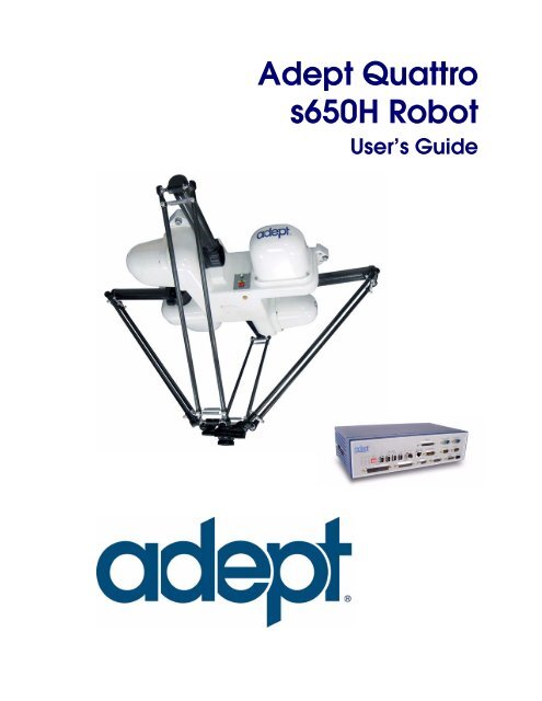
<strong>Adept</strong> <strong>Quattro</strong><br />
<strong>s650H</strong> <strong>Robot</strong><br />
User’s Guide
<strong>Adept</strong> <strong>Quattro</strong><br />
<strong>s650H</strong> <strong>Robot</strong><br />
User’s Guide<br />
P/N: 09313-000, Rev A<br />
October, 2008<br />
3011 Triad Drive • Livermore, CA 94551 • USA • Phone 925.245.3400 • Fax 925.960.0452<br />
Otto-Hahn-Strasse 23 • 44227 Dortmund • Germany • Phone +49.231.75.89.40 • Fax +49.231.75.89.450<br />
151 Lorong Chuan #04-07 • New Tech Park, Lobby G • Singapore 556741 • Phone +65.6281.5731 • Fax +65.6280.5714
The information contained herein is the property of <strong>Adept</strong> Technology, Inc., and shall not be reproduced<br />
in whole or in part without prior written approval of <strong>Adept</strong> Technology, Inc. The information<br />
herein is subject to change without notice and should not be construed as a commitment by<br />
<strong>Adept</strong> Technology, Inc. This manual is periodically reviewed and revised.<br />
<strong>Adept</strong> Technology, Inc., assumes no responsibility for any errors or omissions in this document.<br />
Critical evaluation of this manual by the user is welcomed. Your comments assist us in preparation<br />
of future documentation. Please email your comments to: techpubs@adept.com.<br />
Copyright ©2007, 2008 by <strong>Adept</strong> Technology, Inc. All rights reserved.<br />
<strong>Adept</strong>, the <strong>Adept</strong> logo, the <strong>Adept</strong> Technology logo, <strong>Adept</strong>Vision, AIM, Blox, Bloxview, FireBlox,<br />
Fireview, HexSight, Meta Controls, MetaControls, Metawire, Soft Machines, and Visual Machines<br />
are registered trademarks of <strong>Adept</strong> Technology, Inc.<br />
Brain on Board is a registered trademark of <strong>Adept</strong> Technology, Inc. in Germany.<br />
ACE, <strong>Adept</strong> 1060 / 1060+, <strong>Adept</strong> 1850 / 1850 XP, <strong>Adept</strong> 540 <strong>Adept</strong> 560, <strong>Adept</strong> AnyFeeder,<br />
<strong>Adept</strong> Award, <strong>Adept</strong> C40, <strong>Adept</strong> C60, <strong>Adept</strong> CC, <strong>Adept</strong> Cobra 350, <strong>Adept</strong> Cobra 350 CR/ESD,<br />
<strong>Adept</strong> Cobra 550, <strong>Adept</strong> 550 CleanRoom, <strong>Adept</strong> Cobra 600, <strong>Adept</strong> Cobra 800, <strong>Adept</strong> Cobra i600,<br />
<strong>Adept</strong> Cobra i800, <strong>Adept</strong> Cobra PLC server, <strong>Adept</strong> Cobra PLC800, <strong>Adept</strong> Cobra s600, <strong>Adept</strong> Cobra<br />
s800, <strong>Adept</strong> Cobra s800 Inverted, <strong>Adept</strong> Cobra Smart600, <strong>Adept</strong> Cobra Smart800, <strong>Adept</strong> DeskTop,<br />
<strong>Adept</strong> FFE, <strong>Adept</strong> FlexFeeder 250, <strong>Adept</strong> IC, <strong>Adept</strong> iSight, <strong>Adept</strong> Impulse Feeder,<br />
<strong>Adept</strong> LineVision, <strong>Adept</strong> MB-10 ServoKit, <strong>Adept</strong> MC, <strong>Adept</strong> MotionBlox-10,<br />
<strong>Adept</strong> MotionBlox-40L, <strong>Adept</strong> MotionBlox-40R, <strong>Adept</strong> MV <strong>Adept</strong> MV-10, <strong>Adept</strong> MV-19,<br />
<strong>Adept</strong> MV4, <strong>Adept</strong> MV-5, <strong>Adept</strong> MV-8, <strong>Adept</strong> OC, <strong>Adept</strong> Python, <strong>Adept</strong> <strong>Quattro</strong> s650,<br />
<strong>Adept</strong> <strong>Quattro</strong> <strong>s650H</strong>, <strong>Adept</strong> sDIO, <strong>Adept</strong> SmartAmp, <strong>Adept</strong> SmartAxis, <strong>Adept</strong> SmartController<br />
CS, <strong>Adept</strong> SmartController CX, <strong>Adept</strong> SmartModule, <strong>Adept</strong> SmartMotion, <strong>Adept</strong> SmartServo,<br />
<strong>Adept</strong> sMI6, <strong>Adept</strong> sSight, <strong>Adept</strong> Viper s650, <strong>Adept</strong> Viper s850, <strong>Adept</strong> Viper s1300, <strong>Adept</strong> Viper<br />
s1700, <strong>Adept</strong> Viper s2000, <strong>Adept</strong>Cartesian, <strong>Adept</strong>Cast, <strong>Adept</strong>Force, <strong>Adept</strong>FTP, <strong>Adept</strong>GEM,<br />
<strong>Adept</strong>Modules, <strong>Adept</strong>Motion, <strong>Adept</strong>Motion Servo, <strong>Adept</strong>Motion VME, <strong>Adept</strong>Net, <strong>Adept</strong>NFS,<br />
<strong>Adept</strong>One, <strong>Adept</strong>One-MV, <strong>Adept</strong>One-XL, <strong>Adept</strong>RAPID, <strong>Adept</strong>Sight, <strong>Adept</strong>Six, <strong>Adept</strong>Six 300,<br />
<strong>Adept</strong>Six 300 CL, <strong>Adept</strong>Six 300 CR, <strong>Adept</strong>Six 600, <strong>Adept</strong>TCP/IP, <strong>Adept</strong>Three, <strong>Adept</strong>Three-MV,<br />
<strong>Adept</strong>Three-XL, <strong>Adept</strong>Two, <strong>Adept</strong>Vision, AVI <strong>Adept</strong>Vision, AGS <strong>Adept</strong>Vision GV, <strong>Adept</strong>Vision<br />
I, <strong>Adept</strong>Vision II, <strong>Adept</strong>Vision VME, <strong>Adept</strong>Vision VXL, <strong>Adept</strong>Vision XGS, <strong>Adept</strong>Vision XGS II,<br />
<strong>Adept</strong>Windows, <strong>Adept</strong>Windows Controller, <strong>Adept</strong>Windows DDE, <strong>Adept</strong>Windows Offline<br />
Editor, <strong>Adept</strong>Windows PC, AIM Command Server, AIM Dispense, AIM PCB, AIM VisionWare,<br />
A-Series, FlexFeedWare, HyperDrive, IO Blox, IO Blox, 88, MicroV+, MotionBlox, MotionWare,<br />
ObjectFinder, ObjectFinder 2000, PackOne, PalletWare, sAVI, S-Series, UltraOne, V, V+ and<br />
VisionTeach are trademarks of <strong>Adept</strong> Technology, Inc.<br />
Any trademarks from other companies used in this publication<br />
are the property of those respective companies.<br />
Printed in the United States of America
Table of Contents<br />
1 Introduction . . . . . . . . . . . . . . . . . . . . . . . . . . . . . . . . . . . . . . . . . . . . . . . 13<br />
1.1 Product Description. . . . . . . . . . . . . . . . . . . . . . . . . . . . . . . . . . . . . . . . . . . . . . . . 13<br />
<strong>Adept</strong> <strong>Quattro</strong> <strong>s650H</strong> <strong>Robot</strong> . . . . . . . . . . . . . . . . . . . . . . . . . . . . . . . . . . . . . . 13<br />
<strong>Quattro</strong> <strong>Robot</strong> Base. . . . . . . . . . . . . . . . . . . . . . . . . . . . . . . . . . . . . . . . . . . . . 14<br />
<strong>Adept</strong> AIB . . . . . . . . . . . . . . . . . . . . . . . . . . . . . . . . . . . . . . . . . . . . . . . . . . . . . 14<br />
Inner Arms . . . . . . . . . . . . . . . . . . . . . . . . . . . . . . . . . . . . . . . . . . . . . . . . . . . . . 15<br />
Ball Joints, Outer Arms . . . . . . . . . . . . . . . . . . . . . . . . . . . . . . . . . . . . . . . . . . . 16<br />
Platform. . . . . . . . . . . . . . . . . . . . . . . . . . . . . . . . . . . . . . . . . . . . . . . . . . . . . . . 16<br />
<strong>Adept</strong> SmartController . . . . . . . . . . . . . . . . . . . . . . . . . . . . . . . . . . . . . . . . . . 20<br />
1.2 Installation Overview . . . . . . . . . . . . . . . . . . . . . . . . . . . . . . . . . . . . . . . . . . . . . . 20<br />
1.3 Manufacturer’s Declaration . . . . . . . . . . . . . . . . . . . . . . . . . . . . . . . . . . . . . . . . . 21<br />
1.4 How Can I Get Help? . . . . . . . . . . . . . . . . . . . . . . . . . . . . . . . . . . . . . . . . . . . . . . 21<br />
Related Manuals . . . . . . . . . . . . . . . . . . . . . . . . . . . . . . . . . . . . . . . . . . . . . . . 22<br />
<strong>Adept</strong> Document Library . . . . . . . . . . . . . . . . . . . . . . . . . . . . . . . . . . . . . . . . 22<br />
2 Safety . . . . . . . . . . . . . . . . . . . . . . . . . . . . . . . . . . . . . . . . . . . . . . . . . . . . 23<br />
2.1 Warnings, Cautions, and Notes in Manual . . . . . . . . . . . . . . . . . . . . . . . . . . . . . 23<br />
2.2 Warning Labels on the <strong>Robot</strong> . . . . . . . . . . . . . . . . . . . . . . . . . . . . . . . . . . . . . . . . 24<br />
2.3 Precautions and Required Safeguards . . . . . . . . . . . . . . . . . . . . . . . . . . . . . . . 24<br />
Safety Barriers . . . . . . . . . . . . . . . . . . . . . . . . . . . . . . . . . . . . . . . . . . . . . . . . . . 24<br />
Impact and Trapping Points . . . . . . . . . . . . . . . . . . . . . . . . . . . . . . . . . . . . . 25<br />
Instructions for Emergency Movement without Drive Power . . . . . . . . . . . 25<br />
Emergency Recovery Procedures . . . . . . . . . . . . . . . . . . . . . . . . . . . . . . . . . 25<br />
Additional Safety Information . . . . . . . . . . . . . . . . . . . . . . . . . . . . . . . . . . . . 25<br />
2.4 Risk Assessment. . . . . . . . . . . . . . . . . . . . . . . . . . . . . . . . . . . . . . . . . . . . . . . . . . . 27<br />
Exposure . . . . . . . . . . . . . . . . . . . . . . . . . . . . . . . . . . . . . . . . . . . . . . . . . . . . . . 27<br />
Severity of Injury . . . . . . . . . . . . . . . . . . . . . . . . . . . . . . . . . . . . . . . . . . . . . . . . 27<br />
Slow Speed Control Function and Testing . . . . . . . . . . . . . . . . . . . . . . . . . . 28<br />
2.5 Intended Use of the <strong>Robot</strong>s . . . . . . . . . . . . . . . . . . . . . . . . . . . . . . . . . . . . . . . . . 29<br />
2.6 <strong>Robot</strong> Modifications . . . . . . . . . . . . . . . . . . . . . . . . . . . . . . . . . . . . . . . . . . . . . . . 30<br />
Acceptable Modifications . . . . . . . . . . . . . . . . . . . . . . . . . . . . . . . . . . . . . . . 30<br />
Unacceptable Modifications . . . . . . . . . . . . . . . . . . . . . . . . . . . . . . . . . . . . 30<br />
2.7 Transport. . . . . . . . . . . . . . . . . . . . . . . . . . . . . . . . . . . . . . . . . . . . . . . . . . . . . . . . . 31<br />
2.8 Safety Requirements for Additional Equipment . . . . . . . . . . . . . . . . . . . . . . . . . 31<br />
2.9 Sound Emissions . . . . . . . . . . . . . . . . . . . . . . . . . . . . . . . . . . . . . . . . . . . . . . . . . . 31<br />
2.10 Thermal Hazard . . . . . . . . . . . . . . . . . . . . . . . . . . . . . . . . . . . . . . . . . . . . . . . . . . 32<br />
<strong>Adept</strong> <strong>Quattro</strong> <strong>s650H</strong> <strong>Robot</strong> User’s Guide, Rev A 5
Table of Contents<br />
2.11 Working Areas . . . . . . . . . . . . . . . . . . . . . . . . . . . . . . . . . . . . . . . . . . . . . . . . . . . 32<br />
2.12 Qualification of Personnel . . . . . . . . . . . . . . . . . . . . . . . . . . . . . . . . . . . . . . . . . . 32<br />
2.13 Safety Equipment for Operators . . . . . . . . . . . . . . . . . . . . . . . . . . . . . . . . . . . . 33<br />
2.14 Protection Against Unauthorized Operation . . . . . . . . . . . . . . . . . . . . . . . . . . . 33<br />
2.15 Safety Aspects While Performing Maintenance . . . . . . . . . . . . . . . . . . . . . . . . 33<br />
2.16 Risks Due to Incorrect Installation or Operation . . . . . . . . . . . . . . . . . . . . . . . . 34<br />
2.17 What to Do in an Emergency . . . . . . . . . . . . . . . . . . . . . . . . . . . . . . . . . . . . . . . 34<br />
3 <strong>Robot</strong> Installation . . . . . . . . . . . . . . . . . . . . . . . . . . . . . . . . . . . . . . . . . . . 35<br />
3.1 Transport and Storage . . . . . . . . . . . . . . . . . . . . . . . . . . . . . . . . . . . . . . . . . . . . . . 35<br />
3.2 Unpacking and Inspecting the <strong>Adept</strong> Equipment . . . . . . . . . . . . . . . . . . . . . . . 35<br />
Before Unpacking . . . . . . . . . . . . . . . . . . . . . . . . . . . . . . . . . . . . . . . . . . . . . . . 35<br />
Unpacking . . . . . . . . . . . . . . . . . . . . . . . . . . . . . . . . . . . . . . . . . . . . . . . . . . . . . 35<br />
Upon Unpacking . . . . . . . . . . . . . . . . . . . . . . . . . . . . . . . . . . . . . . . . . . . . . . . . 37<br />
3.3 Repacking for Relocation . . . . . . . . . . . . . . . . . . . . . . . . . . . . . . . . . . . . . . . . . . . 37<br />
3.4 Environmental and Facility Requirements . . . . . . . . . . . . . . . . . . . . . . . . . . . . . 37<br />
3.5 Mounting Frame . . . . . . . . . . . . . . . . . . . . . . . . . . . . . . . . . . . . . . . . . . . . . . . . . . . 38<br />
Overview . . . . . . . . . . . . . . . . . . . . . . . . . . . . . . . . . . . . . . . . . . . . . . . . . . . . . . 38<br />
Frame Orientation. . . . . . . . . . . . . . . . . . . . . . . . . . . . . . . . . . . . . . . . . . . . . . . 39<br />
Frame Construction . . . . . . . . . . . . . . . . . . . . . . . . . . . . . . . . . . . . . . . . . . . . . 39<br />
<strong>Robot</strong>-to-Frame Considerations . . . . . . . . . . . . . . . . . . . . . . . . . . . . . . . . . . . 39<br />
Gussets . . . . . . . . . . . . . . . . . . . . . . . . . . . . . . . . . . . . . . . . . . . . . . . . . . . . . . . . 40<br />
3.6 Mounting the <strong>Robot</strong> Base . . . . . . . . . . . . . . . . . . . . . . . . . . . . . . . . . . . . . . . . . . . 40<br />
<strong>Robot</strong> Orientation . . . . . . . . . . . . . . . . . . . . . . . . . . . . . . . . . . . . . . . . . . . . . . . 41<br />
Mounting Surfaces . . . . . . . . . . . . . . . . . . . . . . . . . . . . . . . . . . . . . . . . . . . . . . 41<br />
Mounting Options . . . . . . . . . . . . . . . . . . . . . . . . . . . . . . . . . . . . . . . . . . . . . . . 41<br />
Mounting Procedure from Above the Frame . . . . . . . . . . . . . . . . . . . . . . . . 41<br />
Mounting Procedure from Below the Frame . . . . . . . . . . . . . . . . . . . . . . . . . 43<br />
Install Mounting Hardware. . . . . . . . . . . . . . . . . . . . . . . . . . . . . . . . . . . . . . . . 44<br />
3.7 Attaching the Outer Arms and Platform . . . . . . . . . . . . . . . . . . . . . . . . . . . . . . . 45<br />
Clocking the Platform to the Base . . . . . . . . . . . . . . . . . . . . . . . . . . . . . . . . . 45<br />
Attaching the Outer Arms . . . . . . . . . . . . . . . . . . . . . . . . . . . . . . . . . . . . . . . . 46<br />
4 System Installation . . . . . . . . . . . . . . . . . . . . . . . . . . . . . . . . . . . . . . . . . . 51<br />
4.1 System Cable Diagram . . . . . . . . . . . . . . . . . . . . . . . . . . . . . . . . . . . . . . . . . . . . 51<br />
4.2 Cable Parts List . . . . . . . . . . . . . . . . . . . . . . . . . . . . . . . . . . . . . . . . . . . . . . . . . . . . 52<br />
4.3 Installing the SmartController . . . . . . . . . . . . . . . . . . . . . . . . . . . . . . . . . . . . . . . . 52<br />
4.4 Description of Connectors on <strong>Robot</strong> Interface Panel . . . . . . . . . . . . . . . . . . . . 53<br />
4.5 Cable Connections from <strong>Robot</strong> to SmartController . . . . . . . . . . . . . . . . . . . . . . 54<br />
6 <strong>Adept</strong> <strong>Quattro</strong> <strong>s650H</strong> <strong>Robot</strong> User’s Guide, Rev A
Table of Contents<br />
4.6 Connecting 24 VDC Power to <strong>Robot</strong> . . . . . . . . . . . . . . . . . . . . . . . . . . . . . . . . . 54<br />
Specifications for 24 VDC <strong>Robot</strong> and Controller Power . . . . . . . . . . . . . . . 54<br />
Details for 24 VDC Mating Connector . . . . . . . . . . . . . . . . . . . . . . . . . . . . . 55<br />
Procedure for Creating 24 VDC Cable . . . . . . . . . . . . . . . . . . . . . . . . . . . . 55<br />
Installing 24 VDC <strong>Robot</strong> Cable. . . . . . . . . . . . . . . . . . . . . . . . . . . . . . . . . . . . 56<br />
4.7 Connecting 200-240 VAC Power to <strong>Robot</strong> . . . . . . . . . . . . . . . . . . . . . . . . . . . . . 57<br />
Specifications for AC Power . . . . . . . . . . . . . . . . . . . . . . . . . . . . . . . . . . . . . 57<br />
Details for AC Mating Connector . . . . . . . . . . . . . . . . . . . . . . . . . . . . . . . . . 59<br />
Procedure for Creating 200-240 VAC Cable . . . . . . . . . . . . . . . . . . . . . . . . 59<br />
Installing AC Power Cable to <strong>Robot</strong> . . . . . . . . . . . . . . . . . . . . . . . . . . . . . . . 60<br />
4.8 Grounding the <strong>Adept</strong> <strong>Quattro</strong> <strong>s650H</strong> <strong>Robot</strong> System . . . . . . . . . . . . . . . . . . . . . 60<br />
<strong>Robot</strong>-Mounted Equipment Grounding . . . . . . . . . . . . . . . . . . . . . . . . . . . . 60<br />
4.9 Installing User-Supplied Safety Equipment . . . . . . . . . . . . . . . . . . . . . . . . . . . . 61<br />
5 System Operation . . . . . . . . . . . . . . . . . . . . . . . . . . . . . . . . . . . . . . . . . . 63<br />
5.1 <strong>Robot</strong> Status Display Panel . . . . . . . . . . . . . . . . . . . . . . . . . . . . . . . . . . . . . . . . . 63<br />
5.2 Status Panel Fault Codes . . . . . . . . . . . . . . . . . . . . . . . . . . . . . . . . . . . . . . . . . . . 64<br />
5.3 Using the Brake Release Button . . . . . . . . . . . . . . . . . . . . . . . . . . . . . . . . . . . . . . 64<br />
Brakes . . . . . . . . . . . . . . . . . . . . . . . . . . . . . . . . . . . . . . . . . . . . . . . . . . . . . . . . 64<br />
Brake Release Button. . . . . . . . . . . . . . . . . . . . . . . . . . . . . . . . . . . . . . . . . . . . 65<br />
5.4 Connecting Digital I/O to the System . . . . . . . . . . . . . . . . . . . . . . . . . . . . . . . . . 65<br />
5.5 Using Digital I/O on <strong>Robot</strong> XIO Connector . . . . . . . . . . . . . . . . . . . . . . . . . . . . 67<br />
XIO Input Signals. . . . . . . . . . . . . . . . . . . . . . . . . . . . . . . . . . . . . . . . . . . . . . . . 69<br />
XIO Breakout Cable . . . . . . . . . . . . . . . . . . . . . . . . . . . . . . . . . . . . . . . . . . . . 72<br />
5.6 Commissioning the System . . . . . . . . . . . . . . . . . . . . . . . . . . . . . . . . . . . . . . . . . 73<br />
Verifying Installation . . . . . . . . . . . . . . . . . . . . . . . . . . . . . . . . . . . . . . . . . . . . 74<br />
System Start-up Procedure . . . . . . . . . . . . . . . . . . . . . . . . . . . . . . . . . . . . . . 75<br />
Verifying E-Stop Functions . . . . . . . . . . . . . . . . . . . . . . . . . . . . . . . . . . . . . . . . 76<br />
Verifying <strong>Robot</strong> Motions. . . . . . . . . . . . . . . . . . . . . . . . . . . . . . . . . . . . . . . . . . 76<br />
5.7 <strong>Quattro</strong> Motions. . . . . . . . . . . . . . . . . . . . . . . . . . . . . . . . . . . . . . . . . . . . . . . . . . . 76<br />
Straight-line Motion . . . . . . . . . . . . . . . . . . . . . . . . . . . . . . . . . . . . . . . . . . . . . 76<br />
Containment Obstacles . . . . . . . . . . . . . . . . . . . . . . . . . . . . . . . . . . . . . . . . . 77<br />
Tool Flange Rotation Extremes . . . . . . . . . . . . . . . . . . . . . . . . . . . . . . . . . . . . 77<br />
5.8 Learning to Program the <strong>Adept</strong> <strong>Quattro</strong> <strong>Robot</strong> . . . . . . . . . . . . . . . . . . . . . . . . . 79<br />
<strong>Adept</strong> <strong>Quattro</strong> <strong>s650H</strong> <strong>Robot</strong> User’s Guide, Rev A 7
Table of Contents<br />
6 Optional Equipment Installation . . . . . . . . . . . . . . . . . . . . . . . . . . . . . . . 81<br />
6.1 End-Effectors. . . . . . . . . . . . . . . . . . . . . . . . . . . . . . . . . . . . . . . . . . . . . . . . . . . . . . 81<br />
Attaching . . . . . . . . . . . . . . . . . . . . . . . . . . . . . . . . . . . . . . . . . . . . . . . . . . . . . . 81<br />
Aligning . . . . . . . . . . . . . . . . . . . . . . . . . . . . . . . . . . . . . . . . . . . . . . . . . . . . . . . 81<br />
Grounding . . . . . . . . . . . . . . . . . . . . . . . . . . . . . . . . . . . . . . . . . . . . . . . . . . . . . 81<br />
Accessing Vacuum. . . . . . . . . . . . . . . . . . . . . . . . . . . . . . . . . . . . . . . . . . . . . . 81<br />
6.2 Routing End-effector Lines. . . . . . . . . . . . . . . . . . . . . . . . . . . . . . . . . . . . . . . . . . . 82<br />
7 Technical Specifications . . . . . . . . . . . . . . . . . . . . . . . . . . . . . . . . . . . . . 83<br />
7.1 Dimension Drawings . . . . . . . . . . . . . . . . . . . . . . . . . . . . . . . . . . . . . . . . . . . . . . . 83<br />
7.2 <strong>Adept</strong> <strong>Quattro</strong> <strong>s650H</strong> <strong>Robot</strong> Internal Connections . . . . . . . . . . . . . . . . . . . . . . . 87<br />
7.3 XSLV Connector . . . . . . . . . . . . . . . . . . . . . . . . . . . . . . . . . . . . . . . . . . . . . . . . . . . 88<br />
7.4 <strong>Robot</strong> Specifications . . . . . . . . . . . . . . . . . . . . . . . . . . . . . . . . . . . . . . . . . . . . . . . 89<br />
7.5 Platform Specifications . . . . . . . . . . . . . . . . . . . . . . . . . . . . . . . . . . . . . . . . . . . . . 90<br />
Torque and Rotation Limits. . . . . . . . . . . . . . . . . . . . . . . . . . . . . . . . . . . . . . . . 90<br />
Payload Inertia vs. Acceleration. . . . . . . . . . . . . . . . . . . . . . . . . . . . . . . . . . . 90<br />
7.6 <strong>Robot</strong> Mounting Frame . . . . . . . . . . . . . . . . . . . . . . . . . . . . . . . . . . . . . . . . . . . . . 90<br />
8 Maintenance . . . . . . . . . . . . . . . . . . . . . . . . . . . . . . . . . . . . . . . . . . . . . . 95<br />
8.1 Periodic Maintenance Schedule . . . . . . . . . . . . . . . . . . . . . . . . . . . . . . . . . . . . . 95<br />
8.2 Checking Safety Systems . . . . . . . . . . . . . . . . . . . . . . . . . . . . . . . . . . . . . . . . . . . 97<br />
8.3 Checking <strong>Robot</strong> Mounting Bolts . . . . . . . . . . . . . . . . . . . . . . . . . . . . . . . . . . . . . . 98<br />
8.4 Checking <strong>Robot</strong> Gear Drives . . . . . . . . . . . . . . . . . . . . . . . . . . . . . . . . . . . . . . . . 98<br />
8.5 Checking Fan Operation . . . . . . . . . . . . . . . . . . . . . . . . . . . . . . . . . . . . . . . . . . . 98<br />
8.6 Replacing the AIB Chassis . . . . . . . . . . . . . . . . . . . . . . . . . . . . . . . . . . . . . . . . . . 99<br />
Removing the AIB Chassis . . . . . . . . . . . . . . . . . . . . . . . . . . . . . . . . . . . . . . . . 99<br />
Installing a New AIB Chassis . . . . . . . . . . . . . . . . . . . . . . . . . . . . . . . . . . . . . . 102<br />
8.7 Replacing the Encoder Battery. . . . . . . . . . . . . . . . . . . . . . . . . . . . . . . . . . . . . . 103<br />
Battery Replacement Interval . . . . . . . . . . . . . . . . . . . . . . . . . . . . . . . . . . . . 103<br />
Battery Replacement Procedure . . . . . . . . . . . . . . . . . . . . . . . . . . . . . . . . . 103<br />
8.8 Replacing a Platform . . . . . . . . . . . . . . . . . . . . . . . . . . . . . . . . . . . . . . . . . . . . . . 105<br />
Replacement . . . . . . . . . . . . . . . . . . . . . . . . . . . . . . . . . . . . . . . . . . . . . . . . . 105<br />
Configuration . . . . . . . . . . . . . . . . . . . . . . . . . . . . . . . . . . . . . . . . . . . . . . . . . 106<br />
8 <strong>Adept</strong> <strong>Quattro</strong> <strong>s650H</strong> <strong>Robot</strong> User’s Guide, Rev A
Table of Contents<br />
9 <strong>Robot</strong> Cleaning/ Environmental Concerns . . . . . . . . . . . . . . . . . . . . . 109<br />
9.1 Ambient Environment . . . . . . . . . . . . . . . . . . . . . . . . . . . . . . . . . . . . . . . . . . . . . 109<br />
Humidity . . . . . . . . . . . . . . . . . . . . . . . . . . . . . . . . . . . . . . . . . . . . . . . . . . . . . 109<br />
Temperature . . . . . . . . . . . . . . . . . . . . . . . . . . . . . . . . . . . . . . . . . . . . . . . . . . 110<br />
9.2 Cleaning . . . . . . . . . . . . . . . . . . . . . . . . . . . . . . . . . . . . . . . . . . . . . . . . . . . . . . . 110<br />
Caustic Compatibility . . . . . . . . . . . . . . . . . . . . . . . . . . . . . . . . . . . . . . . . . . 110<br />
Water Shedding . . . . . . . . . . . . . . . . . . . . . . . . . . . . . . . . . . . . . . . . . . . . . . . 111<br />
Wipe-Down . . . . . . . . . . . . . . . . . . . . . . . . . . . . . . . . . . . . . . . . . . . . . . . . . . . 111<br />
9.3 Cleanroom Classification. . . . . . . . . . . . . . . . . . . . . . . . . . . . . . . . . . . . . . . . . . 111<br />
9.4 Design Factors . . . . . . . . . . . . . . . . . . . . . . . . . . . . . . . . . . . . . . . . . . . . . . . . . . . 112<br />
<strong>Robot</strong> Base and Components . . . . . . . . . . . . . . . . . . . . . . . . . . . . . . . . . . . 112<br />
Inner Arms . . . . . . . . . . . . . . . . . . . . . . . . . . . . . . . . . . . . . . . . . . . . . . . . . . . . 112<br />
Ball Joints. . . . . . . . . . . . . . . . . . . . . . . . . . . . . . . . . . . . . . . . . . . . . . . . . . . . . 112<br />
Outer Arms . . . . . . . . . . . . . . . . . . . . . . . . . . . . . . . . . . . . . . . . . . . . . . . . . . . 113<br />
Springs . . . . . . . . . . . . . . . . . . . . . . . . . . . . . . . . . . . . . . . . . . . . . . . . . . . . . . . 113<br />
Platforms . . . . . . . . . . . . . . . . . . . . . . . . . . . . . . . . . . . . . . . . . . . . . . . . . . . . . 113<br />
9.5 Installing Cable Seal Kit . . . . . . . . . . . . . . . . . . . . . . . . . . . . . . . . . . . . . . . . . . . 113<br />
Overview. . . . . . . . . . . . . . . . . . . . . . . . . . . . . . . . . . . . . . . . . . . . . . . . . . . . . 113<br />
Installation Procedure . . . . . . . . . . . . . . . . . . . . . . . . . . . . . . . . . . . . . . . . . . 114<br />
<strong>Adept</strong> <strong>Quattro</strong> <strong>s650H</strong> <strong>Robot</strong> User’s Guide, Rev A 9
List of Figures<br />
Figure 1-1. <strong>Adept</strong> <strong>Quattro</strong> <strong>s650H</strong> <strong>Robot</strong> . . . . . . . . . . . . . . . . . . . . . . . . . . . . . . . . . . . . . . 13<br />
Figure 1-2. Major <strong>Robot</strong> Components, Isometric View . . . . . . . . . . . . . . . . . . . . . . . . . . 14<br />
Figure 1-3. <strong>Adept</strong> AIB . . . . . . . . . . . . . . . . . . . . . . . . . . . . . . . . . . . . . . . . . . . . . . . . . . . . . . 15<br />
Figure 1-4. <strong>Robot</strong> Inner Arm . . . . . . . . . . . . . . . . . . . . . . . . . . . . . . . . . . . . . . . . . . . . . . . . 15<br />
Figure 1-5. Ball Joints between Inner and Outer Arms . . . . . . . . . . . . . . . . . . . . . . . . . . . 16<br />
Figure 1-6. 185° Platform, Top View . . . . . . . . . . . . . . . . . . . . . . . . . . . . . . . . . . . . . . . . . . 18<br />
Figure 1-7. 185° Platform, Bottom View . . . . . . . . . . . . . . . . . . . . . . . . . . . . . . . . . . . . . . . 18<br />
Figure 1-8. 60° Platform, Top View . . . . . . . . . . . . . . . . . . . . . . . . . . . . . . . . . . . . . . . . . . . 19<br />
Figure 1-9. 60° Platform, Bottom View . . . . . . . . . . . . . . . . . . . . . . . . . . . . . . . . . . . . . . . . 19<br />
Figure 1-10. <strong>Adept</strong> SmartController CX . . . . . . . . . . . . . . . . . . . . . . . . . . . . . . . . . . . . . . . . 20<br />
Figure 2-1. Electrical and Thermal Warning Labels on AIB Chassis . . . . . . . . . . . . . . . . . 24<br />
Figure 3-1. <strong>Quattro</strong> Shipping Crate . . . . . . . . . . . . . . . . . . . . . . . . . . . . . . . . . . . . . . . . . . 36<br />
Figure 3-2. Crate with Front Panel/Sides Removed . . . . . . . . . . . . . . . . . . . . . . . . . . . . . 36<br />
Figure 3-3. Sample <strong>Quattro</strong> Mounting Frame . . . . . . . . . . . . . . . . . . . . . . . . . . . . . . . . . . 38<br />
Figure 3-4. Location of Slings for Lifting <strong>Robot</strong> Base . . . . . . . . . . . . . . . . . . . . . . . . . . . . . 42<br />
Figure 3-5. Major <strong>Robot</strong> Components, Top View . . . . . . . . . . . . . . . . . . . . . . . . . . . . . . . 45<br />
Figure 3-6. Platform Orientation Labeling . . . . . . . . . . . . . . . . . . . . . . . . . . . . . . . . . . . . . 46<br />
Figure 3-7. Inner Arm Ball Studs . . . . . . . . . . . . . . . . . . . . . . . . . . . . . . . . . . . . . . . . . . . . . . 47<br />
Figure 3-8. Ball Joint Assembly . . . . . . . . . . . . . . . . . . . . . . . . . . . . . . . . . . . . . . . . . . . . . . 47<br />
Figure 3-9. Installing Ball Joints . . . . . . . . . . . . . . . . . . . . . . . . . . . . . . . . . . . . . . . . . . . . . . 48<br />
Figure 3-10. Spring Hook Gap Dimension . . . . . . . . . . . . . . . . . . . . . . . . . . . . . . . . . . . . . . 49<br />
Figure 3-11. Spring Hook in Bushing . . . . . . . . . . . . . . . . . . . . . . . . . . . . . . . . . . . . . . . . . . . 49<br />
Figure 4-1. System Cable Diagram . . . . . . . . . . . . . . . . . . . . . . . . . . . . . . . . . . . . . . . . . . 51<br />
Figure 4-2. <strong>Robot</strong> Interface Panel . . . . . . . . . . . . . . . . . . . . . . . . . . . . . . . . . . . . . . . . . . . 53<br />
Figure 4-3. User-Supplied 24 VDC Cable . . . . . . . . . . . . . . . . . . . . . . . . . . . . . . . . . . . . . . 56<br />
Figure 4-4. Typical AC Power Installation with Single-Phase Supply . . . . . . . . . . . . . . . . 58<br />
Figure 4-5. Single-Phase AC Power Installation from a Three-Phase AC Supply . . . . . . 59<br />
Figure 4-6. AC Power Mating Connector . . . . . . . . . . . . . . . . . . . . . . . . . . . . . . . . . . . . . 60<br />
Figure 5-1. <strong>Robot</strong> Status Display Panel . . . . . . . . . . . . . . . . . . . . . . . . . . . . . . . . . . . . . . . . 63<br />
Figure 5-2. Connecting Digital I/O to the System . . . . . . . . . . . . . . . . . . . . . . . . . . . . . . . 66<br />
Figure 5-3. Typical User Wiring for XIO Input Signals . . . . . . . . . . . . . . . . . . . . . . . . . . . . . 70<br />
Figure 5-4. Typical User Wiring for XIO Output Signals . . . . . . . . . . . . . . . . . . . . . . . . . . . 72<br />
Figure 5-5. Optional XIO Breakout Cable . . . . . . . . . . . . . . . . . . . . . . . . . . . . . . . . . . . . . 72<br />
Figure 5-6. Typical Startup Screen . . . . . . . . . . . . . . . . . . . . . . . . . . . . . . . . . . . . . . . . . . . 75<br />
Figure 5-7. 185° Platform Ambiguity Zones . . . . . . . . . . . . . . . . . . . . . . . . . . . . . . . . . . . . 78<br />
Figure 5-8. Invalid Move . . . . . . . . . . . . . . . . . . . . . . . . . . . . . . . . . . . . . . . . . . . . . . . . . . . 78<br />
Figure 5-9. Valid Move . . . . . . . . . . . . . . . . . . . . . . . . . . . . . . . . . . . . . . . . . . . . . . . . . . . . . 79<br />
Figure 7-1. Top Dimensions, Work Envelope, and Mounting Hole Pattern . . . . . . . . . . 83<br />
Figure 7-2. Work Envelope, Side View . . . . . . . . . . . . . . . . . . . . . . . . . . . . . . . . . . . . . . . . 84<br />
<strong>Adept</strong> <strong>Quattro</strong> <strong>s650H</strong> <strong>Robot</strong> User’s Guide, Rev A 11
List of Figures<br />
Figure 7-3. Tool Flange Dimensions, 60° Platform . . . . . . . . . . . . . . . . . . . . . . . . . . . . . . . 85<br />
Figure 7-4. Tool Flange Dimensions, 185° Platform . . . . . . . . . . . . . . . . . . . . . . . . . . . . . . 85<br />
Figure 7-5. Arm Travel Volume . . . . . . . . . . . . . . . . . . . . . . . . . . . . . . . . . . . . . . . . . . . . . . . 86<br />
Figure 7-6. <strong>Robot</strong> Internal Connections Diagram . . . . . . . . . . . . . . . . . . . . . . . . . . . . . . . 87<br />
Figure 7-7. Mounting Frame, Orthogonal View . . . . . . . . . . . . . . . . . . . . . . . . . . . . . . . . . 91<br />
Figure 7-8. Mounting Frame, Side View 1 . . . . . . . . . . . . . . . . . . . . . . . . . . . . . . . . . . . . . . 92<br />
Figure 7-9. Mounting Frame, Side View 2 . . . . . . . . . . . . . . . . . . . . . . . . . . . . . . . . . . . . . . 92<br />
Figure 7-10. Mounting Frame, Detail 1 . . . . . . . . . . . . . . . . . . . . . . . . . . . . . . . . . . . . . . . . . 93<br />
Figure 7-11. Mounting Frame, Detail 2 . . . . . . . . . . . . . . . . . . . . . . . . . . . . . . . . . . . . . . . . . 93<br />
Figure 7-12. Mounting Frame, Top View . . . . . . . . . . . . . . . . . . . . . . . . . . . . . . . . . . . . . . . . 94<br />
Figure 8-1. Securing Screw on AIB Chassis . . . . . . . . . . . . . . . . . . . . . . . . . . . . . . . . . . . . 100<br />
Figure 8-2. Opening the AIB Chassis . . . . . . . . . . . . . . . . . . . . . . . . . . . . . . . . . . . . . . . . . 100<br />
Figure 8-3. Connectors on AIB Chassis . . . . . . . . . . . . . . . . . . . . . . . . . . . . . . . . . . . . . . . 101<br />
Figure 8-4. Ground Screw on AIB Chassis . . . . . . . . . . . . . . . . . . . . . . . . . . . . . . . . . . . . . 101<br />
Figure 8-5. Status Display Panel, Showing 4 hex-head Screws . . . . . . . . . . . . . . . . . . . . 104<br />
Figure 8-6. Battery Bracket on Status Display Panel . . . . . . . . . . . . . . . . . . . . . . . . . . . . 104<br />
Figure 8-7. SPEC Utility Load Function . . . . . . . . . . . . . . . . . . . . . . . . . . . . . . . . . . . . . . . . 107<br />
Figure 8-8. SPEC Save Specification Menu . . . . . . . . . . . . . . . . . . . . . . . . . . . . . . . . . . . 108<br />
Figure 9-1. AIB and Base, Showing Non-anodized Aluminum . . . . . . . . . . . . . . . . . . . . 110<br />
Figure 9-2. Joint, Between AIB and Base, to be Caulked . . . . . . . . . . . . . . . . . . . . . . . . 111<br />
Figure 9-3. AIB Cable Seal Housing (left), Installed (right) . . . . . . . . . . . . . . . . . . . . . . . 114<br />
Figure 9-4. Cable Entry Top Cover Assembly . . . . . . . . . . . . . . . . . . . . . . . . . . . . . . . . . . 115<br />
Figure 9-5. Bottom of Cable Entry Top Cover, CF Frame . . . . . . . . . . . . . . . . . . . . . . . . 115<br />
Figure 9-6. Adapting a Module to the Cable Size, Checking the Gap . . . . . . . . . . . . 115<br />
Figure 9-7. Greasing a Roxtec Module . . . . . . . . . . . . . . . . . . . . . . . . . . . . . . . . . . . . . . . 116<br />
Figure 9-8. Installing Roxtec Modules into the Frame . . . . . . . . . . . . . . . . . . . . . . . . . . . 116<br />
Figure 9-9. Tightening the Compression Unit . . . . . . . . . . . . . . . . . . . . . . . . . . . . . . . . . . 116<br />
Figure 9-10. Cable Entry Assembly with Cables . . . . . . . . . . . . . . . . . . . . . . . . . . . . . . . . . 117<br />
Figure 9-11. Ground Lug Attachment on the AIB . . . . . . . . . . . . . . . . . . . . . . . . . . . . . . . 117<br />
Figure 9-12. Installing Cable Entry Top Cover Assembly . . . . . . . . . . . . . . . . . . . . . . . . . . 118<br />
12 <strong>Adept</strong> <strong>Quattro</strong> <strong>s650H</strong> <strong>Robot</strong> User’s Guide, Rev A
Introduction 1<br />
1.1 Product Description<br />
<strong>Adept</strong> <strong>Quattro</strong> <strong>s650H</strong> <strong>Robot</strong><br />
The <strong>Adept</strong> <strong>Quattro</strong> <strong>s650H</strong> robot is a four-axis parallel robot. The four identical axis motors<br />
control movement of the robot tool in X, Y, and Z directions, as well as Theta rotation. See<br />
Figure 1-1.<br />
The <strong>Adept</strong> <strong>Quattro</strong> <strong>s650H</strong> robot requires an <strong>Adept</strong> SmartController CX for operation. The<br />
robot is user-programmed and controlled using the SmartController.<br />
NOTE: The <strong>Adept</strong> SmartController CX must be installed inside a NEMA-1<br />
rated enclosure.<br />
The robot servo code runs on an <strong>Adept</strong> SmartServo distributed-motion control platform<br />
embedded in the robot base.<br />
Mechanical specifications for the <strong>Adept</strong> <strong>Quattro</strong> <strong>s650H</strong> robot are provided in Chapter 7.<br />
Figure 1-1. <strong>Adept</strong> <strong>Quattro</strong> <strong>s650H</strong> <strong>Robot</strong><br />
<strong>Adept</strong> <strong>Quattro</strong> <strong>s650H</strong> <strong>Robot</strong> User’s Guide, Rev A 13
Chapter 1 - Introduction<br />
Cable Cover<br />
(IP-66 option)<br />
AIB<br />
Base<br />
Inner<br />
Arms<br />
Mounting<br />
Pads<br />
Motor<br />
Cover<br />
<strong>Quattro</strong> <strong>Robot</strong> Base<br />
Figure 1-2. Major <strong>Robot</strong> Components, Isometric View<br />
The <strong>Adept</strong> <strong>Quattro</strong> <strong>s650H</strong> robot base is an aluminum casting that houses the four drive<br />
motors, and supports the AIB (Amplifiers-In-Base). It provides four mounting pads for<br />
attaching the base to a rigid support frame. The Status Display Panel is mounted on the<br />
side of the robot base.<br />
<strong>Adept</strong> AIB<br />
Outer<br />
Arms<br />
The power amplifiers for the <strong>Adept</strong> <strong>Quattro</strong> <strong>s650H</strong> robot are embedded in the base of the<br />
robot. This amplifier section is known as the AIB distributed motion control platform, and<br />
provides closed-loop servo control of the robot amplifiers, as well as robot I/O.<br />
<strong>Adept</strong> AIB features:<br />
• On-board digital I/O: 12 inputs, 8 outputs<br />
• Low EMI for use with noise-sensitive equipment<br />
•No external fan<br />
• 8 kHz servo rate<br />
• Sine-wave commutation<br />
• Digital feed-forward design<br />
• Temperature sensors on all amplifiers and motors<br />
Ball Joints<br />
(springs not<br />
shown)<br />
Platform<br />
(springs not<br />
shown)<br />
14 <strong>Adept</strong> <strong>Quattro</strong> <strong>s650H</strong> <strong>Robot</strong> User’s Guide, Rev A
Product Description<br />
Figure 1-3. <strong>Adept</strong> AIB<br />
Inner Arms<br />
The four robot motors attach directly to the inner arms through a high-performance gear<br />
reducer. Other than optional, user-supplied hardware mounted on the platform, these are<br />
the only drive motors in the <strong>Quattro</strong>. Figure 1-4 shows a precision carbon fiber assembly<br />
of an inner arm. The RIA-compliant hard stops limit the inner arm motion to -52° and<br />
+124°.<br />
Figure 1-4. <strong>Robot</strong> Inner Arm<br />
<strong>Adept</strong> <strong>Quattro</strong> <strong>s650H</strong> <strong>Robot</strong> User’s Guide, Rev A 15
Chapter 1 - Introduction<br />
Ball Joints, Outer Arms<br />
The inner arm motion is transmitted to the platform through the outer arms, which are<br />
connected between the inner arms and platform with precision ball-joints. The outer arms<br />
are carbon fiber epoxied assemblies with identical ball-joint sockets at each end. A bearing<br />
insert at each socket accepts the ball-joint studs on the inner arms and platform, and<br />
allows for ± 60° of relative motion. No ball-joint lubrication is required. See the following<br />
figure. Refer also to “Ball Joints” on page 112.<br />
Ball Joint Socket<br />
Ball Joint<br />
Socket Insert<br />
Inner Arm<br />
Outer<br />
Arm<br />
Springs<br />
Outer<br />
Arms<br />
Ball Joint Stud<br />
Figure 1-5. Ball Joints between Inner and Outer Arms<br />
Each pair of outer arms is held together with springs that pre-tension the ball joint<br />
assemblies. The outer arms can be installed and removed without tools.<br />
Platform<br />
The platform converts the motion of the four <strong>Quattro</strong> motors into Cartesian motion and<br />
Theta rotation of the robot tool.<br />
Platform articulation is achieved by differentially driving the four motors. Tool rotation is<br />
implemented with either a gear-drive mechanism, or with direct-drive, for applications<br />
needing higher rotation force but less rotation range.<br />
The <strong>Adept</strong> <strong>Quattro</strong> <strong>s650H</strong> robot currently supports two types of platforms, depending on<br />
the amount of Theta rotation and inertia needed.<br />
NOTE: The two platforms require different robot parameters. The 185°<br />
platform is the default. If you have a 60° platform, contact your <strong>Adept</strong><br />
representative.<br />
16 <strong>Adept</strong> <strong>Quattro</strong> <strong>s650H</strong> <strong>Robot</strong> User’s Guide, Rev A
Product Description<br />
The 185° platform (P/N 09068-000) has a rotation range of ±185°, achieved with a gear<br />
drive. This is illustrated in Figure 1-6 and Figure 1-7.<br />
The 60° platform (P/N 09023-000 ) has a rotation range of ± 60°. The tool flange is<br />
mounted directly to the pivot link. It does not rotate in relation to the pivot link, so there<br />
are no gears involved. This is illustrated in Figure 1-8 and Figure 1-9.<br />
NOTE: The 60° platform flange is 27.1 mm higher, in Z, than the previous<br />
1:1 and 4:1 platform flanges. An optional spacer of this thickness is<br />
available, from <strong>Adept</strong>, as P/N 02906-000. The 185° platform is 9.78 mm<br />
higher, in Z. The optional spacer for it is P/N 09266-000.<br />
Refer to “Torque and Rotation Limits” on page 90 for details on rotation and inertial<br />
loading of the platforms.<br />
Both platforms are constructed such that the clocking of the platform relative to the robot<br />
base is critical. This is detailed in “Clocking the Platform to the Base” on page 45.<br />
<strong>Adept</strong> <strong>Quattro</strong> <strong>s650H</strong> <strong>Robot</strong> User’s Guide, Rev A 17
Chapter 1 - Introduction<br />
Figure 1-6. 185° Platform, Top View<br />
Figure 1-7. 185° Platform, Bottom View<br />
18 <strong>Adept</strong> <strong>Quattro</strong> <strong>s650H</strong> <strong>Robot</strong> User’s Guide, Rev A
Product Description<br />
Figure 1-8. 60° Platform, Top View<br />
Figure 1-9. 60° Platform, Bottom View<br />
For shipping:<br />
• The platform and outer arms are removed.<br />
• The platform is shipped pre-assembled as a unit.<br />
You will need to connect the outer arms between the inner arms and the platform<br />
to reassemble the robot. The outer-arm assemblies are interchangeable.<br />
Any end-effectors and their air lines and wiring are user-supplied.<br />
<strong>Adept</strong> <strong>Quattro</strong> <strong>s650H</strong> <strong>Robot</strong> User’s Guide, Rev A 19
R<br />
Chapter 1 - Introduction<br />
<strong>Adept</strong> SmartController<br />
The SmartController is the foundation of <strong>Adept</strong>’s family of high-performance,<br />
distributed-motion and vision controllers. The SmartController is designed for use with:<br />
• <strong>Adept</strong> <strong>Quattro</strong> robots<br />
• <strong>Adept</strong> Cobra s-series robots<br />
• <strong>Adept</strong> Viper s-series robots<br />
• <strong>Adept</strong> Python linear modules<br />
• <strong>Adept</strong> MotionBlox-10<br />
•<strong>Adept</strong> sMI6 (SmartMotion)<br />
The <strong>Adept</strong> SmartController CX supports an integrated vision option and a conveyor<br />
tracking option, as well as other options. It offers scalability and support for IEEE<br />
1394-based digital I/O and general motion expansion modules. The IEEE 1394 interface is<br />
the backbone of the <strong>Adept</strong> SmartServo distributed-servo network, which supports <strong>Adept</strong><br />
products. The controller is commonly programmed through its Fast Ethernet port, which<br />
can be on a distributed network or directly connected to a PC for programming.<br />
*S/N 3562-XXXXX*<br />
CAMERA<br />
RS-232/TERM<br />
RS-422/485<br />
OK HPE LAN<br />
SF ES HD<br />
1 2 3<br />
SmartServo<br />
IEEE-1394<br />
SW1 1.1 1.2 2.1 2.2<br />
1 2 3 4<br />
ON<br />
OFF<br />
XDIO<br />
XUSR<br />
Device Net<br />
Eth 10/100<br />
XSYS<br />
BELT ENCODER<br />
XFP<br />
RS-232-1<br />
XMCP<br />
RS-232-2<br />
XDC1 XDC2<br />
SmartController CX<br />
24V<br />
5A<br />
-+ -+<br />
Figure 1-10. <strong>Adept</strong> SmartController CX<br />
Refer to <strong>Adept</strong> SmartController User’s Guide for SmartController specifications.<br />
1.2 Installation Overview<br />
The system installation process is summarized in the following table. Refer also to the<br />
system cable diagram in Figure 4-1 on page 51.<br />
Table 1-1. Installation Overview<br />
Task to be Performed<br />
Reference Location<br />
1. Mount the robot to a level, stable mounting frame. Section 3.6 on page 40.<br />
2. Attach the robot outer arms and platform. Section 3.7 on page 45.<br />
3. Install the SmartController, Front Panel, Pendant (if<br />
purchased), and <strong>Adept</strong>Windows user interface.<br />
4. Install the IEEE 1394 and XSYS cables between<br />
the robot and SmartController.<br />
Section 4.3 on page 52.<br />
Section 4.5 on page 54.<br />
20 <strong>Adept</strong> <strong>Quattro</strong> <strong>s650H</strong> <strong>Robot</strong> User’s Guide, Rev A
Manufacturer’s Declaration<br />
Table 1-1. Installation Overview<br />
Task to be Performed<br />
5. Create a 24 VDC cable and connect it between the<br />
robot and the user-supplied 24 VDC power supply.<br />
6. Create a 200-240 VAC cable and connect it<br />
between the robot and the facility AC power<br />
source.<br />
Reference Location<br />
Section 4.6 on page 54.<br />
Section 4.7 on page 57.<br />
7. Install user-supplied safety barriers in the workcell. Section 4.9 on page 61.<br />
8. Connect digital I/O through the XIO connector on<br />
the robot.<br />
9. Commission the system, including system start-up<br />
and testing operation.<br />
10.Install optional equipment, including end-effectors,<br />
user air and electrical lines, external equipment,<br />
solenoids, etc.<br />
Section 5.5 on page 67.<br />
Section 5.6 on page 73.<br />
Section 6.1 on page 81.<br />
1.3 Manufacturer’s Declaration<br />
The Manufacturer's Declaration of Incorporation and Conformity for <strong>Adept</strong> robot systems<br />
can be found at the <strong>Adept</strong> website, under the Support section. The URL for the folder is:<br />
ftp://ftp1.adept.com/Download-Library/Manufacturer-Declarations/<br />
Each Manufacturer's Declaration is supplied in PDF format and stored on the website in a<br />
ZIP archive. To access the PDF document:<br />
1. Click on the appropriate .zip file. You are prompted to Open or Save the file.<br />
2. Click Open to open the file and display the archive contents.<br />
3. Double-click on a .pdf file to open it.<br />
1.4 How Can I Get Help?<br />
Refer to the How to Get Help Resource Guide (<strong>Adept</strong> P/N 00961-00700) for details on<br />
getting assistance with your <strong>Adept</strong> software and hardware. Additionally, you can access<br />
information sources on <strong>Adept</strong>’s corporate web site:<br />
http://www.adept.com<br />
<strong>Adept</strong> <strong>Quattro</strong> <strong>s650H</strong> <strong>Robot</strong> User’s Guide, Rev A 21
Chapter 1 - Introduction<br />
Related Manuals<br />
This manual covers the installation, operation, and maintenance of an <strong>Adept</strong> <strong>Quattro</strong><br />
<strong>s650H</strong> robot system. There are additional manuals that cover programming the system,<br />
reconfiguring installed components, and adding optional components. See the following<br />
table. These manuals are available on the <strong>Adept</strong> Document Library CD-ROM shipped<br />
with each system.<br />
Table 1-2. Related Manuals<br />
Manual Title<br />
<strong>Adept</strong> SmartController User’s<br />
Guide<br />
<strong>Adept</strong>Windows Installation<br />
Guide and <strong>Adept</strong>Windows<br />
Online Help<br />
Instructions for <strong>Adept</strong> Utility<br />
Programs<br />
V+ Operating System User’s<br />
Guide<br />
Description<br />
Contains complete information on the installation and operation<br />
of the <strong>Adept</strong> SmartController and the optional sDIO product.<br />
Describes complex network installations, installation and use of<br />
NFS server software, the <strong>Adept</strong>Windows Offline Editor, and the<br />
<strong>Adept</strong>Windows DDE software.<br />
Describes the V+ utility programs used for advanced system<br />
configurations, system upgrades, file copying, and other<br />
operating system configuration procedures.<br />
Describes the V + operating system, including disk file<br />
operations, monitor commands, and monitor command<br />
programs.<br />
V+ Language User’s Guide Describes the V + language and programming of an <strong>Adept</strong><br />
control system.<br />
<strong>Adept</strong> T1 Pendant User’s<br />
Guide<br />
<strong>Adept</strong> T2 Pendant User’s<br />
Guide<br />
<strong>Adept</strong> SmartMotion<br />
Developer’s Guide<br />
Describes use of the optional T1 Manual Control Pendant, P/N<br />
04962-000<br />
Describes use of the optional T2 Manual Control Pendant, P/N<br />
04962-200<br />
Describes the use of <strong>Adept</strong> Utilities, including SPEC. This is<br />
written for the <strong>Adept</strong> SmartMotion system, but is a good source<br />
for SPEC for the <strong>Quattro</strong>, too.<br />
<strong>Adept</strong> Document Library<br />
The <strong>Adept</strong> Document Library (ADL) contains documentation for <strong>Adept</strong> products. You<br />
can access the ADL from:<br />
• the <strong>Adept</strong> Software CD shipped with your system<br />
• the <strong>Adept</strong> web site. Select Document Library from the <strong>Adept</strong> home page. To go<br />
directly to the <strong>Adept</strong> Document Library, type the following URL into your<br />
browser:<br />
http://www.adept.com/Main/KE/DATA/adept_search.htm<br />
To locate information on a specific topic, use the Document Library search engine on the<br />
ADL main page. To view a list of available product documentation, select the Document<br />
Titles option.<br />
22 <strong>Adept</strong> <strong>Quattro</strong> <strong>s650H</strong> <strong>Robot</strong> User’s Guide, Rev A
Safety 2<br />
2.1 Warnings, Cautions, and Notes in Manual<br />
There are six levels of special alert notation used in this manual. In descending order of<br />
importance, they are:<br />
DANGER: This indicates an imminently hazardous<br />
electrical situation which, if not avoided, will result in<br />
death or serious injury.<br />
DANGER: This indicates an imminently hazardous<br />
situation which, if not avoided, will result in death or<br />
serious injury.<br />
WARNING: This indicates a potentially hazardous<br />
electrical situation which, if not avoided, could result in<br />
injury or major damage to the equipment.<br />
WARNING: This indicates a potentially hazardous<br />
situation which, if not avoided, could result in injury or<br />
major damage to the equipment.<br />
CAUTION: This indicates a situation which, if not avoided,<br />
could result in damage to the equipment.<br />
NOTE: This provides supplementary information, emphasizes a point or<br />
procedure, or gives a tip for easier operation.<br />
<strong>Adept</strong> <strong>Quattro</strong> <strong>s650H</strong> <strong>Robot</strong> User’s Guide, Rev A 23
Chapter 2 - Safety<br />
2.2 Warning Labels on the <strong>Robot</strong><br />
The following figure shows the warning labels on the <strong>Adept</strong> <strong>Quattro</strong> <strong>s650H</strong> robot.<br />
Figure 2-1. Electrical and Thermal Warning Labels on AIB Chassis<br />
2.3 Precautions and Required Safeguards<br />
This manual must be read by all personnel who install, operate, or maintain <strong>Adept</strong><br />
systems, or who work within or near the workcell.<br />
WARNING: <strong>Adept</strong> Technology strictly prohibits<br />
installation, commissioning, or operation of an <strong>Adept</strong><br />
robot without adequate safeguards that comply with<br />
applicable local and national standards. Installations in EU<br />
and EEA countries must comply with EN 775/ISO 10218,<br />
especially sections 5,6; EN 292-2; and EN 60204-1,<br />
especially section 13.<br />
Safety Barriers<br />
Safety barriers must be an integral part of robot workcell design. <strong>Adept</strong> systems are<br />
computer-controlled and may activate remote devices under program control at times or<br />
along paths not anticipated by personnel. It is critical that safeguards be in place to<br />
prevent personnel from entering the workcell whenever equipment power is present.<br />
The robot system integrator, or end user, must ensure that adequate safeguards, safety<br />
barriers, light curtains, safety gates, safety floor mats, etc., are installed. The robot<br />
workcell must be designed according to the applicable local and national standards (see<br />
Section 2.8 on page 31).<br />
The safe distance to the robot depends on the height of the safety fence. The height and<br />
the distance of the safety fence from the robot must ensure that personnel cannot reach the<br />
danger zone of the robot.<br />
The <strong>Adept</strong> control system has features that aid the user in constructing system<br />
safeguards, including customer emergency stop circuitry and digital input and output<br />
lines. The emergency power-off circuitry is capable of switching external power systems,<br />
and can be interfaced to the appropriate user-supplied safeguards.<br />
24 <strong>Adept</strong> <strong>Quattro</strong> <strong>s650H</strong> <strong>Robot</strong> User’s Guide, Rev A
Precautions and Required Safeguards<br />
Impact and Trapping Points<br />
<strong>Adept</strong> robots are capable of moving at high speeds. If a person is struck by a robot<br />
(impacted) or trapped (pinched), death or serious injury could occur. <strong>Robot</strong> configuration,<br />
joint speed, joint orientation, and attached payload all contribute to the total amount of<br />
energy available to cause injury.<br />
DANGER: The robot system must be installed to avoid<br />
interference with buildings, structures, utilities, other<br />
machines, and equipment that may create a trapping<br />
hazard or pinch points.<br />
Instructions for Emergency Movement without Drive Power<br />
In an emergency, when AC power is removed from the system but DC power is still<br />
present, the arm can be moved manually. The Brake Release button must be pressed to<br />
enable arm movement. Refer to “Brake Release Button” on page 65.<br />
Emergency Recovery Procedures<br />
In an emergency, follow your internal procedures for emergency recovery of systems.<br />
Additional Safety Information<br />
The standards and regulations listed in this manual contain additional guidelines for<br />
robot system installation, safeguarding, maintenance, testing, startup, and operator<br />
training. Table 2-1 lists some sources for the various standards.<br />
<strong>Adept</strong> <strong>Quattro</strong> <strong>s650H</strong> <strong>Robot</strong> User’s Guide, Rev A 25
Chapter 2 - Safety<br />
Table 2-1. Sources for International Standards and Directives<br />
SEMI International Standards<br />
3081 Zanker Road<br />
San Jose, CA 95134<br />
USA<br />
American National Standards Institute (ANSI)<br />
11 West 42nd Street, 13th Floor<br />
New York, NY 10036<br />
USA<br />
Phone: 408-943-6900<br />
Fax: 408-428-9600<br />
http://www.semi.org<br />
Underwriters Laboratories Inc.<br />
333 Pfingsten Road<br />
Northbrook, IL 60062-2096 USA<br />
Phone: 847-272-8800<br />
Fax: 847-272-8129<br />
http://www.ul.com/info/standard.htm<br />
Global Engineering Documents<br />
15 Inverness Way East<br />
Englewood, CO 80112<br />
USA<br />
Phone 212-642-4900<br />
Fax 212-398-0023<br />
http://www.ansi.org<br />
BSI Group (British Standards)<br />
389 Chiswick High Road<br />
London W4 4AL<br />
United Kingdom<br />
Phone +44 (0)20 8996 9000<br />
Fax +44 (0)20 8996 7400<br />
http://www.bsi-global.com<br />
Document Center, Inc.<br />
1504 Industrial Way, Unit 9<br />
Belmont, CA 94002<br />
USA<br />
Phone 800-854-7179<br />
Fax 303-397-2740<br />
http://global.ihs.com<br />
IEC, International Electrotechnical Commission<br />
Rue de Varembe 3<br />
PO Box 131<br />
CH-1211 Geneva 20<br />
Switzerland<br />
Phone 415-591-7600<br />
Fax 415-591-7617<br />
http://www.document-center.com<br />
<strong>Robot</strong>ic Industries Association (RIA)<br />
900 Victors Way<br />
PO Box 3724<br />
Ann Arbor, MI 48106<br />
USA<br />
Phone +41 22 919-0211<br />
Fax +41 22 919-0300<br />
http://www.iec.ch<br />
Phone 313-994-6088<br />
Fax 313-994-3338<br />
http://www.robotics.org<br />
DIN, Deutsches Institut für Normung e.V.<br />
German Institute for Standardization<br />
Burggrafenstrasse 6<br />
10787 Berlin<br />
Germany<br />
Phone.: +49 30 2601-0<br />
Fax: +49 30 2601-1231<br />
http://www.din.de<br />
http://www2.beuth.de/ (publishing)<br />
26 <strong>Adept</strong> <strong>Quattro</strong> <strong>s650H</strong> <strong>Robot</strong> User’s Guide, Rev A
Risk Assessment<br />
2.4 Risk Assessment<br />
Without special safeguards in its control system, the <strong>Adept</strong> <strong>Quattro</strong> <strong>s650H</strong> robot could<br />
inflict serious injury on an operator working within its work envelope. Safety standards in<br />
some countries require appropriate safety equipment to be installed as part of the system.<br />
Table 2-2 lists some of the safety standards that affect industrial robots. It is not a complete<br />
list. Safeguards must comply with all applicable local and national standards for the<br />
location where the robot is installed.<br />
Table 2-2. Partial List of <strong>Robot</strong> and Machinery Safety Standards<br />
International USA Canada Europe Title of Standard<br />
ISO 10218 EN 775 Manipulating Industrial <strong>Robot</strong>s -<br />
Safety<br />
ANSI/RIA<br />
R15.06<br />
CAN/CSA-<br />
Z434-94<br />
Industrial <strong>Robot</strong>s and <strong>Robot</strong><br />
Systems - Safety Requirements<br />
EN 292-2<br />
EN 954-1<br />
EN 1050<br />
Safety of Machinery - Basic<br />
Concepts, General Principles for<br />
Design<br />
Safety Related Parts of Control<br />
Systems - General Principles for<br />
Design<br />
Safety of Machinery - Risk<br />
Assessment<br />
Exposure<br />
When Arm Power is ON, all personnel must be kept out of the robot work envelope by<br />
interlocked perimeter barriers. The only permitted exception is for teaching the robot in<br />
Manual Mode by a skilled person (see “Qualification of Personnel” on page 32), who must<br />
wear safety equipment (see “Safety Equipment for Operators” on page 33) and carry the<br />
<strong>Adept</strong> pendant. Therefore, exposure of personnel to hazards related to the robot is limited<br />
(seldom and/or short exposure time).<br />
Severity of Injury<br />
Provided that skilled personnel who enter the robot work envelope are wearing<br />
protective headgear, eyeglasses, and safety shoes, it is likely that any injuries caused by<br />
the robot would be slight (normally reversible).<br />
Avoidance<br />
A programmer must always carry the pendant when inside the work envelope, as the<br />
pendant provides both E-Stop and Enabling switch functions.<br />
For normal operation (AUTO mode), user-supplied interlocked guarding must be installed<br />
to prevent any person entering the workcell while arm power is ON.<br />
<strong>Adept</strong> <strong>Quattro</strong> <strong>s650H</strong> <strong>Robot</strong> User’s Guide, Rev A 27
Chapter 2 - Safety<br />
DANGER: The <strong>Adept</strong>-supplied system components<br />
provide a Category 3 E-Stop control system as defined by<br />
EN 954. The robot system must be installed with<br />
user-supplied interlock barriers. The interlocked barrier<br />
must open the E-Stop circuit in the event of personnel<br />
attempting to enter the workcell when Arm Power is<br />
enabled, except for teaching in Manual mode. Failure to<br />
install suitable guarding or interlocks could result in<br />
injury or death.<br />
The E-Stop circuit is Dual Channel (redundant, diverse, and control reliable).<br />
See Figure 7-6 on page 87 for an E-Stop internal circuit diagram.<br />
Slow Speed Control Function and Testing<br />
<strong>Adept</strong> robots can be controlled manually when the operating mode key switch is in the<br />
MANUAL position and the High Power light on the front panel is illuminated. When<br />
Manual mode is selected, motion can only be initiated from the pendant. Per EN 775/ISO<br />
10218, the maximum speed of the robot is limited to 250 mm per second (10 ips) in Manual<br />
mode. It is important to remember that the robot speed is not limited when the robot is in<br />
Automatic (AUTO) mode.<br />
The Risk Assessment for teaching this product depends on the application. In many<br />
applications, the programmer will need to enter the robot workcell while Arm Power is<br />
enabled to teach the robot. Other applications can be designed so that the programmer<br />
does not have to enter the work envelope while Arm Power is ON. Examples of<br />
alternative methods of programming include:<br />
1. Programming from outside the safety barrier.<br />
2. Programming with Arm Power OFF.<br />
3. Copying a program from another (master) robot.<br />
4. Off-line or CAD programming.<br />
Control System Behavior Category<br />
The following paragraphs relate to the requirements of European (EU/EEA) directives for<br />
Machinery, Electric Safety, and Electromagnetic Compatibility (EMC).<br />
In situations with low exposure consideration factors, European Standard EN 1050<br />
specifies use of a Category 1 Control System per EN 954. EN 954 defines a Category 1<br />
Control System as one that employs Category B components designed to withstand<br />
environmental influences, such as voltage, current, temperature, EMI, and well-tried<br />
safety principles. The standard control system described in this guide employs hardware<br />
components in its safety system that meet or exceed the requirements of the EU Machinery<br />
Directive and Low Voltage Directive.<br />
28 <strong>Adept</strong> <strong>Quattro</strong> <strong>s650H</strong> <strong>Robot</strong> User’s Guide, Rev A
Intended Use of the <strong>Robot</strong>s<br />
The standard control system is fully hardened to all EMI influences per the EU EMC<br />
Directive and meets all functional requirements of ISO 10218 (EN 775) Manipulating <strong>Robot</strong>s<br />
Safety. In addition, a software-based reduced speed mode has been incorporated to limit<br />
speed and impact forces on the operator and production tooling when the robot is<br />
operated in Manual Mode.<br />
The standard control system meets or exceeds the requirements imposed by the EN 954<br />
specified Category 1 level of safety.<br />
2.5 Intended Use of the <strong>Robot</strong>s<br />
The installation and use of <strong>Adept</strong> products must comply with all safety instructions and<br />
warnings in this manual. Installation and use must also comply with all applicable local<br />
and national requirements and safety standards (see Section 2.8 on page 31).<br />
The <strong>Adept</strong> <strong>Quattro</strong> <strong>s650H</strong> robot is intended for use in parts assembly and material<br />
handling for payloads of less than 6.0 kg (4.4 lb).<br />
The <strong>Adept</strong> <strong>Quattro</strong> <strong>s650H</strong> robot and the <strong>Adept</strong> SmartController are component<br />
subassemblies of a complete industrial automation system. The controller must be<br />
installed inside a suitable enclosure. The controller must not come into contact with<br />
liquids.<br />
The <strong>Adept</strong> equipment is not intended for use in any of the following situations:<br />
• In hazardous (explosive) atmospheres<br />
• In mobile, portable, marine, or aircraft systems<br />
• In life-support systems<br />
• In residential installations<br />
• In situations where the <strong>Adept</strong> equipment will be subject to extremes of heat or<br />
humidity. See Table 3-1 on page 37 for allowable temperature and humidity<br />
ranges.<br />
WARNING: The instructions for installation, operation,<br />
and maintenance given in this manual must be strictly<br />
observed.<br />
Non-intended use of an <strong>Adept</strong> <strong>Quattro</strong> <strong>s650H</strong> robot can:<br />
• Cause injury to personnel<br />
• Damage the robot or other equipment<br />
• Reduce system reliability and performance<br />
All persons that install, commission, operate, or maintain the robot must:<br />
• Have the necessary qualifications<br />
• Read and follow exactly the instructions in this manual<br />
If there is any doubt concerning the application, ask <strong>Adept</strong> to determine if it is an<br />
intended use or not.<br />
<strong>Adept</strong> <strong>Quattro</strong> <strong>s650H</strong> <strong>Robot</strong> User’s Guide, Rev A 29
Chapter 2 - Safety<br />
2.6 <strong>Robot</strong> Modifications<br />
It is sometimes necessary to modify the robot in order to successfully integrate it into a<br />
workcell. Unfortunately, many seemingly simple modifications can either cause a robot<br />
failure or reduce the robot’s performance, reliability, or lifetime. The following<br />
information is provided as a guideline to modifications.<br />
WARNING: For safety reasons, it is prohibited to make<br />
certain modifications to <strong>Adept</strong> robots.<br />
Acceptable Modifications<br />
In general, the following robot modifications will not cause problems, but may affect<br />
robot performance:<br />
• Attaching utility boxes, solenoid packs, vacuum pumps, cameras, lighting, etc., to<br />
the robot base.<br />
• Attaching hoses, pneumatic lines, or cables to the robot. These should be designed<br />
so they do not restrict arm motion or cause robot motion errors.<br />
• Attaching user tooling to the platform.<br />
NOTE: Due to the kinematics of parallel robots, user cabling and tooling<br />
can have a significant effect on robot performance, and must be<br />
considered as part of the 6 kg payload rating of the <strong>Adept</strong> <strong>Quattro</strong> <strong>s650H</strong><br />
robot. Significant consideration should be placed on symmetrically<br />
loading the platform, and not overloading one arm with respect to the<br />
others.<br />
Unacceptable Modifications<br />
The following modifications may damage the robot, reduce system safety and reliability,<br />
or shorten the life of the robot.<br />
CAUTION: Making any of the modifications listed below<br />
will void the warranty of any components that <strong>Adept</strong><br />
determines were damaged due to the modification. You<br />
must contact <strong>Adept</strong> Customer Service if you are<br />
considering any of the following modifications.<br />
• Modifying any of the robot harnesses or robot-to-controller cables.<br />
• Modifying any robot access covers or drive system components.<br />
• Modifying, including drilling or cutting, any robot casting.<br />
• Modifying any robot electrical component or printed-circuit board.<br />
• Modifications that compromise EMC performance, including shielding.<br />
30 <strong>Adept</strong> <strong>Quattro</strong> <strong>s650H</strong> <strong>Robot</strong> User’s Guide, Rev A
Transport<br />
2.7 Transport<br />
Always use adequate equipment to transport and lift <strong>Adept</strong> products. See Chapter 3 for<br />
more information on transporting, lifting, and installing.<br />
WARNING: Never get under the robot while it is being lifted or<br />
transported.<br />
2.8 Safety Requirements for Additional Equipment<br />
Additional equipment used with the <strong>Adept</strong> <strong>Quattro</strong> <strong>s650H</strong> robot (grippers, conveyor<br />
belts, etc.) must not reduce the workcell safeguards.<br />
All emergency stop switches must always be accessible.<br />
If the robot is to be used in an EU or EEA member country, all components in the robot<br />
workcell must comply with the safety requirements in the European Machine Directive<br />
89/392/EEC (and subsequent amendments) and related harmonized European,<br />
international, and national standards. For robot systems, these include: EN 775/ISO<br />
10218, sections 5,6; EN 292-2; and EN 60204. For safety fences, see EN 294.<br />
In other countries, <strong>Adept</strong> strongly recommends, in addition to complying with the<br />
applicable local and national regulations, that a similar level of safety be attained.<br />
In the USA, applicable standards include ANSI/RIA R15.06 and ANSI/UL 1740.<br />
In Canada, applicable standards include CAN/CSA Z434.<br />
2.9 Sound Emissions<br />
The sound emission level of the <strong>Adept</strong> <strong>Quattro</strong> <strong>s650H</strong> robot depends on the speed and<br />
payload. The maximum value is under 90 dB. (This is at maximum AUTO-mode speed.)<br />
WARNING: Acoustic emission from this robot may<br />
approach 90 dB (A) under worst-case conditions. Typical<br />
values will be lower, depending on payload, speed,<br />
acceleration, and mounting. Appropriate safety measures<br />
should be taken, such as ear protection and display of a<br />
warning sign.<br />
<strong>Adept</strong> <strong>Quattro</strong> <strong>s650H</strong> <strong>Robot</strong> User’s Guide, Rev A 31
Chapter 2 - Safety<br />
2.10 Thermal Hazard<br />
WARNING: You can burn yourself on some surfaces of the<br />
robot. Do not touch the robot casting shortly after the<br />
robot has been running at high ambient temperatures<br />
(40° C/104° F) or at fast cycle times (over 60 cycles per<br />
minute). The robot skin/surface temperature can exceed<br />
60° C (140° F).<br />
2.11 Working Areas<br />
<strong>Adept</strong> robots have a Manual and an Automatic (AUTO) operating mode. While in<br />
Automatic Mode, personnel are not allowed in the workcell.<br />
In Manual Mode, operators with additional safety equipment (see Section 2.13 on page 33)<br />
are allowed to work in the robot workcell. For safety reasons the operator should,<br />
whenever possible, stay outside of the robot work envelope to prevent injury. The<br />
maximum speed and power of the robot is reduced, but it could still cause injury to the<br />
operator.<br />
Before performing maintenance in the work envelope of the robot, high power must be<br />
switched OFF and the power supply of the robot must be disconnected. After these<br />
precautions, a skilled person is allowed to maintain the robot. See Section 2.12 for the<br />
specifications of personnel qualifications.<br />
WARNING: Never remove any safeguarding and never<br />
make changes in the system that will decommission a<br />
safeguard.<br />
2.12 Qualification of Personnel<br />
This manual assumes that all personnel have attended an <strong>Adept</strong> training course and have<br />
a working knowledge of the system. You must provide the necessary additional training<br />
for all personnel who will be working with the system.<br />
As noted in this manual, certain procedures should be performed only by skilled or<br />
instructed persons. For a description of the level of qualification, <strong>Adept</strong> uses the standard<br />
terms:<br />
• Skilled persons have technical knowledge or sufficient experience to enable them<br />
to avoid the dangers, electrical and/or mechanical.<br />
• Instructed persons are adequately advised or supervised by skilled persons to<br />
enable them to avoid the dangers, electrical and/or mechanical.<br />
32 <strong>Adept</strong> <strong>Quattro</strong> <strong>s650H</strong> <strong>Robot</strong> User’s Guide, Rev A
Safety Equipment for Operators<br />
All personnel must observe good safety practices during the installation, operation, and<br />
testing of all electrically powered equipment. To avoid injury or damage to equipment,<br />
always remove power by disconnecting the AC power from the source before attempting<br />
any repair or upgrade activity. Use appropriate lockout procedures to reduce the risk of<br />
power being restored by another person while you are working on the system.<br />
DANGER: Any person who programs, teaches, operates,<br />
maintains or repairs the robot system must be trained and<br />
demonstrate the competence to safely perform the<br />
assigned task.<br />
You must get confirmation from every entrusted person<br />
before they start working with the robot that the person:<br />
1. Has received this manual<br />
2. Has read this manual<br />
3. Understands this manual<br />
4. Will work in the manner specified by this manual<br />
2.13 Safety Equipment for Operators<br />
<strong>Adept</strong> advises operators to wear extra safety equipment in the workcell. For safety<br />
reasons operators must wear the following when they are in the robot workcell.<br />
• Safety glasses<br />
• Protective headgear (hard hat)<br />
•Safety shoes<br />
Install warning signs around the workcell to ensure that anyone working around the<br />
robot system knows they must wear safety equipment.<br />
2.14 Protection Against Unauthorized Operation<br />
The system must be protected against unauthorized use. Restrict access to the keyboard<br />
and the pendant by locking them in a cabinet or use another adequate method to prevent<br />
access to them.<br />
2.15 Safety Aspects While Performing Maintenance<br />
Only skilled persons with the necessary knowledge about the safety and operating<br />
equipment are allowed to maintain the robot and controller.<br />
WARNING: During maintenance and repair, the power to<br />
the robot and controller must be turned off. Unauthorized<br />
third parties must be prevented, through the use of<br />
lockout measures, from turning on power.<br />
<strong>Adept</strong> <strong>Quattro</strong> <strong>s650H</strong> <strong>Robot</strong> User’s Guide, Rev A 33
Chapter 2 - Safety<br />
2.16 Risks Due to Incorrect Installation or Operation<br />
Take precautions to ensure that the following situations do not occur:<br />
• Purposely defeating any aspect of the safety E-Stop system<br />
• Improper installation or programming of the robot system<br />
• Use of cables other than those supplied, or use of modified components in the<br />
system<br />
• Defeating an interlock so that an operator can enter the workcell with high power<br />
On<br />
2.17 What to Do in an Emergency<br />
Press any E-Stop button (a red push-button on a yellow background/field) and then<br />
follow the internal procedures of your company or organization for an emergency<br />
situation. If a fire occurs, use CO 2 to extinguish the fire.<br />
34 <strong>Adept</strong> <strong>Quattro</strong> <strong>s650H</strong> <strong>Robot</strong> User’s Guide, Rev A
<strong>Robot</strong> Installation 3<br />
3.1 Transport and Storage<br />
This equipment must be shipped and stored in a temperature-controlled environment,<br />
within the range –25° to +55° C (-13° to 131° F). The recommended humidity range is 5 to<br />
90 percent, non-condensing. It should be shipped and stored in the <strong>Adept</strong>-supplied crate,<br />
which is designed to prevent damage from normal shock and vibration. You should<br />
protect the crate from excessive shock and vibration.<br />
Use a forklift, pallet jack, or similar device to transport and store the packaged equipment.<br />
The robot must always be stored and shipped in an upright position in a clean, dry area<br />
that is free from condensation. Do not lay the crate on its side or any other non-upright<br />
position. This could damage the robot.<br />
The <strong>Adept</strong> <strong>Quattro</strong> <strong>s650H</strong> robot weighs 111 kg (245 lb) with no options installed.<br />
3.2 Unpacking and Inspecting the <strong>Adept</strong> Equipment<br />
Before Unpacking<br />
Carefully inspect all shipping crates for evidence of damage during transit. Pay special<br />
attention to tilt and shock indication labels on the exteriors of the containers. If any<br />
damage is indicated, request that the carrier’s agent be present at the time the container is<br />
unpacked.<br />
Unpacking<br />
The <strong>Adept</strong> <strong>Quattro</strong> <strong>s650H</strong> robot is shipped in a crate that holds the robot base, outer arms,<br />
platform, controller, miscellaneous hardware, and any accessories ordered. The crate will<br />
be combined wood and cardboard.<br />
The top of the crate should be removed first.<br />
• Remove the bands holding the top to the rest of the crate.<br />
Refer to Figure 3-1.<br />
The outer arms will be above the robot base. These should be removed from the crate,<br />
followed by the cardboard and foam that support them.<br />
<strong>Adept</strong> <strong>Quattro</strong> <strong>s650H</strong> <strong>Robot</strong> User’s Guide, Rev A 35
Chapter 3 - <strong>Robot</strong> Installation<br />
Figure 3-1. <strong>Quattro</strong> Shipping Crate<br />
The robot base is shipped with the inner arms attached. The outer arms are shipped<br />
assembled in pairs; the platform is shipped fully assembled, but separate from the robot<br />
base and outer arms.<br />
The robot base is held by lag bolts to the crate sides. Under the robot base, the ancillary<br />
items will be attached to the crate bottom.<br />
• Lift off the cardboard sides.<br />
Refer to the following figure.<br />
Figure 3-2. Crate with Front Panel/Sides Removed<br />
36 <strong>Adept</strong> <strong>Quattro</strong> <strong>s650H</strong> <strong>Robot</strong> User’s Guide, Rev A
Repacking for Relocation<br />
Upon Unpacking<br />
Before signing the carrier’s delivery sheet, compare the actual items received (not just the<br />
packing slip) with your equipment purchase order. Verify that all items are present and<br />
that the shipment is correct and free of visible damage.<br />
• If the items received do not match the packing slip, or are damaged, do not sign<br />
the receipt. Contact <strong>Adept</strong> as soon as possible (see Section 1.4 on page 21).<br />
• If the items received do not match your order, please contact <strong>Adept</strong> immediately.<br />
Retain all containers and packaging materials. These items may be necessary to settle<br />
claims or, at a later date, to relocate the equipment.<br />
3.3 Repacking for Relocation<br />
If the robot or other equipment needs to be relocated, reverse the steps in the installation<br />
procedures that follow in this chapter. Reuse all original packing containers and materials<br />
and follow all safety notes used for installation. Improper packaging for shipment will<br />
void your warranty.<br />
CAUTION: The robot must always be shipped in an<br />
upright orientation.<br />
3.4 Environmental and Facility Requirements<br />
The <strong>Adept</strong> <strong>Quattro</strong> <strong>s650H</strong> robot system installation must meet the operating environment<br />
requirements shown in the following table.<br />
Table 3-1. <strong>Robot</strong> System Operating Environment Requirements<br />
Ambient temperature 1 to 40° C (34 to 104° F)<br />
Humidity<br />
Altitude<br />
34 to 90%, noncondensing<br />
up to 2000 m (6500 ft)<br />
Pollution degree 2 (IEC 1131-2/EN 61131-2)<br />
Protection class: robot base, arms<br />
Protection class: platform<br />
IP-66 (with optional cable sealing kit)<br />
IP-67<br />
Note: See “Dimension Drawings” on page 83 for robot dimensions.<br />
Note: See “Connecting 24 VDC Power to <strong>Robot</strong>” on page 54 and “Connecting 200-240 VAC<br />
Power to <strong>Robot</strong>” on page 57 for power requirements.<br />
Note: The <strong>Adept</strong> SmartController must be installed inside a NEMA-1 rated enclosure. The<br />
controller must not come into contact with liquids.<br />
<strong>Adept</strong> <strong>Quattro</strong> <strong>s650H</strong> <strong>Robot</strong> User’s Guide, Rev A 37
Chapter 3 - <strong>Robot</strong> Installation<br />
3.5 Mounting Frame<br />
Overview<br />
The <strong>Adept</strong> <strong>Quattro</strong> <strong>s650H</strong> robot is designed to be mounted above the work area<br />
suspended on a user-supplied frame. The frame must be adequately stiff to hold the robot<br />
rigidly in place while the robot platform moves around the workspace.<br />
While <strong>Adept</strong> does not offer robot frames for purchase, and the frame design is the<br />
responsibility of the user, we provide here some general guidelines as a service to our<br />
users. <strong>Adept</strong> makes no representation or warranty with respect to these guidelines, or the<br />
rigidity and longevity of the structure designed and built by the user or for the user by a<br />
third party using these guidelines. In addition, when the robot is mounted on the<br />
structure based on these guidelines, <strong>Adept</strong> does not guarantee that the robot will perform<br />
to the specifications given in this product documentation, due to user’s frame or user’s<br />
production environmental factors.<br />
As an example, a sample frame design is presented and discussed. For generalized<br />
application performance, frames built to the specifications of this sample should<br />
experience no degradation in robot performance due to frame motions. Applications<br />
requiring higher than 6 kg * 10 g forces across the belt and/or 6 kg * 3 g along the belt may<br />
require a stiffer frame design.<br />
SEE DETAIL 2<br />
SEE DETAIL 1<br />
1800.0<br />
2000.0<br />
SEE DETAIL 1<br />
A 4x<br />
2000.0<br />
B 2x<br />
A 4x<br />
C 20x<br />
A 4x<br />
MATERIAL SIZING:<br />
A. 150mm X 150mm X 6mm SQUARE STRUCTURAL TUBING<br />
B. 120mm X 120mm X 10mm SQUARE STRUCTURAL TUBING<br />
C. 250mm X 250mm X 15mm TRIANGULAR GUSSET<br />
MATERIAL : 300 SERIES STAINLESS STEEL<br />
UNLESS OTHERWISE SPECIFIED:<br />
* DIMENSIONS ARE IN MILLIMETERS<br />
Figure 3-3. Sample <strong>Quattro</strong> Mounting Frame<br />
38 <strong>Adept</strong> <strong>Quattro</strong> <strong>s650H</strong> <strong>Robot</strong> User’s Guide, Rev A
Mounting Frame<br />
NOTE: More specifications for the sample frame are provided in<br />
Section 7.6.<br />
Any robot’s ability to settle to a fixed point in space is governed by the forces, masses, and<br />
accelerations of the robot. Since “every action has an equal and opposite reaction”, these<br />
forces are transmitted to the robot frame and cause the frame and base of the robot to<br />
move and possibly vibrate in space. As the robot system works to position the tool flange<br />
relative to the base of the robot, any frame or base motion will be “unobservable” to the<br />
robot system, and will be transmitted to the tool flange. This transmitted base motion will<br />
result in inertial movement of the tool flange mass, and will cause disturbance forces to be<br />
introduced into the robot control system. These disturbance forces cause “work” to be<br />
done by the robot servo control system which may result in longer settling times for robot<br />
operations.<br />
It is important to note that, even after the system reports the robot to be fully settled, the<br />
tool flange will still be moving by any amount of motion that the suspended base of the<br />
robot may be experiencing.<br />
Frame Orientation<br />
The sample robot frame design is stiffer in one direction than the other. This is to<br />
accommodate conveyor belt applications where the robot is moving with much more<br />
acceleration across a conveyor belt than along it. The conveyor should generally be<br />
aligned so that the belt travel is along the robot World Y-axis, and the mid-height frame<br />
members cross the belt at a 90° angle. The across-the-belt dimension of the frame should<br />
be minimized to get the best performance of the robot in that direction. While this frame<br />
design assumes a 1.8 m across-the-belt frame dimension, a 1.5 m dimension would offer<br />
increased stiffness and possibly increased robot performance at high accelerations and<br />
payloads. The mid-height horizontal members are important to the frame stiffness, and<br />
should be located as close to the belt as possible.<br />
For applications requiring high accelerations along the direction of belt travel,<br />
consideration should be given to strengthening the frame in that direction.<br />
Frame Construction<br />
Typically, the frame is constructed of welded steel members. Hygiene-sensitive<br />
applications may call for stainless steel fabrication, with care taken to seal up all possible<br />
voids and grind smooth all weld joints. For other applications, it may be suitable to<br />
manufacture the frame of carbon steel and paint the resulting assembly. The frame design<br />
presented here is based on a stainless steel construction using 10 mm thick members. It<br />
may be reasonable to use a reduced thickness for carbon steel assemblies. Some customers<br />
may choose to use tubular members, or turn horizontal members at 45° angles to facilitate<br />
water runoff from the flat frame surfaces.<br />
<strong>Robot</strong>-to-Frame Considerations<br />
The <strong>Quattro</strong> has a moderately-complex mounting requirement due to the nature of the<br />
parallel-arm kinematics and the need to minimize the robot size and mass. Figure 7-5 on<br />
page 86 shows the inner arm travel and how it may encroach on the robot mounting<br />
points. The design suggested here uses transition pieces to allow for butt welds and<br />
mating interfaces where there will be no protruding surfaces to collect contamination.<br />
This mounting design results in a natural frequency of about 90 Hz for just the robot<br />
<strong>Adept</strong> <strong>Quattro</strong> <strong>s650H</strong> <strong>Robot</strong> User’s Guide, Rev A 39
Chapter 3 - <strong>Robot</strong> Installation<br />
mounting members, but not the entire frame assembly. Alternate designs should consider<br />
90 Hz as a goal for this part of the frame. Note that this design allows for lengthening the<br />
frame in the direction along the belt travel without significantly changing the natural<br />
frequency.<br />
The robot mounts in four locations, as detailed in the drawings. The holes are tapped for<br />
an M16x2.0 bolt. The <strong>Adept</strong> <strong>Quattro</strong> <strong>s650H</strong> robot may be mounted from the top or bottom<br />
of the frame. A crane or forklift should be used to position the robot. If lifted from above,<br />
the robot must be lifted by user-supplied eyebolts and slings.<br />
Figure 7-1 on page 83 shows the mounting hole pattern for the <strong>Adept</strong> <strong>Quattro</strong> <strong>s650H</strong> robot.<br />
Note the hole location and mounting pad tolerances for position and flatness (Figure 7-8<br />
on page 92).<br />
Deviation from this flatness specification will, over time, cause a possible loss of robot<br />
calibration.<br />
Gussets<br />
NOTE: <strong>Adept</strong> suggests welding the robot mounting tabs as a last step in<br />
the frame fabrication, using a flat surface as a datum surface during the<br />
tack welding operation.<br />
The triangular gussets are an integral part of the frame stiffness. The vibrational strength<br />
of a structural assembly is strongly governed by controlling the shear forces between<br />
members. The 250 mm gussets, shown in Figure 3-3 on page 38, are nominally sufficient<br />
for transferring the load from the vertical members into the horizontal cross pieces.<br />
Preferably, gussets should be placed at the edges of the frame members to transfer the<br />
loading into the walls of the members, instead of the faces, and enable easier cleaning.<br />
Some frame designs may benefit from extending these gussets to 500 mm in the vertical<br />
direction, as the design intent of the gussets is mainly to secure the long vertical members<br />
from rotating out of position. For this reason, the gussets to the across-the-belt horizontal<br />
member should be at the bottom of the member, as shown in Figure 3-3 on page 38, and as<br />
close to the vertical midplane of the frame as feasible (15 mm thickness is adequate for<br />
most situations).<br />
3.6 Mounting the <strong>Robot</strong> Base<br />
NOTE: All mounting hardware is user-supplied.<br />
CAUTION: Remove all ancillary components (controller,<br />
outer arms, platform, etc.) from the shipping crate before<br />
lifting the robot base.<br />
40 <strong>Adept</strong> <strong>Quattro</strong> <strong>s650H</strong> <strong>Robot</strong> User’s Guide, Rev A
Mounting the <strong>Robot</strong> Base<br />
<strong>Robot</strong> Orientation<br />
<strong>Adept</strong> recommends mounting the <strong>Adept</strong> <strong>Quattro</strong> <strong>s650H</strong> robot so that the Status Display<br />
Panel faces away from the conveyor belt. Although the work envelope of the robot is<br />
symmetrical, this orientation gives better access to the status display, status LED, and<br />
Brake Release button. It also balances the arm loading for aggressive moves across the<br />
belt.<br />
This orientation places the robot World Y-axis along the conveyor belt, and the X-axis<br />
across the belt.<br />
Mounting Surfaces<br />
Mounting surfaces for the robot flanges must be within 0.75 mm of a flat plane.<br />
CAUTION: Failure to mount the <strong>Quattro</strong> robot within<br />
0.75 mm of a flat plane will result in inconsistent robot<br />
motions.<br />
Mounting Options<br />
Using the mounting frame design provided by <strong>Adept</strong>, there are several options for<br />
mounting the <strong>Adept</strong> <strong>Quattro</strong> <strong>s650H</strong> robot:<br />
• Lower the robot into the frame from above, or<br />
Lift the robot into the frame from below.<br />
• Place the robot mounting pads on top of the frame mounting pads, or<br />
Place the robot mounting pads under the frame mounting pads.<br />
• Mounting hardware can be bolts threaded directly into the robot base mounting<br />
pads, or bolts that go through the robot base mounting pads into nuts.<br />
CAUTION: Do not attempt to lift the robot from any points<br />
other than with eyebolts or slings as described here, or<br />
with a padded board, as described here.<br />
Mounting Procedure from Above the Frame<br />
The <strong>Adept</strong> <strong>Quattro</strong> <strong>s650H</strong> robot has four mounting pads. Each pad has one M16x2.0<br />
threaded hole. The robot can be mounted either on top of the frame pads, using the<br />
bottom surface of the robot base mounting pads, or to the bottom of the frame pads, using<br />
the top surface of the robot base mounting pads.<br />
Mounting to Top of Frame Pads<br />
This procedure uses two user-supplied M16x2.0 eyebolts and jam nuts.<br />
1. Remove all lag bolts from the robot base mounting pads.<br />
<strong>Adept</strong> <strong>Quattro</strong> <strong>s650H</strong> <strong>Robot</strong> User’s Guide, Rev A 41
Chapter 3 - <strong>Robot</strong> Installation<br />
2. Screw the M16 eyebolts into opposing robot mounting pads, so that the robot will<br />
be balanced when lifted.<br />
3. Lock each eyebolt with a jam nut.<br />
4. Connect slings to the M16 eyebolts and take up any slack in the slings.<br />
CAUTION: Do not attempt to lift the robot from any points<br />
other than the eyebolts. Failure to comply could result in<br />
the robot falling and causing either personnel injury or<br />
equipment damage.<br />
5. Lift the robot and position it directly over the mounting frame.<br />
6. Slowly lower the robot while aligning the M16 holes in the robot mounting pads<br />
with the holes in the frame mounting pads.<br />
7. When the mounting pad surfaces are touching, start a bolt in each of the two<br />
unused mounting holes. Refer to “Install Mounting Hardware” on page 44.<br />
8. Remove the slings and M16 eyebolts.<br />
9. Follow the instructions in “Install Mounting Hardware” on page 44.<br />
Mounting to Bottom of Frame Pads<br />
NOTE: Since eyebolts would be in the way of this mounting method, you<br />
will have to use slings or other means to lift the robot base. Nylon slings<br />
can be wrapped across the center of the robot base, away from the inner<br />
arms. See Figure 3-4.<br />
1. Remove all lag bolts from the mounting pads before lifting the robot base.<br />
2. Wrap slings around the robot base. See Figure 3-4 for two methods.<br />
NOTE: Make sure the slings do not touch the status panel or inner arms.<br />
Slings<br />
Slings<br />
Figure 3-4. Location of Slings for Lifting <strong>Robot</strong> Base<br />
3. Lift the robot and position it directly over the mounting frame.<br />
42 <strong>Adept</strong> <strong>Quattro</strong> <strong>s650H</strong> <strong>Robot</strong> User’s Guide, Rev A
Mounting the <strong>Robot</strong> Base<br />
4. Slowly lower the robot while rotating it slightly, so that the four mounting pads<br />
are lowered past the frame mounting pads without touching.<br />
5. When the robot base mounting pads are below the lower surface of the frame<br />
mounting pads, rotate the robot base so that the M16 threaded holes in the robot<br />
base mounting pads align with the holes in the frame mounting pads.<br />
6. Lift the robot base up, keeping the holes in the robot base pads and the frame<br />
pads aligned, until the top surfaces of the robot base pads are touching the bottom<br />
surface of the frame mounting pads.<br />
7. Follow the instructions in “Install Mounting Hardware” on page 44.<br />
Mounting Procedure from Below the Frame<br />
The <strong>Adept</strong> <strong>Quattro</strong> <strong>s650H</strong> robot has four mounting pads. Each pad has one M16x2.0<br />
threaded hole. The robot can be mounted either on top of the frame pads, using the<br />
bottom surface of the robot base pads, or to the bottom of the frame pads, using the top<br />
surface of the robot base pads.<br />
The <strong>Adept</strong> <strong>Quattro</strong> <strong>s650H</strong> robot can be mounted from beneath the mounting frame using<br />
a forklift. Use a padded board as a support under the robot base. The robot base can be<br />
rotated by hand, once mounted on the lifting pad on a forklift, when needed for clearing<br />
obstacles.<br />
Mounting to Bottom of Frame Pads<br />
1. Remove all lag bolts from the mounting pads before lifting the robot base.<br />
2. Lift the robot and position the robot directly under the mounting frame.<br />
3. Slowly lift the robot and align the M16 holes in the robot mounting pads with the<br />
holes in the frame mounting pads.<br />
4. Lift the robot until the top of the robot base mounting pads are touching the<br />
bottom of the frame mounting pads.<br />
5. Follow the instructions in Install Mounting Hardware.<br />
Mounting to Top of Frame Pads<br />
1. Remove all lag bolts from the mounting pads before lifting the robot base.<br />
2. Lift the robot so the mounting pads are directly under the mounting pads of the<br />
frame.<br />
3. Slowly lift the robot while rotating it slightly, so that the four mounting pads are<br />
raised past the frame mounting pads without touching.<br />
4. When the robot base mounting pads are above the top surface of the frame<br />
mounting pads, rotate the robot base back, so that the M16 threaded holes in the<br />
robot base mounting pads align with the holes in the frame mounting pads.<br />
5. Slowly lower the robot base while aligning the M16 holes in the robot mounting<br />
pads with the holes in the frame mounting pads.<br />
6. Continue lowering the robot base until the bottom surface of the robot base<br />
mounting pads are touching the top surface of the frame mounting pads.<br />
7. Follow the instructions in Install Mounting Hardware.<br />
<strong>Adept</strong> <strong>Quattro</strong> <strong>s650H</strong> <strong>Robot</strong> User’s Guide, Rev A 43
Chapter 3 - <strong>Robot</strong> Installation<br />
Install Mounting Hardware<br />
NOTE: When mounting the robot, note the following:<br />
• The base casting of the robot is aluminum and can be dented if bumped<br />
against a harder surface.<br />
• Verify that the robot is mounted squarely before tightening the mounting<br />
bolts.<br />
• All mounting hardware is user-supplied.<br />
1. Place split lock, then flat washers on the bolts.<br />
Bolts are M16x2.0 if threaded into the robot base mounting tabs.<br />
Bolts are M12 or ½ in. if going through the robot base mounting tabs into nuts.<br />
2. Insert the bolts through the holes in the frame mounting pads and into the<br />
threaded holes in the robot base mounting pads. See Table 3-2.<br />
If using through-bolts, insert the bolts through the holes in both the mounting<br />
pads and through the threaded holes in the robot base mounting pads into nuts.<br />
3. Tighten the mounting hardware to the specifications listed in Table 3-2.<br />
NOTE: Check the tightness of the mounting bolts one week after initial<br />
installation, and then recheck every 6 months. See Chapter 8 for periodic<br />
maintenance.<br />
Table 3-2. Mounting Bolt Torque Specifications<br />
Standard Size Minimum Specification Torque<br />
Threaded into base (aluminum):<br />
Metric M16x2.0 ISO Property Class 5.8 98 N•m (74 ft-lb)<br />
Using base mounting tab hole as through-hole:<br />
Metric M12 ISO Property Class 9.8 100 N•m (75 ft-lb)<br />
SAE ½ in. SAE Grade 7 100 N•m (75 ft-lb)<br />
44 <strong>Adept</strong> <strong>Quattro</strong> <strong>s650H</strong> <strong>Robot</strong> User’s Guide, Rev A
Attaching the Outer Arms and Platform<br />
3.7 Attaching the Outer Arms and Platform<br />
Cable Cover<br />
(IP-66 option)<br />
AIB<br />
Base<br />
Inner<br />
Arms<br />
Mounting<br />
Pads<br />
Motor<br />
Cover<br />
Outer<br />
Arms<br />
Ball Joints<br />
(springs not<br />
shown)<br />
Platform<br />
(springs not<br />
shown)<br />
Figure 3-5. Major <strong>Robot</strong> Components, Top View<br />
The <strong>Adept</strong> <strong>Quattro</strong> <strong>s650H</strong> robot platform is attached to the inner arms by the outer arms.<br />
NOTE: Except for attaching the outer arms and end-effector tooling, the<br />
platform is shipped fully assembled.<br />
Clocking the Platform to the Base<br />
The rotational alignment (clocking) of the platform to the base is critical to the correct<br />
operation of the <strong>Adept</strong> <strong>Quattro</strong> <strong>s650H</strong> robot.<br />
CAUTION: Incorrect clocking of the platform will result in<br />
incorrect robot performance.<br />
• The ends of the platform cross-pieces (between each pair of ball studs) are labeled<br />
with matching designators (1 - 4).<br />
• In addition, +X and +Y World Coordinates are labeled on the platform near the<br />
flange. See Figure 3-6.<br />
• When installing the platform, the numbers between the platform ball studs must<br />
match the numbers on the underside of the robot base.<br />
<strong>Adept</strong> <strong>Quattro</strong> <strong>s650H</strong> <strong>Robot</strong> User’s Guide, Rev A 45
Chapter 3 - <strong>Robot</strong> Installation<br />
Figure 3-6. Platform Orientation Labeling<br />
NOTE: The labeling on both platforms is the same except for the part<br />
number.<br />
Attaching the Outer Arms<br />
One pair of outer arms attaches between each inner arm and the platform. No tools are<br />
needed.<br />
• The outer arms have a ball joint socket at each end.<br />
CAUTION: Ensure that the bearing insert is in place in the end of each<br />
outer arm. If an insert has fallen out of the arm, simply press it into the<br />
arm end.<br />
• The inner arms and the platform have mating pairs of ball studs.<br />
• Outer arm pairs are shipped assembled. Each pair has two springs at either<br />
end.<br />
• The procedure for attaching outer arms is the same for all platforms.<br />
46 <strong>Adept</strong> <strong>Quattro</strong> <strong>s650H</strong> <strong>Robot</strong> User’s Guide, Rev A
Attaching the Outer Arms and Platform<br />
Figure 3-7. Inner Arm Ball Studs<br />
Spring Post<br />
Ball Joint Socket<br />
Ball Joint Socket Insert<br />
Inner Arm<br />
Spring<br />
Bushing<br />
Outer<br />
Arm<br />
Springs<br />
Outer<br />
Arms<br />
Ball Joint Stud<br />
Figure 3-8. Ball Joint Assembly<br />
<strong>Adept</strong> <strong>Quattro</strong> <strong>s650H</strong> <strong>Robot</strong> User’s Guide, Rev A 47
Chapter 3 - <strong>Robot</strong> Installation<br />
WARNING: Pinch hazard. Ball joints are spring-loaded. Be<br />
careful not to pinch your fingers.<br />
Figure 3-9. Installing Ball Joints<br />
CAUTION: Do not overstretch the outer arm springs.<br />
Separate the ball joint sockets only enough to fit them over<br />
the ball studs.<br />
NOTE: In the following steps, take care not to trap debris between the<br />
balls and their sockets.<br />
1. Attach one pair of outer arms to each inner arm.<br />
a. As illustrated in Figure 3-9, the outer arm assembly is most easily achieved<br />
by pivoting the two arms away from each other lengthwise. This requires the<br />
least stretching of the spring to attach the ball joints.<br />
b. Slip one ball joint socket over the corresponding ball.<br />
c. Swing the bottom end of the outer arm pair sideways as you slip the other<br />
ball joint socket over the corresponding ball.<br />
2. Attach one pair of outer arms to each of the four pairs of ball studs on the<br />
platform.<br />
NOTE: Ensure that the numbers on the platform match the numbers on<br />
the underside of the robot base. This will place the platform tool flange<br />
closest to the Status Display Panel. See “Clocking the Platform to the Base”<br />
on page 45. The platform is installed flange-down.<br />
a. Swing the bottom end of the outer arm pair to the right, as far as possible.<br />
b. Slip the left ball joint socket over the left ball stud. (Move the platform as<br />
needed to do this.)<br />
48 <strong>Adept</strong> <strong>Quattro</strong> <strong>s650H</strong> <strong>Robot</strong> User’s Guide, Rev A
Attaching the Outer Arms and Platform<br />
c. Move the platform and outer arm pair to the left as you slip the right ball<br />
joint socket over the corresponding ball.<br />
CAUTION: The ends of the outer arm springs must fit<br />
snugly around their bushings. Do not widen the gap<br />
between the spring hook and the opposing spring shaft.<br />
This gap should be 7.4 ± 0.5 mm (0.29 ± 0.02 in.)<br />
Refer to the following figure.<br />
7.4 ± 0.5 mm (0.29 ± 0.02 in.)<br />
Figure 3-10. Spring Hook Gap Dimension<br />
3. Ensure that all spring hooks are fully-seated in the groove of the bushing, as<br />
shown in the following illustration:<br />
Figure 3-11. Spring Hook in Bushing<br />
<strong>Adept</strong> <strong>Quattro</strong> <strong>s650H</strong> <strong>Robot</strong> User’s Guide, Rev A 49
R<br />
SmartServo<br />
IEEE-1394<br />
OK HPE LAN SW1 1.1 1.2 2.1 2.2<br />
SF ES HD 1 2 3 4<br />
ON<br />
1 2 3<br />
R<br />
OFF<br />
XDIO<br />
XUSR<br />
Device Net<br />
Eth 10/100<br />
XSYS<br />
CAMERA<br />
BELT ENCODER<br />
XFP<br />
RS-232/TERM<br />
RS-232-1<br />
XMCP<br />
RS-422/485<br />
RS-232-2<br />
XDC1 XDC2<br />
24V<br />
*S/N 3562-XXXXX*<br />
5A<br />
-+ -+<br />
GND<br />
+24V<br />
DC INPUT<br />
(24 VDC)<br />
AC INPUT<br />
(200-240 VAC 1)<br />
XIO<br />
XSLV<br />
XPANEL<br />
1<br />
2<br />
SmartServo<br />
RS-232<br />
System Installation 4<br />
4.1 System Cable Diagram<br />
IEEE 1394 Cable<br />
Controller SmartServo (Port 1.1) to<br />
<strong>Robot</strong> SmartServo (Port 1)<br />
Terminator<br />
Installed<br />
<strong>Adept</strong><br />
SmartController<br />
SmartController CX<br />
XSYS Cable<br />
Controller (XSYS) to<br />
<strong>Robot</strong> (XSLV)<br />
<strong>Adept</strong> <strong>Quattro</strong><br />
<strong>s650H</strong> <strong>Robot</strong> AIB<br />
User-Supplied Ground Wire<br />
Ethernet to PC<br />
Controller (XFP) to<br />
Front Panel (XFP)<br />
STOP<br />
24 VDC Power to<br />
Controller (XDC1)<br />
Front Panel<br />
Controller (XMCP) to<br />
Pendant<br />
Pendant<br />
(optional)<br />
User-Supplied<br />
Ground Wire on<br />
<strong>Robot</strong> Base<br />
User-Supplied Desktop<br />
or Laptop PC running the<br />
<strong>Adept</strong> software environment<br />
User-Supplied<br />
24 VDC Power<br />
Supply<br />
Figure 4-1. System Cable Diagram<br />
24 VDC Power<br />
to <strong>Robot</strong><br />
(+24 VDC Input)<br />
User-Supplied<br />
200-240 VAC,<br />
single-phase<br />
NOTE: See “Installing 24 VDC <strong>Robot</strong> Cable” on page 56 for additional<br />
information on system grounding.<br />
<strong>Adept</strong> <strong>Quattro</strong> <strong>s650H</strong> <strong>Robot</strong> User’s Guide, Rev A 51
Chapter 4 - System Installation<br />
4.2 Cable Parts List<br />
Table 4-1. Cable Parts List<br />
Part Description Part Number Notes<br />
IEEE 1394 Cable, 4.5 M 10410-10545 Standard cable -<br />
supplied with system<br />
XSYS Cable, 4.5 M 02928-000 Standard cable -<br />
supplied with system<br />
Front Panel Cable 10356-10500 Supplied with front<br />
panel<br />
T1/T2 Pendant Adapter Cable 05002-000 Supplied with<br />
optional T1/T2<br />
pendants<br />
Power Cable Kit - contains 24 VDC<br />
and AC power cables<br />
XIO Breakout Cable, 12 inputs/<br />
8 outputs, 5 meter<br />
04972-000 Available as option<br />
04465-000 Available as option -<br />
see page 72.<br />
4.3 Installing the SmartController<br />
Refer to the <strong>Adept</strong> SmartController User’s Guide for complete information on installing the<br />
<strong>Adept</strong> SmartController. This list summarizes the main steps.<br />
1. Mount the SmartController and front panel.<br />
2. Connect the front panel to the SmartController.<br />
3. Connect the pendant (if purchased) to the SmartController.<br />
4. Connect user-supplied 24 VDC power to the controller.<br />
5. Install a user-supplied ground wire between the SmartController and ground.<br />
6. Install the <strong>Adept</strong>Windows PC user interface. Refer to the <strong>Adept</strong>Windows<br />
Installation Guide.<br />
52 <strong>Adept</strong> <strong>Quattro</strong> <strong>s650H</strong> <strong>Robot</strong> User’s Guide, Rev A
Description of Connectors on <strong>Robot</strong> Interface Panel<br />
4.4 Description of Connectors on <strong>Robot</strong> Interface Panel<br />
200-240 VAC XSLV<br />
Ground<br />
Point<br />
SmartServo Port 1<br />
SmartServo Port 2<br />
24 VDC<br />
Input<br />
+24 VDC<br />
Pin<br />
RS-232<br />
XIO<br />
XPANEL<br />
Figure 4-2. <strong>Robot</strong> Interface Panel<br />
Connector Connects to Notes<br />
24 VDC 24 VDC to the robot User-supplied<br />
Ground Point Cable shield from 24 VDC cable User-supplied<br />
200/240 VAC 200-240 VAC, single-phase, input<br />
power to the robot<br />
Mating connector is provided.<br />
XSLV<br />
SmartServo<br />
1 & 2<br />
RS-232<br />
XPANEL<br />
XIO<br />
XSYS cable from the controller<br />
XSYS connector<br />
IEEE 1394 cable from the<br />
controller (SmartServo 1.1 or 1.2)<br />
to the robot (SmartServo 1)<br />
Not used with <strong>Quattro</strong> robots<br />
Not used with <strong>Quattro</strong> robots<br />
User I/O signals for peripheral<br />
devices<br />
Supplied DB-9<br />
SmartServo 2 can be used to<br />
connect to a second robot or<br />
another 1394-based motion axis.<br />
This connector provides 8<br />
outputs and 12 inputs. See 5.5 on<br />
page 67 for connector pin<br />
allocations for inputs and outputs.<br />
That section also contains details<br />
on how to access these I/O<br />
signals via V+. (DB26, high<br />
density, female)<br />
<strong>Adept</strong> <strong>Quattro</strong> <strong>s650H</strong> <strong>Robot</strong> User’s Guide, Rev A 53
Chapter 4 - System Installation<br />
4.5 Cable Connections from <strong>Robot</strong> to SmartController<br />
1. Locate the IEEE 1394 cable (length 4.5 M) and the XSYS cable (length 4.5 M). They<br />
are typically shipped in the cable/accessories box.<br />
2. Plug one end of the IEEE 1394 cable into the SmartServo port 1.1 or 1.2 connector<br />
on the SmartController, and plug the other end into the SmartServo port 1<br />
connector on the robot interface panel. See Figure 4-1 on page 51.<br />
NOTE: The IEEE 1394 cable MUST be in either the 1.1 or 1.2 SmartServo<br />
port of the SmartController. Do NOT use the 2.1 or 2.2 ports.<br />
3. Install the XSYS cable between the robot interface panel XSLV safety interlock<br />
connector and XSYS connector on the SmartController, and tighten the latching<br />
screws.<br />
4.6 Connecting 24 VDC Power to <strong>Robot</strong><br />
Specifications for 24 VDC <strong>Robot</strong> and Controller Power<br />
Table 4-2. 24 VDC User-Supplied Power Supply<br />
Customer-Supplied Power Supply 24 VDC (± 10%), 150 W (6 A)<br />
(21.6 V< V in < 26.4 V)<br />
Circuit Protection a<br />
Power Cabling<br />
Shield Termination<br />
Output must be < 300 W peak, or<br />
8 Amp in-line fuse<br />
1.5 – 1.85 mm² (16-14 AWG)<br />
Braided shield connected to ‘-’ terminal at<br />
both ends of cable. See Figure 4-3 on<br />
page 56.<br />
a User-supplied 24 VDC power supply must incorporate overload protection to limit<br />
peak power to less than 300 W, or an 8 A in-line fuse protection must be added to the<br />
24 VDC power source. (In case of multiple robots on a common 24 VDC supply, each<br />
robot must be fused individually.)<br />
NOTE: Fuse information is located on the AIB electronics.<br />
The requirements for the user-supplied power supply will vary depending on the<br />
configuration of the robot and connected devices. <strong>Adept</strong> recommends a 24 VDC, 6 A<br />
power supply to allow for startup current draw and load from connected user devices,<br />
such as solenoids and digital I/O loads. If multiple robots are to be sourced from a<br />
common 24 VDC power supply, increase the supply capacity by 3 A for each additional<br />
robot.<br />
54 <strong>Adept</strong> <strong>Quattro</strong> <strong>s650H</strong> <strong>Robot</strong> User’s Guide, Rev A
Connecting 24 VDC Power to <strong>Robot</strong><br />
CAUTION: Make sure you select a 24 VDC power supply<br />
that meets the specifications in Table 4-2. Using an<br />
underrated supply can cause system problems and<br />
prevent your equipment from operating correctly. See<br />
Table 4-3 for recommended power supplies.<br />
Table 4-3. Recommended 24 VDC Power Supplies<br />
Vendor Name Model Ratings<br />
XP Power JPM160PS24 24 VDC, 6.7 A, 160 W<br />
Mean Well SP-150-24 24 VDC, 6.3 A, 150 W<br />
Astrodyne ASM150-24 24 VDC, 6.66 A, 150 W<br />
Details for 24 VDC Mating Connector<br />
The 24 VDC mating connector and two pins are supplied with each system. They are<br />
typically shipped in the cable/accessories box.<br />
Table 4-4. 24 VDC Mating Connector Specs<br />
Connector Details<br />
Ground<br />
Connector receptacle, 2 position, type:<br />
Molex Saber, 18 A, 2-Pin<br />
Molex P/N 44441-2002<br />
Digi-Key P/N WM18463-ND<br />
24 VDC<br />
Pin Details<br />
Molex connector crimp terminal,<br />
female, 14-18 AWG<br />
Molex P/N 43375-0001<br />
Digi-Key P/N WM18493-ND<br />
Recommended crimping tools: Molex P/N 63811-0400<br />
Digi-Key P/N WM9907-ND<br />
Procedure for Creating 24 VDC Cable<br />
NOTE: The 24 VDC cable is not supplied with the system, but is available<br />
in the optional Power Cable kit. See Table 4-1 on page 52.<br />
1. Locate the connector and pins shown inTable 4-4.<br />
2. Use 14-16 AWG wire to create the 24 VDC cable. Select the wire length to safely<br />
reach from the user-supplied 24 VDC power supply to the robot base.<br />
<strong>Adept</strong> <strong>Quattro</strong> <strong>s650H</strong> <strong>Robot</strong> User’s Guide, Rev A 55
Chapter 4 - System Installation<br />
NOTE: A separate 24 VDC cable is required for the SmartController. That<br />
cable uses a different style of connector. See the <strong>Adept</strong> SmartController<br />
User’s Guide.<br />
3. Crimp the pins onto the wires using the crimping tool.<br />
4. Insert the pins into the connector. Confirm that the 24 VDC and ground wires are<br />
in the correct terminals in the plug.<br />
5. Prepare the opposite end of the cable for connection to your user-supplied<br />
24 VDC power supply.<br />
Installing 24 VDC <strong>Robot</strong> Cable<br />
1. Connect one end of the shielded 24 VDC cable to your user-supplied 24 VDC<br />
power supply. See Figure 4-3.<br />
• The cable shield should be connected to frame ground on the power supply.<br />
• Do not turn on the 24 VDC power until instructed to do so in Chapter 5.<br />
2. Plug the mating connector end of the 24 VDC cable into the 24 VDC connector on<br />
the interface panel on the top of the robot.<br />
3. Connect the cable shield to the ground point on the interface panel.<br />
<strong>Adept</strong> <strong>Quattro</strong><br />
<strong>s650H</strong> <strong>Robot</strong><br />
–<br />
GND<br />
+<br />
User-Supplied<br />
Power Supply<br />
24 VDC<br />
Attach shield from usersupplied<br />
cable to ground<br />
screw on <strong>Quattro</strong> <strong>s650H</strong><br />
Interface Panel.<br />
User-Supplied Shielded<br />
Power Cable<br />
+ 24 V, 6 A<br />
–<br />
Frame Ground<br />
+<br />
–<br />
24 V, 5 A<br />
<strong>Adept</strong> SmartController<br />
- +<br />
Attach shield from user-supplied<br />
cable to side of controller using<br />
star washer and M3 x 6 screw.<br />
Attach shield from usersupplied<br />
cables to frame<br />
ground on power supply.<br />
User-Supplied Shielded<br />
Power Cable<br />
Figure 4-3. User-Supplied 24 VDC Cable<br />
56 <strong>Adept</strong> <strong>Quattro</strong> <strong>s650H</strong> <strong>Robot</strong> User’s Guide, Rev A
Connecting 200-240 VAC Power to <strong>Robot</strong><br />
NOTE: To comply with EN standards, <strong>Adept</strong> recommends that DC power<br />
be delivered over a shielded cable, with the shield connected to the return<br />
conductors at both ends of the cable.<br />
4.7 Connecting 200-240 VAC Power to <strong>Robot</strong><br />
WARNING: Appropriately-sized branch circuit protection<br />
and lockout/tagout capability must be provided in<br />
accordance with the National Electrical Code and any<br />
local codes.<br />
Ensure compliance with all local and national safety and<br />
electrical codes for the installation and operation of the<br />
robot system.<br />
Specifications for AC Power<br />
Table 4-5. Specifications for 200/240 VAC User-Supplied Power Supply<br />
Auto-Ranging<br />
Nominal<br />
Voltage<br />
Ranges<br />
Minimum<br />
Operating<br />
Voltage a<br />
Maximum<br />
Operating<br />
Voltage<br />
Frequency/<br />
Phasing<br />
Recommended<br />
External Circuit<br />
Breaker,<br />
User-Supplied<br />
200 to 240 V 180 V 264 V 50/60 Hz<br />
1-phase<br />
10 Amps<br />
a Specifications are established at nominal line voltage. Low line voltage can affect<br />
robot performance.<br />
NOTE: The <strong>Adept</strong> robot system is intended to be installed as a piece of<br />
equipment in a permanently-installed system.<br />
NOTE: <strong>Adept</strong> products are designed for connection to<br />
symmetrically-earthed, three-phase AC mains systems (with grounded<br />
neutral). Connections called out as single-phase can be wired<br />
Line-to-Neutral or Line-to-Line.<br />
WARNING: <strong>Adept</strong> systems require an isolating<br />
transformer for connection to mains systems that are<br />
asymmetrical or use an isolated (impedant) neutral.<br />
Many parts of Europe use an impedant neutral.<br />
<strong>Adept</strong> <strong>Quattro</strong> <strong>s650H</strong> <strong>Robot</strong> User’s Guide, Rev A 57
Chapter 4 - System Installation<br />
DANGER: AC power installation must be performed by a<br />
skilled and instructed person - see Section 2.12 on page 32.<br />
During installation, unauthorized third parties must be<br />
prevented, through the use of fail-safe lockout measures,<br />
from turning on power.<br />
Facility Overvoltage Protection<br />
The robot must be protected from excessive overvoltages and voltage spikes. If the<br />
country of installation requires a CE-certified installation or compliance with IEC 1131-2,<br />
the following information may be helpful. IEC 1131-2 requires that the installation must<br />
ensure that Category II overvoltages (i.e., line spikes not directly due to lightning strikes)<br />
are not exceeded. Transient overvoltages at the point of connection to the power source<br />
shall be controlled not to exceed overvoltage Category II, i.e., not higher than the impulse<br />
voltage corresponding to the rated voltage for the basic insulation. The user-supplied<br />
equipment or transient suppressor shall be capable of absorbing the energy in the<br />
transient.<br />
In the industrial environment, non-periodic overvoltage peaks may appear on mains<br />
power supply lines as a result of power interruptions to high-energy equipment (such as a<br />
blown fuse on one branch in a 3-phase system). This will cause high current pulses at<br />
relatively low voltage levels. Take the necessary steps to prevent damage to the robot<br />
system (for example, by interposing a transformer). See IEC 1131-4 for additional<br />
information.<br />
AC Power Diagrams<br />
1Ø<br />
200–240 VAC<br />
20 A<br />
L<br />
N<br />
E<br />
Note: F1 is user-supplied, must be slow-blow.<br />
F1 10 A<br />
L = Line<br />
N = Neutral<br />
E = Earth Ground<br />
E<br />
N<br />
L<br />
<strong>Adept</strong> <strong>Quattro</strong><br />
<strong>s650H</strong> <strong>Robot</strong><br />
1Ø 200–240 VAC<br />
User-Supplied<br />
AC Power Cable<br />
Figure 4-4. Typical AC Power Installation with Single-Phase Supply<br />
58 <strong>Adept</strong> <strong>Quattro</strong> <strong>s650H</strong> <strong>Robot</strong> User’s Guide, Rev A
Connecting 200-240 VAC Power to <strong>Robot</strong><br />
3Ø<br />
200–240 VAC<br />
L1<br />
L2<br />
L3<br />
Note: F4 and F5 are user-supplied, must be slow-blow.<br />
F5 10 A<br />
200–240 VAC<br />
F4 10 A<br />
E<br />
User-Supplied<br />
AC Power Cable<br />
L = Line 1<br />
N = Line 2<br />
E = Earth Ground<br />
E<br />
N<br />
L<br />
<strong>Adept</strong> <strong>Quattro</strong><br />
<strong>s650H</strong> <strong>Robot</strong><br />
1Ø 200–240 VAC<br />
Figure 4-5. Single-Phase AC Power Installation from a Three-Phase AC Supply<br />
Details for AC Mating Connector<br />
The AC mating connector is supplied with each system. It is typically shipped in the<br />
cable/accessories box. The plug is internally labeled for the AC power connections (L, E,<br />
N).<br />
Table 4-6. AC Mating Connector Details<br />
AC Connector details<br />
AC in-line power plug,<br />
straight, female, screw<br />
terminal, 10 A, 250 VAC<br />
Qualtek P/N 709-00/00<br />
Digi-Key P/N Q217-ND<br />
NOTE: The AC power cable is not supplied with the system. However, it<br />
is available in the optional Power Cable kit. See Table 4-1 on page 52.<br />
Procedure for Creating 200-240 VAC Cable<br />
1. Locate the AC mating connector shown in Table 4-6.<br />
2. Open the connector by unscrewing the screw on the shell and removing the cover.<br />
3. Loosen the two screws on the cable clamp. See Figure 4-6.<br />
4. Use 18 AWG wire to create the AC power cable.<br />
Select the wire length to safely reach from the user-supplied AC power source to<br />
the robot base.<br />
5. Strip 18 to 24 mm insulation from each of the three wires.<br />
6. Insert the wires into the connector through the removable bushing.<br />
7. Connect each wire to the correct terminal screw and tighten the screw firmly.<br />
<strong>Adept</strong> <strong>Quattro</strong> <strong>s650H</strong> <strong>Robot</strong> User’s Guide, Rev A 59
Chapter 4 - System Installation<br />
8. Tighten the screws on the cable clamp.<br />
9. Reinstall the cover and tighten the screw to secure the connector.<br />
10. Prepare the opposite end of the cable for connection to the facility AC power<br />
source.<br />
Removable<br />
Bushing<br />
Earth<br />
Cable<br />
Clamp<br />
Line<br />
Neutral<br />
Figure 4-6. AC Power Mating Connector<br />
Installing AC Power Cable to <strong>Robot</strong><br />
1. Connect the AC power cable to your facility AC power source. See Figure 4-4 and<br />
Figure 4-5 on page 59. Do not turn on AC power at this time.<br />
2. Plug the AC connector into the AC power connector on the interface panel on the<br />
robot.<br />
3. Secure the AC connector with the locking latch.<br />
4.8 Grounding the <strong>Adept</strong> <strong>Quattro</strong> <strong>s650H</strong> <strong>Robot</strong> System<br />
Proper grounding is essential for safe and reliable robot operation.<br />
NOTE: You must ground the robot base to the frame for all installations.<br />
• One of the base mounting pads has two small holes (in addition to the M16<br />
mounting hole). One of these is an M8 hole, provided as a ground.<br />
• For identification: The mounting pad opposite this mounting pad has a single slot<br />
(in addition to the M16 mounting hole).<br />
<strong>Robot</strong>-Mounted Equipment Grounding<br />
DANGER: Failing to ground robot-mounted equipment or<br />
tooling that uses hazardous voltages could lead to injury<br />
or death of a person touching the end-effector when an<br />
electrical fault condition exists.<br />
60 <strong>Adept</strong> <strong>Quattro</strong> <strong>s650H</strong> <strong>Robot</strong> User’s Guide, Rev A
Installing User-Supplied Safety Equipment<br />
If hazardous voltages are present at any user-supplied robot-mounted equipment or<br />
tooling, you must install a ground connection for that equipment or tooling. Hazardous<br />
voltages can be considered anything in excess of 30 VAC (42.4 VAC peak) or 60 VDC.<br />
If there will be hazardous voltages present at the tool flange or end-effector, you must:<br />
• Connect the robot base ground.<br />
• Ground the end-effector to the robot base.<br />
NOTE: A ground strap from the end-effector to the base mounting tab<br />
must include a service loop that allows full rotation and movement of the<br />
tool flange.<br />
4.9 Installing User-Supplied Safety Equipment<br />
You must install safety barriers to protect personnel from unintentional contact with the<br />
robot. Depending on the design of the workcell, you can use safety gates, light curtains,<br />
and emergency stop devices to create a safe environment. Read Chapter 2 in this manual<br />
for a discussion of safety issues.<br />
Refer to the <strong>Adept</strong> SmartController User’s Guide for information on connecting safety<br />
equipment into the system through the XUSR connector on the SmartController. There is<br />
a detailed section on Emergency Stop Circuits and diagrams on recommended E-Stop<br />
configurations.<br />
<strong>Adept</strong> <strong>Quattro</strong> <strong>s650H</strong> <strong>Robot</strong> User’s Guide, Rev A 61
System Operation 5<br />
5.1 <strong>Robot</strong> Status Display Panel<br />
The robot Status Display panel is located on the robot base. The Status Display and LED<br />
blinking pattern indicate the status of the robot.<br />
<strong>Robot</strong> Status LED<br />
Indicator<br />
Brake Release<br />
Button<br />
2-digit Status<br />
Display<br />
High Power to <strong>Robot</strong><br />
Indicator Lamp<br />
Figure 5-1. <strong>Robot</strong> Status Display Panel<br />
Table 5-1. <strong>Robot</strong> Status LED Definition<br />
LED Status<br />
2-Digit Status<br />
Panel Display<br />
Description<br />
Off No display 24 VDC not present<br />
Off OK High Power Disabled<br />
Amber, Solid ON High Power Enabled<br />
Amber, Solid Fault Code(s) Fault, see Status Display 1<br />
Amber, Slow Blink OK or Fault Code(s) Selected Configuration Node 1<br />
Amber, Fast Blink Fault Code(s) Fault, see Status Display 1<br />
1 See Section 5.2<br />
<strong>Adept</strong> <strong>Quattro</strong> <strong>s650H</strong> <strong>Robot</strong> User’s Guide, Rev A 63
Chapter 5 - System Operation<br />
5.2 Status Panel Fault Codes<br />
The Status Display, shown in Figure 5-1, displays alpha-numeric codes that indicate the<br />
operating status of the robot, including fault codes. Table 5-2 gives definitions of the fault<br />
codes. These codes provide details for quickly isolating problems during troubleshooting.<br />
The displayed fault code will continue to be displayed even after the fault is corrected or<br />
additional faults are recorded. All displayed faults are cleared from the display, and reset<br />
to a no-fault condition, upon successfully enabling high power to the robot, or power<br />
cycling the 24 V supply to the robot.<br />
Table 5-2. Status Panel Codes<br />
Code Meaning Code Meaning<br />
OK No Fault H# High Temp Encoder (Joint #)<br />
ON High Power ON Status hV High Voltage Bus Fault<br />
MA Manual Mode I# Initialization Stage (Step #)<br />
24 24 V Supply Fault M# Motor Stalled (Joint #)<br />
A# Amp Fault (Joint #) NV Non-Volatile Memory<br />
AC AC Power Fault P# Power System Fault (Code #)<br />
D# Duty Cycle Exceeded (Joint #) PR Processor Overloaded<br />
E# Encoder Fault (Joint #) RC RSC Fault<br />
ES E-Stop SW Watchdog Timeout<br />
F# External Sensor Stop S# Safety System Fault (Code #)<br />
FM Firmware Mismatch T# Safety System Fault<br />
FW 1394 Fault<br />
(Code 10 + #)<br />
h# High Temp Amp (Joint #) V# Hard Envelope Error (Joint #)<br />
NOTE: All joint numbers correspond to the number on the under-side of<br />
the base.<br />
For more information on status codes, go to the <strong>Adept</strong> Document Library on the <strong>Adept</strong><br />
website, and in the Procedures, FAQs, and Troubleshooting section, look for the <strong>Adept</strong><br />
Status Code Summary document.<br />
5.3 Using the Brake Release Button<br />
Brakes<br />
The robot has a braking system which decelerates the robot in an emergency condition,<br />
such as when the emergency stop circuit is open or a robot joint passes its softstop.<br />
The standard braking system does not prevent you from moving the robot manually, once<br />
the robot has stopped (and high power has been disabled).<br />
64 <strong>Adept</strong> <strong>Quattro</strong> <strong>s650H</strong> <strong>Robot</strong> User’s Guide, Rev A
Connecting Digital I/O to the System<br />
In addition, the motors have electromechanical brakes. The brakes are released when high<br />
power is enabled. When high power is disabled, the brakes engage and hold the position<br />
of the robot fixed.<br />
Brake Release Button<br />
Under some circumstances, you may want to manually position the platform without<br />
enabling high power. For such instances, a Brake Release button is located on the Status<br />
Panel (see Figure 5-1 on page 63). When system power is ON, pressing this button releases<br />
the brakes, which allows movement of the arms and platform.<br />
If this button is pressed while high power is ON, high power automatically shuts down.<br />
NOTE: 24 Volt robot power must be ON to release the brakes.<br />
CAUTION: When the Brake Release button is pressed, the<br />
end-effector platform may drop to the bottom of its travel.<br />
To prevent possible damage to the equipment, make sure<br />
that the platform is supported when releasing the brake<br />
and verify that the end-effector or other installed tooling is<br />
clear of all obstructions.<br />
5.4 Connecting Digital I/O to the System<br />
You can connect digital I/O to the system in several different ways. See Table 5-3 and<br />
Figure 5-2.<br />
Table 5-3. Digital I/O Connection Options<br />
Product I/O Capacity For more details<br />
XIO Connector on <strong>Robot</strong> 12 inputs<br />
see Section 5.5 on page 67<br />
8 outputs<br />
XDIO Connector on<br />
SmartController<br />
Optional sDIO Module,<br />
connects to controller<br />
12 inputs<br />
8 outputs<br />
32 inputs, 32 outputs per module;<br />
up to four sDIO per system<br />
see <strong>Adept</strong> SmartController<br />
User’s Guide<br />
see <strong>Adept</strong> SmartController<br />
User’s Guide<br />
<strong>Adept</strong> <strong>Quattro</strong> <strong>s650H</strong> <strong>Robot</strong> User’s Guide, Rev A 65
GND<br />
+24V<br />
DC INPUT<br />
(24 VDC)<br />
AC INPUT<br />
(200-240 VAC 1) XIO<br />
XSLV<br />
XPANEL<br />
1<br />
2<br />
SmartServo<br />
RS-232<br />
IEEE-1394<br />
R<br />
1.1 1.2<br />
LINK<br />
OK SF<br />
R<br />
SmartServo<br />
IEEE-1394<br />
OK HPE LAN SW1 1.1 1.2 2.1 2.2<br />
SF ES HD 1 2 3 4<br />
ON<br />
1 2 3<br />
OFF<br />
XDIO<br />
X1<br />
XUSR<br />
Device Net<br />
X2<br />
Eth 10/100<br />
XSYS<br />
CAMERA<br />
BELT ENCODER<br />
X3<br />
XFP<br />
RS-232/TERM<br />
RS-232-1<br />
X4<br />
XMCP<br />
RS-422/485<br />
RS-232-2<br />
*S/N 3563-XXXXX*<br />
XDC1 XDC2<br />
24V 0.5A<br />
- + - +<br />
XDC1 XDC2<br />
24V<br />
*S/N 3562-XXXXX*<br />
5A<br />
-+ -+<br />
Chapter 5 - System Operation<br />
<strong>Quattro</strong> <strong>s650H</strong> <strong>Robot</strong><br />
sDIO #1<br />
32 Input signals: 1033 to 1064<br />
32 Output signals: 0033 to 0064<br />
Optional<br />
sDIO #1<br />
SC-DIO<br />
SmartController<br />
SmartController CX<br />
XIO Connector<br />
12 Input signals: 1097 to 1105<br />
8 Output signals: 0097 to 0104<br />
XDIO Connector<br />
12 Input signals: 1001 to 1012<br />
8 Output signals: 0001 to 0008<br />
Figure 5-2. Connecting Digital I/O to the System<br />
Table 5-4. Default Digital I/O Signal Configuration, Single <strong>Robot</strong> System<br />
Location Type Signal Range<br />
Controller XDIO connector Inputs 1001 - 1012<br />
Outputs 0001 - 0008<br />
sDIO Module Inputs 1033 - 1064<br />
Outputs 0033 - 0064<br />
sDIO Module 2 Inputs 1065 - 1096<br />
Outputs 0065 - 0096<br />
sDIO Module 3<br />
(recommended a )<br />
sDIO Module 4<br />
(recommended a )<br />
Inputs 1201 - 1232<br />
Outputs 0201 - 0232<br />
Inputs 1233 - 1264<br />
Outputs 0233 - 0264<br />
<strong>Robot</strong> 1 XIO connector Inputs 1097 - 1108<br />
Outputs 0097 - 0104<br />
a For sDIO modules 3 and 4, you must configure the signals using CONFIG_C<br />
to have the system support those modules. See the <strong>Adept</strong> SmartController<br />
User’s Guide for additional information on that process.<br />
66 <strong>Adept</strong> <strong>Quattro</strong> <strong>s650H</strong> <strong>Robot</strong> User’s Guide, Rev A
Using Digital I/O on <strong>Robot</strong> XIO Connector<br />
5.5 Using Digital I/O on <strong>Robot</strong> XIO Connector<br />
The XIO connector on the robot interface panel offers access to digital I/O, 12 inputs and 8<br />
outputs. These signals can be used by V+ to perform various functions in the workcell. See<br />
Table 5-5 for the XIO signal designations.<br />
• 12 Inputs, signals 1097 to 1108<br />
• 8 Outputs, signals 0097 to 0104<br />
<strong>Adept</strong> <strong>Quattro</strong> <strong>s650H</strong> <strong>Robot</strong> User’s Guide, Rev A 67
Chapter 5 - System Operation<br />
Table 5-5. XIO Signal Designations<br />
Pin<br />
No.<br />
Designation<br />
Signal<br />
Bank<br />
V+ Signal<br />
Number<br />
Pin Locations<br />
1 GND<br />
2 24 VDC<br />
3 Common 1 1<br />
4 Input 1.1 1 1097<br />
5 Input 2.1 1 1098<br />
6 Input 3.1 1 1099<br />
7 Input 4.1 1 1100<br />
8 Input 5.1 1 1101<br />
9 Input 6.1 1 1102<br />
10 GND<br />
11 24 VDC<br />
Pin 18<br />
Pin 26<br />
Pin 9<br />
12 Common 2 2<br />
13 Input 1.2 2 1103<br />
14 Input 2.2 2 1104<br />
15 Input 3.2 2 1105<br />
16 Input 4.2 2 1106<br />
Pin 19<br />
Pin 10<br />
Pin 1<br />
XIO 26-pin female<br />
connector on <strong>Robot</strong><br />
Interface Panel<br />
17 Input 5.2 2 1107<br />
18 Input 6.2 2 1108<br />
19 Output 1 0097<br />
20 Output 2 0098<br />
21 Output 3 0099<br />
22 Output 4 0100<br />
23 Output 5 0101<br />
24 Output 6 0102<br />
25 Output 7 0103<br />
26 Output 8 0104<br />
68 <strong>Adept</strong> <strong>Quattro</strong> <strong>s650H</strong> <strong>Robot</strong> User’s Guide, Rev A
Using Digital I/O on <strong>Robot</strong> XIO Connector<br />
Optional I/O Products<br />
These optional products are also available for use with digital I/O:<br />
• XIO Breakout Cable, 5 meters long, with flying leads on user’s end. See page 72<br />
for information. This cable is not compatible with the XIO Termination Block.<br />
• XIO Termination Block, with terminals for user wiring, plus input and output<br />
status LEDs. Connects to the XIO connector with 6-foot cable. See the <strong>Adept</strong> XIO<br />
Termination Block Installation Guide for details.<br />
XIO Input Signals<br />
The 12 input channels are arranged in two banks of six. Each bank is electrically isolated<br />
from the other bank and is optically isolated from the robot’s ground. The six inputs<br />
within each bank share a common source/sink line.<br />
The inputs are accessed through direct connection to the XIO connector (see Table 5-5 on<br />
page 68), or through the optional XIO Termination Block. See the documentation supplied<br />
with the Termination Block for details.<br />
The XIO inputs cannot be used for REACTI programming, high-speed interrupts, or<br />
vision triggers. See the V+ Language User’s Guide for information on digital I/O<br />
programming.<br />
XIO Input Specifications<br />
Table 5-6. XIO Input Specifications<br />
Operational voltage range<br />
“OFF” state voltage range<br />
“ON” state voltage range<br />
Typical threshold voltage<br />
Operational current range<br />
“OFF” state current range<br />
“ON” state current range<br />
Typical threshold current<br />
Impedance (V in /I in )<br />
Current at V in = +24 VDC<br />
Turn-on response time (hardware)<br />
Software scan rate/response time<br />
Turn-off response time (hardware)<br />
Software scan rate/response time<br />
0 to 30 VDC<br />
0 to 3 VDC<br />
10 to 30 VDC<br />
V in = 8 VDC<br />
0 to 7.5 mA<br />
0 to 0.5 mA<br />
2.5 to 7.5 mA<br />
2.0 mA<br />
3.9 KΩ minimum<br />
I in ≤ 6 mA<br />
5 µsec maximum<br />
16 ms scan cycle/<br />
32 ms max response time<br />
5 µsec maximum<br />
16 ms scan cycle/<br />
32 ms max response time<br />
NOTE: The input current specifications are provided for reference.<br />
Voltage sources are typically used to drive the inputs.<br />
<strong>Adept</strong> <strong>Quattro</strong> <strong>s650H</strong> <strong>Robot</strong> User’s Guide, Rev A 69
Chapter 5 - System Operation<br />
Typical Input Wiring Example<br />
<strong>Adept</strong>-Supplied Equipment<br />
XIO Connector – 26-Pin Female D-Sub<br />
Wiring<br />
Terminal<br />
Block<br />
(equivalent circuit)<br />
Signal 1097<br />
4<br />
Signal 1098<br />
5<br />
Signal 1099<br />
6<br />
Signal 1100<br />
7<br />
Signal 1101 8<br />
Signal 1102<br />
9<br />
Bank 1 3<br />
Common<br />
+24V<br />
2<br />
GND 1<br />
Signal 1103 13<br />
Signal 1104 14<br />
Signal 1105 15<br />
Signal 1106 16<br />
Signal 1107 17<br />
Signal 1108 18<br />
Bank 2 12<br />
Common<br />
GND 10<br />
Input Bank 2 Input Bank 1<br />
User-Supplied Equipment<br />
Typical User<br />
Input Signals<br />
Part Present Sensor<br />
Feeder Empty Sensor<br />
Part Jammed Sensor<br />
Sealant Ready Sensor<br />
Note: all Input signals<br />
can be used for either<br />
sinking or sourcing<br />
configurations.<br />
Bank 1 configured for<br />
Sinking (NPN) Inputs<br />
Bank 2 configured for<br />
Sourcing (PNP) Inputs<br />
Figure 5-3. Typical User Wiring for XIO Input Signals<br />
NOTE: The OFF state current range exceeds the leakage current of XIO<br />
outputs. This guarantees that the inputs will not be turned on by the<br />
leakage current from the outputs. This is useful in situations where the<br />
outputs are looped-back to the inputs for monitoring purposes.<br />
70 <strong>Adept</strong> <strong>Quattro</strong> <strong>s650H</strong> <strong>Robot</strong> User’s Guide, Rev A
Using Digital I/O on <strong>Robot</strong> XIO Connector<br />
XIO Output Signals<br />
The eight digital outputs share a common, high side (sourcing) driver IC. The driver is<br />
designed to supply any kind of load with one side connected to ground. It is designed for<br />
a range of user-provided voltages, from 10 to 24 VDC, and each channel is capable of up<br />
to 0.7 A of current. This driver has overtemperature protection, current limiting, and<br />
shorted-load protection. In the event of an output short or other overcurrent situation, the<br />
affected output of the driver IC turns off and back on automatically to reduce the<br />
temperature of the IC. The driver draws power from the primary 24 VDC input to the<br />
robot through a self-resetting polyfuse.<br />
The outputs are accessed through a direct connection to the XIO connector (see Table 5-5<br />
on page 68), or through the optional XIO Termination Block. See the documentation<br />
supplied with the Termination Block for details.<br />
XIO Output Specifications<br />
Table 5-7. XIO Output Circuit Specifications<br />
Parameter<br />
Value<br />
Power supply voltage range See Table 4-2 on page 54.<br />
Operational current range, per I out ≤ 700 mA<br />
channel<br />
Total Current Limitation, all channels<br />
on<br />
ON-state resistance (I out = 0.5 A)<br />
I total ≤ 1.0 A @ 40° C ambient<br />
I total ≤ 1.5 A @ 25° C ambient<br />
R on ≤ 0.32 Ω @ 85° C<br />
Output leakage current I out ≤ 25 µA<br />
Turn-on response time<br />
125 µsec max., 80 µsec typical<br />
(hardware only)<br />
Turn-off response time<br />
60 µsec. max., 28 µsec typical<br />
(hardware only)<br />
Output voltage at inductive load (+V - 65) ≤ V demag ≤ (+V - 45)<br />
turnoff (I out = 0.5 A, Load = 1 mH)<br />
DC short circuit current limit 0.7 A ≤ I LIM ≤ 2.5 A<br />
Peak short circuit current<br />
I ovpk ≤ 4 A<br />
<strong>Adept</strong> <strong>Quattro</strong> <strong>s650H</strong> <strong>Robot</strong> User’s Guide, Rev A 71
Chapter 5 - System Operation<br />
Typical Output Wiring Example<br />
<strong>Adept</strong>-Supplied Equipment<br />
XIO Connector – 26-Pin Female D-Sub<br />
Outputs 1-8<br />
+24 VDC<br />
(equivalent<br />
circuit)<br />
Signal 0097<br />
19<br />
Signal 0098<br />
20<br />
Signal 0099<br />
21<br />
Signal 0100<br />
22<br />
Signal 0101<br />
23<br />
Signal 0102<br />
24<br />
Signal 0103<br />
25<br />
Signal 0104<br />
GND<br />
GND<br />
26<br />
1<br />
10<br />
User-Supplied Equipment<br />
Wiring<br />
Terminal<br />
Block<br />
Load<br />
Load<br />
Typical User Loads<br />
Load<br />
M<br />
M<br />
L<br />
N<br />
Customer<br />
AC Power<br />
Supply<br />
XIO Breakout Cable<br />
Figure 5-4. Typical User Wiring for XIO Output Signals<br />
The XIO Breakout cable is available as an option (see Figure 5-5). This cable connects to<br />
the XIO connector on the robot, and provides flying leads for connecting input and output<br />
signals in the workcell. The 5 M (16.4 ft) cable is <strong>Adept</strong> P/N 04465-000.<br />
See Table 5-8 on page 73 for the wire chart on the cable.<br />
NOTE: This cable is not compatible with the XIO Termination Block.<br />
Figure 5-5. Optional XIO Breakout Cable<br />
72 <strong>Adept</strong> <strong>Quattro</strong> <strong>s650H</strong> <strong>Robot</strong> User’s Guide, Rev A
Commissioning the System<br />
Table 5-8. XIO Breakout Cable Wire Chart<br />
Signal<br />
Pin No. Designation Wire Color Pin Locations<br />
1 GND White<br />
2 24 VDC White/Black<br />
3 Common 1 Red<br />
4 Input 1.1 Red/Black<br />
5 Input 2.1 Yellow<br />
6 Input 3.1 Yellow/Black<br />
7 Input 4.1 Green<br />
8 Input 5.1 Green/Black<br />
9 Input 6.1 Blue<br />
10 GND Blue/White<br />
11 24 VDC Brown<br />
12 Common 2 Brown/White<br />
13 Input 1.2 Orange<br />
14 Input 2.2 Orange/Black<br />
15 Input 3.2 Grey<br />
16 Input 4.2 Grey/Black<br />
17 Input 5.2 Violet<br />
18 Input 6.2 Violet/White<br />
19 Output 1 Pink<br />
20 Output 2 Pink/Black<br />
21 Output 3 Light Blue<br />
22 Output 4 Light Blue/Black<br />
23 Output 5 Light Green<br />
24 Output 6 Light Green/Black<br />
25 Output 7 White/Red<br />
26 Output 8 White/Blue<br />
Shell<br />
Shield<br />
Pin 10<br />
Pin 19<br />
Pin 26<br />
Pin 18<br />
Pin 1<br />
Pin 9<br />
26-pin male<br />
connector on XIO<br />
Breakout Cable<br />
5.6 Commissioning the System<br />
Turning on the robot system for the first time is known as “commissioning the system.”<br />
Follow the steps in this section to safely bring up your robot system. The tasks include:<br />
• Verifying installation, to confirm that all tasks have been performed correctly.<br />
• Starting up the system by turning on power for the first time.<br />
• Verifying that all E-Stops in the system function correctly.<br />
• Moving the robot with the pendant (if purchased), to confirm that each joint<br />
moves correctly.<br />
<strong>Adept</strong> <strong>Quattro</strong> <strong>s650H</strong> <strong>Robot</strong> User’s Guide, Rev A 73
Chapter 5 - System Operation<br />
Verifying Installation<br />
Verifying that the system is correctly installed and that all safety equipment is working<br />
correctly is an important process. Before using the robot, perform the following checks to<br />
ensure that the robot and controller have been properly installed.<br />
DANGER: After installing the robot, you must test it before<br />
you use it for the first time. Failure to do this could cause<br />
death, serious injury, or equipment damage.<br />
Mechanical Checks<br />
• Verify that the robot is mounted level and that all fasteners are properly installed<br />
and tightened.<br />
• Verify that any platform tooling is properly installed.<br />
• Verify that the platform is clocked.<br />
• Verify that all peripheral equipment is properly installed such that it is safe to turn<br />
on power to the robot system.<br />
System Cable Checks<br />
Verify the following connections:<br />
• Front panel connected to the SmartController<br />
• Optional pendant connected to the SmartController, via the adapter cable, or a<br />
loop-back dongle installed<br />
• User-supplied 24 VDC power connected to the controller<br />
• User-supplied ground wire installed between the SmartController and ground.<br />
• One end of the IEEE 1394 cable installed into SmartServo port 1.1 or 1.2 on the<br />
SmartController, and the other end installed into SmartServo port 1 on the robot<br />
interface panel<br />
• XSYS cable installed between the robot interface panel XSLV safety interlock<br />
connector and XSYS connector on the SmartController, and latching screws<br />
tightened<br />
• User-supplied 24 VDC power connected to the robot 24 VDC connector<br />
• User-supplied 200/240 VAC power connected to the robot 200/240 VAC<br />
connector<br />
User-Supplied Safety Equipment Checks<br />
Verify that all user-supplied safety equipment and E-Stop circuits are installed correctly.<br />
74 <strong>Adept</strong> <strong>Quattro</strong> <strong>s650H</strong> <strong>Robot</strong> User’s Guide, Rev A
Commissioning the System<br />
System Start-up Procedure<br />
Once the system installation has been verified, you are ready to start up the system.<br />
1. Switch ON the 200/240 VAC power.<br />
2. Switch ON the 24 VDC power to the robot.<br />
3. Switch ON the 24 VDC power to the controller.<br />
4. Connect to the controller using <strong>Adept</strong>Windows, and boot the system from the ‘D’<br />
default drive.<br />
5. Wait for the system to complete the boot cycle.<br />
Once completed, the system returns a “dot” prompt, and the following window is<br />
displayed:<br />
Figure 5-6. Typical Startup Screen<br />
There should be no listed errors if the boot sequence completes successfully.<br />
6. Disengage any E-Stops.<br />
This can be verified by toggling the mushroom E-Stop and listening for the sound<br />
of the relay clicking on and off.<br />
7. Verify correct outer arm installation by holding the platform and moving it<br />
around the work volume while pressing the Brake Release button.<br />
NOTE: Make sure that you hold the platform prior to pressing the Brake<br />
Release button.<br />
The platform motion should be smooth and free from any binding.<br />
8. Enable high power.<br />
ENA POW <br />
Press the High Power button, on the front panel, while it is blinking.<br />
NOTE: Listen for an audible click from the brakes releasing, indicating<br />
that the robot is servoing all motors to remain in position at all times.<br />
<strong>Adept</strong> <strong>Quattro</strong> <strong>s650H</strong> <strong>Robot</strong> User’s Guide, Rev A 75
Chapter 5 - System Operation<br />
9. If you do not hear a click in the previous step, you must explicitly calibrate the<br />
robot:<br />
CAL <br />
10. The system returns a “dot” (.) prompt if everything is successful, then high power<br />
is enabled, and the status panel displays “OK.”<br />
The system is ready for operation.<br />
NOTE: You may receive an “exception overrun” or “obstacle detected”<br />
error if the platform is not in the robot work envelope or is disconnected<br />
from the robot base. If so, disable power (by typing “DIS POW” at the V+<br />
dot prompt), release the brakes, and move the platform into the work<br />
envelope.<br />
Verifying E-Stop Functions<br />
Verify that all E-Stop devices are functional (pendant, front panel, and user-supplied).<br />
Test each mushroom button, safety gate, light curtain, etc., by enabling high power, and<br />
then opening the safety device. The High Power push button/light on the front panel<br />
should go out.<br />
Verifying <strong>Robot</strong> Motions<br />
Use the pendant (if purchased) to verify that the robot moves correctly. Refer to the <strong>Adept</strong><br />
T1 (or T2) Pendant User’s Guide for complete instructions on using the pendant.<br />
The <strong>Adept</strong> <strong>Quattro</strong> <strong>s650H</strong> robot is a parallel-arm robot and, as such, individual joint<br />
motions are not allowed. If you attempt to move a joint in Joint mode, you will get an<br />
error message:<br />
JOINT OUT OF RANGE<br />
where is the joint that you attempted to move.<br />
NOTE: All joint numbers correspond to the number embossed on the<br />
bottom of the base.<br />
If one joint must be moved separately, release the brakes (while supporting the platform)<br />
and move the joint manually.<br />
5.7 <strong>Quattro</strong> Motions<br />
Straight-line Motion<br />
Joint-interpolated motion is not possible with the <strong>Adept</strong> <strong>Quattro</strong> <strong>s650H</strong> robot, because the<br />
positions of all the joints must always be coordinated in order to maintain the connections<br />
to the moving platform. Therefore, for the <strong>Adept</strong> <strong>Quattro</strong> <strong>s650H</strong> robot, the V+ system<br />
automatically performs a straight-line motion when a joint-interpolated motion<br />
instruction is encountered.<br />
76 <strong>Adept</strong> <strong>Quattro</strong> <strong>s650H</strong> <strong>Robot</strong> User’s Guide, Rev A
<strong>Quattro</strong> Motions<br />
Containment Obstacles<br />
The work space of the robot is defined by an inclusion obstacle. This is done because,<br />
unlike other robots, joint limits are not meaningful in defining the work space. The V+<br />
version that supports the <strong>Adept</strong> <strong>Quattro</strong> <strong>s650H</strong> robot defines a cone-like shape as a<br />
containment obstacle. This is actually the work envelope. See Figure 7-2 on page 84. Other<br />
obstacles can be defined within this obstacle.<br />
Tool Flange Rotation Extremes<br />
This section addresses an ambiguity that can occur at extremes of the tool flange rotation.<br />
Note the following exceptions:<br />
• <strong>Quattro</strong> robots with tool flange rotation of less than 360° (e.g., 60° platforms) are<br />
not affected.<br />
• Manual control is not affected.<br />
• Program-controlled motions with destinations not near the extremes of tool flange<br />
rotation, or that start and stop on the same side (either + or -) of the center angle of<br />
rotation of the tool flange are not affected. This means that most of the range of<br />
tool rotation is not affected.<br />
Since there is no robot axis directly associated with the tool flange rotation, that rotation is<br />
specified by the roll component of the destination transformation.<br />
The V+ system considers the center angle of rotation of the tool flange to have a roll<br />
component of 180°. The roll component approaches 0° as the tool-rotation angle<br />
approaches ±180°.<br />
NOTE: The roll is -180° on one side of the center of rotation, and +180° on<br />
the other side. See Figure 5-7 on page 78.<br />
An ambiguity, however, exists from just beyond the extreme of tool rotation to 0.2° past<br />
that extreme, in both rotation directions. These are considered to be the “ambiguity<br />
zones” for tool rotation. Note that, for a tool that can rotate exactly 360°, the two<br />
ambiguity zones touch.<br />
If the total tool rotation is greater than 360°, the ambiguity zones shift by the amount that<br />
the total tool rotation exceeds 360°. This means that the 185° platform has ambiguity zones<br />
as follows:<br />
-5° > Zone1≥ – 5.2°<br />
+5° < Zone2 ≤ +5.2°<br />
In order to address this ambiguity, the following rule has been implemented in the<br />
motion-planning software:<br />
When a motion destination has a tool rotation ending within an “ambiguity<br />
zone”, the tool is permitted to rotate only in the direction of the shortest distance<br />
from the starting position to the destination position. But if that rotation would<br />
exceed the range of motion in that direction, the error “*Location out of range*” is<br />
reported and the motion is not performed.<br />
<strong>Adept</strong> <strong>Quattro</strong> <strong>s650H</strong> <strong>Robot</strong> User’s Guide, Rev A 77
Chapter 5 - System Operation<br />
“Ambiguity” zones<br />
Roll = 0° (tool flange = ±180°)<br />
Roll = -5° to -5.2° Roll = +5° to +5.2°<br />
Negative<br />
Positive<br />
-90° +90°<br />
Roll<br />
Roll<br />
Roll: -180° +180°<br />
Center of tool flange rotation<br />
(tool flange = 0°)<br />
Figure 5-7. 185° Platform Ambiguity Zones<br />
As examples:<br />
• With the roll starting at +170°, an attempt to move to roll value -5.1 causes the<br />
system to try to rotate 175.1° (the shorter distance), through roll values 160, 150,<br />
140, ..., 10, 0, to -5.1. However, the maximum possible rotation in that direction is<br />
175°, so the error “*Location out of range*” results, and no motion occurs. An<br />
initial motion to any negative roll value outside the “ambiguity zones” (and not<br />
between the zones) will permit you to command a second, valid motion to the<br />
desired destination. See the following figure.<br />
“Ambiguity” zones<br />
Roll = 0°<br />
Roll = -5° to -5.2° Roll = +5° to +5.2°<br />
Move from<br />
Negative<br />
-90° +170 to -5.1 +90°<br />
Roll<br />
is not valid<br />
Roll: -180°<br />
Roll = +170°<br />
+180°<br />
Figure 5-8. Invalid Move<br />
78 <strong>Adept</strong> <strong>Quattro</strong> <strong>s650H</strong> <strong>Robot</strong> User’s Guide, Rev A
Learning to Program the <strong>Adept</strong> <strong>Quattro</strong> <strong>Robot</strong><br />
• With the roll initially at +170°, a motion to roll value +5.1 causes the system to<br />
rotate 164.9° (the shorter distance), through roll values 160, 150, 140, ..., 10 to +5.1.<br />
See the following figure.<br />
“Ambiguity” zones<br />
Roll = 0°<br />
Roll = -5° to -5.2° Roll = +5° to +5.2°<br />
Move from<br />
Negative<br />
-90° +170 to +5.1 +90°<br />
Roll<br />
is valid<br />
Roll: -180°<br />
Roll = +170°<br />
+180°<br />
Figure 5-9. Valid Move<br />
As these examples demonstrate, it might or might not be possible to perform a tool<br />
rotation to an “ambiguity zone” with a single motion instruction. In order to avoid that<br />
uncertainty, the following approach should be used:<br />
• If necessary, the tool must first be rotated to a position on the destination side of<br />
the center angle of rotation of the tool flange.<br />
• A motion to the destination can then be performed.<br />
The two motions can be performed as one continuous-path motion, i.e., no break or stop<br />
motion is required.<br />
In summary, any move that attempts to end beyond the extreme of rotation possible, or<br />
up to 0.2° past that extreme, will generate a “Location out of range” error.<br />
5.8 Learning to Program the <strong>Adept</strong> <strong>Quattro</strong> <strong>Robot</strong><br />
To learn how to use and program the robot, go to the V+ Operating System User’s Guide to<br />
find information on basic operation of the V + Operating System. Also refer to the<br />
Instructions for <strong>Adept</strong> Utility Programs for information on using the <strong>Adept</strong> utility programs.<br />
For programming information, refer to the following manuals:<br />
• V+ Language User’s Guide<br />
• V+ Language Reference Guide<br />
• V+ Operating System Reference Guide<br />
<strong>Adept</strong> <strong>Quattro</strong> <strong>s650H</strong> <strong>Robot</strong> User’s Guide, Rev A 79
Optional Equipment<br />
Installation 6<br />
6.1 End-Effectors<br />
You are responsible for providing and installing any end-effector or other tooling, as well<br />
as vacuum lines and wiring to the end-effector.<br />
Attaching<br />
You can attach end-effectors to the tool flange using either four M6x1.0 screws, or a ring<br />
clamp. Hardware for both methods is supplied in the accessories kit. See Figure 7-4 on<br />
page 85 for a dimension drawing of the tool flange.<br />
Aligning<br />
NOTE: The combined weight of the end-effector and the payload must not<br />
exceed 6 kg.<br />
The screws used to attach end-effectors to the tool flange must not extend<br />
more than 2 mm [0.079 in.] past the top of the tool flange.<br />
A 6 mm diameter x 12 mm dowel pin (user-supplied) fits in a hole in the tool flange and<br />
can be used as a keying or anti-rotation device in a user-designed end-effector. See Figure<br />
7-4 on page 85.<br />
Grounding<br />
NOTE: The dowel pin must not extend more than 2 mm [0.079 in.] past the<br />
top of the tool flange.<br />
If hazardous voltages are present at the end-effector, you must install a ground<br />
connection to the end-effector. See “<strong>Robot</strong>-Mounted Equipment Grounding” on page 60.<br />
Accessing Vacuum<br />
The tool flange is threaded at both ends with 1/8 G threads. This allows you to attach a<br />
vacuum line at the top, and attach a tool to the bottom of the flange to access the vacuum.<br />
See the bottom drawing in Figure 7-4 on page 85.<br />
<strong>Adept</strong> <strong>Quattro</strong> <strong>s650H</strong> <strong>Robot</strong> User’s Guide, Rev A 81
Chapter 6 - Optional Equipment Installation<br />
6.2 Routing End-effector Lines<br />
End-effector lines (either vacuum/air lines or electrical wires) can be routed to the<br />
platform by:<br />
• Attaching them to the inner and outer arms, and then to the platform.<br />
• Routing them from the robot support frame to the outer arms.<br />
• Routing them from the robot base directly to the platform.<br />
If end-effector lines are attached to the outer arms to reach the end-effector, either directly<br />
from the frame, or along the inner arms:<br />
• Make every attempt to keep the load on the outer arms as evenly-balanced as<br />
possible.<br />
The added weight should be attached symmetrically about the platform center.<br />
• Verify that the arms can be fully-extended without interference from the lines.<br />
Ensure that there is enough line to reach the end-effector or vacuum fitting of the<br />
flange at all platform locations.<br />
• Verify that the platform can be fully-rotated at all positions without affecting or<br />
being affected by the lines.<br />
• Verify that any service loop or excess line does not hang down below the<br />
end-effector at any platform position.<br />
• Verify that excess line cannot become tangled in the outer arms or platform.<br />
If end-effector lines are attached directly to the bottom of the robot base to reach the<br />
end-effector:<br />
• Lines attached to the robot base need some form of retraction mechanism or<br />
service loop to take up the slack when the platform is near the robot base.<br />
• Ensure that the lines (and retraction mechanism) do not apply significant force, in<br />
any direction, to the platform.<br />
• Ensure that lines going to the robot base do not block your view of the status LED.<br />
• Ensure that lines going to the robot base do not interfere with the inner arm<br />
movement.<br />
User-added end-effector lines:<br />
• Should be checked for the entire work envelope being utilized.<br />
They must reach without being pulled, and without impeding arm or platform<br />
movement.<br />
• Cannot pull against the platform with significant force. <strong>Robot</strong> performance will be<br />
affected.<br />
• Must be considered as part of the payload, if they add weight to the platform or<br />
outer arms.<br />
• Are the user’s responsibility for maintenance.<br />
They are not covered in the Maintenance section of this manual.<br />
• Are not considered in the robot’s IP rating.<br />
82 <strong>Adept</strong> <strong>Quattro</strong> <strong>s650H</strong> <strong>Robot</strong> User’s Guide, Rev A
Technical Specifications 7<br />
7.1 Dimension Drawings<br />
4x M16 x 2.0-6H Thru<br />
245.4 379.2<br />
406.6<br />
379.2<br />
245.4<br />
218<br />
272.9<br />
245.4<br />
379.2<br />
351.7<br />
Y+<br />
Units are mm<br />
379.2 245.4<br />
X+<br />
27.5<br />
Center of <strong>Robot</strong><br />
to Center of Work<br />
Volume Offset<br />
in the X+ direction<br />
Figure 7-1. Top Dimensions, Work Envelope, and Mounting Hole Pattern<br />
<strong>Adept</strong> <strong>Quattro</strong> <strong>s650H</strong> <strong>Robot</strong> User’s Guide, Rev A 83
Chapter 7 - Technical Specifications<br />
NOTE: The 60° platform flange is 27.1 mm higher, in Z, than the previous<br />
1:1 and 4:1 platform flanges. An optional spacer of this thickness is<br />
available, from <strong>Adept</strong>, as P/N 02906-000.<br />
The 185° platform is 9.78 mm higher, in Z. The optional spacer for it is<br />
P/N 09266-000.<br />
Z+<br />
211.8<br />
Z=0<br />
714.2 (60° platform)<br />
731.5 (185° platform)<br />
245<br />
255<br />
Ø<br />
Ø<br />
700<br />
1300<br />
Units are mm<br />
Figure 7-2. Work Envelope, Side View<br />
84 <strong>Adept</strong> <strong>Quattro</strong> <strong>s650H</strong> <strong>Robot</strong> User’s Guide, Rev A
Dimension Drawings<br />
C<br />
Quick-disconnect<br />
Clamp-ring Groove<br />
BC Ø 50<br />
A<br />
4x M6 x 1.0 Helicoil<br />
8.915<br />
3x 90.00°<br />
3 mm clearance<br />
to platform<br />
2x 45° Chamfer<br />
25.0°<br />
45.00° Ø 5.9995 +0.0127<br />
-0<br />
x 5.994<br />
A<br />
30.0°<br />
2x Ø 62.992 +0<br />
-0.254<br />
Ø 41.148 +0.025<br />
-0<br />
Ø 59.690 11.811<br />
Ø 18 Thru<br />
2x 45° Chamfer<br />
1.499<br />
4.140<br />
7.366<br />
R 2.540<br />
A<br />
20.599<br />
Units are mm<br />
Section A-A<br />
Figure 7-3. Tool Flange Dimensions, 60° Platform<br />
Quick-disconnect<br />
Clamp-ring Groove<br />
BC Ø 50<br />
A<br />
C<br />
4x M6 x 1.0 Helicoils<br />
8.915<br />
3x 90.00°<br />
25.0°<br />
45.00° Ø 5.9995 +0.0127<br />
-0 x 5.994<br />
2x 45 Chamfer<br />
A<br />
45.0°<br />
2x 62.992 +0<br />
-0.254<br />
59.690<br />
Ø 41.148 +0.025<br />
-0<br />
12.700<br />
Ø 16 Thru<br />
4.140<br />
1.499<br />
12.446<br />
14.224<br />
A<br />
Units are mm<br />
Section A-A<br />
Figure 7-4. Tool Flange Dimensions, 185° Platform<br />
<strong>Adept</strong> <strong>Quattro</strong> <strong>s650H</strong> <strong>Robot</strong> User’s Guide, Rev A 85
Chapter 7 - Technical Specifications<br />
66.04<br />
Z +<br />
C L<br />
132.10<br />
55°<br />
Z = 0<br />
241.30<br />
171.27<br />
113.19<br />
50°<br />
17°<br />
Typical Inner Arm Travel Volume<br />
66<br />
Units are mm<br />
58<br />
247.10<br />
137.89<br />
61.60<br />
341.77<br />
Figure 7-5. Arm Travel Volume<br />
86 <strong>Adept</strong> <strong>Quattro</strong> <strong>s650H</strong> <strong>Robot</strong> User’s Guide, Rev A
<strong>Adept</strong> <strong>Quattro</strong> <strong>s650H</strong> <strong>Robot</strong> Internal Connections<br />
7.2 <strong>Adept</strong> <strong>Quattro</strong> <strong>s650H</strong> <strong>Robot</strong> Internal Connections<br />
<strong>Quattro</strong> AIB<br />
Internal Connections<br />
<strong>Quattro</strong> XSLV<br />
Panel Connections<br />
Man 1<br />
Man 2<br />
Auto 1<br />
Auto 2<br />
XSLV-2<br />
XSLV-3<br />
XSLV-6<br />
XSLV-7<br />
Force-Guided Relay<br />
Cyclic Check<br />
Control Circuit<br />
ESTOPSRC<br />
ESTOPGND<br />
HPWRREQ<br />
XSLV-9<br />
XSLV-1<br />
XSLV-5<br />
To XSYS on<br />
SmartController<br />
Single-Phase<br />
AC Input<br />
200-240 VAC<br />
High Power to<br />
Amplifiers<br />
Force-Guided<br />
Force-Guided<br />
Figure 7-6. <strong>Robot</strong> Internal Connections Diagram<br />
<strong>Adept</strong> <strong>Quattro</strong> <strong>s650H</strong> <strong>Robot</strong> User’s Guide, Rev A 87
Chapter 7 - Technical Specifications<br />
7.3 XSLV Connector<br />
Table 7-1. XSLV Connector Pinout<br />
Pin # Description Comment Pin Location<br />
1 ESTOPGND ESTOP System Ground<br />
2 MAN1 ESTOP Manual Input Ch 1<br />
3 MAN2 ESTOP Manual Input Ch 2<br />
4 HIPWRDIS High Power Disable<br />
5 ESTOP_RESET Normally Closed Check Contacts<br />
6 AUTO1 ESTOP Auto Input Ch 1<br />
7 AUTO2 ESTOP Auto Input Ch 2<br />
8 N/C<br />
9 ESTOP_SRC ESTOP System +24 V<br />
Pin 5<br />
Pin 9<br />
XSLV1/2 Connector<br />
as viewed on Cobra<br />
Pin 1<br />
Pin 6<br />
Mating Connector:<br />
AMP/Tyco #747904-2, 9-pin D-Sub<br />
AMP/Tyco #748676-1, D-Sub Cable Clamp<br />
88 <strong>Adept</strong> <strong>Quattro</strong> <strong>s650H</strong> <strong>Robot</strong> User’s Guide, Rev A
<strong>Robot</strong> Specifications<br />
7.4 <strong>Robot</strong> Specifications<br />
Specifications subject to change without notice.<br />
Table 7-2. <strong>Adept</strong> <strong>Quattro</strong> <strong>s650H</strong> <strong>Robot</strong> Specifications<br />
Description<br />
Reach (cylinder radius)<br />
Payload - rated<br />
Payload - maximum<br />
<strong>Adept</strong> Cycle a<br />
Specification<br />
650 mm (25.6 in)<br />
2.0 kg (4.4 lb)<br />
6.0 kg (13.2 lb)<br />
0 kg 0.3 sec<br />
1 kg 0.36 sec<br />
2 kg 0.37 sec<br />
4 kg 0.41 sec<br />
6 kg 0.43 sec<br />
Joint Range +124° to -52°<br />
Soft stops +120° to -48°<br />
Encoder type<br />
Absolute<br />
<strong>Robot</strong> Brakes<br />
24 VDC<br />
Digital I/O Channels<br />
12 inputs, 8 outputs<br />
Weight (without options)<br />
111 kg (245 lb)<br />
Weight (in crate)<br />
148 kg (326 lb)<br />
Footprint<br />
883 x 883 mm (34.8 x 34.8 in.)<br />
a The robot tool performs continuous path, straight-line motions 25<br />
mm (1 in.) up, 305 mm (12 in.) over, 25 mm (1 in.) down, and back<br />
along the same path, at 20° C ambient. Not achievable over all<br />
paths.<br />
Table 7-3. <strong>Adept</strong> <strong>Quattro</strong> <strong>s650H</strong> <strong>Robot</strong> Power Consumption<br />
Averaged<br />
Sustained<br />
Power (W)<br />
Sustained<br />
RMS<br />
Current (A)<br />
Peak<br />
Momentary<br />
Power (W)<br />
25-700-25 mm cycle 830 4.0 5080<br />
25-305-25 mm cycle 490 2.5 4640<br />
Long Vertical Strokes 910 max. 4.5 5390<br />
<strong>Adept</strong> <strong>Quattro</strong> <strong>s650H</strong> <strong>Robot</strong> User’s Guide, Rev A 89
Chapter 7 - Technical Specifications<br />
7.5 Platform Specifications<br />
Torque and Rotation Limits<br />
Table 7-4. Tool Torque and Rotation Limits of Platforms<br />
Platform 60° 185°<br />
Maximum Torque (N·m) 8 2.7<br />
Maximum Rotation ± 60° ± 185°<br />
Hard Stop Limit ± 65° ± 195°<br />
Payload Inertia vs. Acceleration<br />
To avoid excited vibrations, the following accel values are recommended for given tool<br />
inertias.<br />
Table 7-5. Platform Accel Values<br />
Platform Degrees of Rotation (185°)<br />
60° 185° 90 180 360<br />
Accel Value<br />
Allowable Tool Inertia<br />
(Kg-cm 2 )<br />
Time for Complete Rotation (ms)<br />
100 672 75 316 >447 >632<br />
250 269 30 200 283 >400<br />
500 134 15 141 200 283<br />
750 90 10 115 163 231<br />
7.6 <strong>Robot</strong> Mounting Frame<br />
The <strong>Adept</strong> <strong>Quattro</strong> <strong>s650H</strong> robot is designed to be mounted above the work area,<br />
suspended on a user-supplied frame. The frame must be adequately stiff to hold the robot<br />
rigidly in place while the robot platform moves around the workspace. You can either use<br />
the design provided or design a custom support frame. See “Mounting Frame” on page 38.<br />
The drawings for the sample frame are provided here, starting with Figure 7-7 on page 91.<br />
If you choose to design a custom frame, it must meet the following specifications:<br />
Frame natural frequencies for stable robot operations:<br />
• Wn (X direction) > 45 Hz.<br />
• Wn (Y direction) > 31 Hz.<br />
90 <strong>Adept</strong> <strong>Quattro</strong> <strong>s650H</strong> <strong>Robot</strong> User’s Guide, Rev A
<strong>Robot</strong> Mounting Frame<br />
• Wn (Twist) > 45 Hz.<br />
• Mounting surfaces for the robot flanges must be within 0.75 mm of a flat plane.<br />
CAUTION: Failure to mount the robot within 0.75 mm of a<br />
flat plane will result in inconsistent robot motions.<br />
The AIB must be removable from the top of the frame, and the inner and outer arm travel<br />
envelopes must be considered. See Figure 7-5 on page 86.<br />
The following are drawings of a frame suitable for supporting the <strong>Adept</strong> <strong>Quattro</strong> <strong>s650H</strong><br />
robot. This frame allows the robot to be either lowered from above or lifted up from<br />
underneath the frame for installation.<br />
NOTE: This frame is designed to have the robot mounted to the underside<br />
of the frame mounting tabs.<br />
SEE DETAIL 2<br />
SEE DETAIL 1<br />
1800.0<br />
2000.0<br />
SEE DETAIL 1<br />
A 4x<br />
2000.0<br />
B 2x<br />
A 4x<br />
C 20x<br />
A 4x<br />
MATERIAL SIZING:<br />
A. 150mm X 150mm X 6mm SQUARE STRUCTURAL TUBING<br />
B. 120mm X 120mm X 10mm SQUARE STRUCTURAL TUBING<br />
C. 250mm X 250mm X 15mm TRIANGULAR GUSSET<br />
MATERIAL : 300 SERIES STAINLESS STEEL<br />
UNLESS OTHERWISE SPECIFIED:<br />
* DIMENSIONS ARE IN MILLIMETERS<br />
Figure 7-7. Mounting Frame, Orthogonal View<br />
<strong>Adept</strong> <strong>Quattro</strong> <strong>s650H</strong> <strong>Robot</strong> User’s Guide, Rev A 91
Chapter 7 - Technical Specifications<br />
2000.0<br />
4x<br />
300.0<br />
MIN<br />
2000.0<br />
4x 0.75<br />
TOP & BOTTOM SURFACES<br />
OF PLATES<br />
UNLESS OTHERWISE SPECIFIED:<br />
* DIMENSIONS ARE IN MILLIMETERS<br />
Figure 7-8. Mounting Frame, Side View 1<br />
1800.0<br />
2x<br />
500.0<br />
UNLESS OTHERWISE SPECIFIED:<br />
* DIMENSIONS ARE IN MILLIMETERS<br />
Figure 7-9. Mounting Frame, Side View 2<br />
92 <strong>Adept</strong> <strong>Quattro</strong> <strong>s650H</strong> <strong>Robot</strong> User’s Guide, Rev A
<strong>Robot</strong> Mounting Frame<br />
DETAIL 1<br />
B 4x<br />
90.0<br />
580.0<br />
300.0<br />
46.2°<br />
36.4°<br />
275.0 25.0<br />
MIN.<br />
180.0<br />
100.0<br />
150.0<br />
UNLESS OTHERWISE SPECIFIED:<br />
* DIMENSIONS ARE IN MILLIMETERS<br />
Figure 7-10. Mounting Frame, Detail 1<br />
DETAIL 2<br />
4x B<br />
90.0<br />
680.0<br />
300.0<br />
59.4°<br />
31.0°<br />
285.0<br />
25.0<br />
MIN.<br />
175.0<br />
100.0<br />
150.0<br />
UNLESS OTHERWISE SPECIFIED:<br />
* DIMENSIONS ARE IN MILLIMETERS<br />
Figure 7-11. Mounting Frame, Detail 2<br />
<strong>Adept</strong> <strong>Quattro</strong> <strong>s650H</strong> <strong>Robot</strong> User’s Guide, Rev A 93
Chapter 7 - Technical Specifications<br />
2000.0<br />
1000.0<br />
520.0<br />
290.0<br />
430.0<br />
245.41 379.18<br />
4x<br />
19.50<br />
THRU<br />
18.50<br />
520.0<br />
430.0<br />
379.18<br />
4x 45°<br />
15.5<br />
4x<br />
14.0<br />
245.41<br />
290.0<br />
1800.0<br />
290.0<br />
245.41<br />
379.18<br />
430.0<br />
520.0<br />
900.0<br />
379.18<br />
430.0<br />
520.0<br />
245.41<br />
290.0<br />
UNLESS OTHERWISE SPECIFIED:<br />
* DIMENSIONS ARE IN MILLIMETERS<br />
Figure 7-12. Mounting Frame, Top View<br />
94 <strong>Adept</strong> <strong>Quattro</strong> <strong>s650H</strong> <strong>Robot</strong> User’s Guide, Rev A
Maintenance 8<br />
Maintenance of user-added optional equipment is the user’s responsibility. It is not<br />
covered in this manual.<br />
8.1 Periodic Maintenance Schedule<br />
Table 8-1 and Table 8-2 give a summary of the preventive maintenance procedures and<br />
guidelines on frequency.<br />
NOTE: The frequency of these procedures depends on the particular<br />
system, its operating environment, and amount of usage. Use the times in<br />
the tables as guidelines and modify the schedule as needed.<br />
WARNING: The procedures and replacement of parts<br />
mentioned in this section should be performed only by<br />
skilled or instructed persons, as defined in Chapter 2.<br />
The motor covers and the AIB on the robot are not<br />
interlocked – turn off and disconnect power if these have<br />
to be removed. Lockout and tagout power before<br />
servicing.<br />
Table 8-1. Suggested Inspection and Cleaning Schedule<br />
Item<br />
Suggested<br />
Interval<br />
Estimated<br />
Time of<br />
Maintenance<br />
Description<br />
Clean Outer Arms &<br />
Balls<br />
1 Week 15 Min Inspect balls and inserts for excessive<br />
wear. Clean with wipes or water.<br />
Clean Platform 1 Week 15 Min Clean with wipes, air, or water.<br />
Inspect User Cabling 1 Week 15 Min Inspect user cabling for wear around robot<br />
joints and possible binding on robot.<br />
Inspect Outer Arms 3 Months 30 Min Inspect outer arms for cracking or damage<br />
caused by possible accidental impact of<br />
robot. Inspect springs and bushings to look<br />
for excessive wear.<br />
Inspect Platform 3 Months 30 Min Inspect platform for damage caused by<br />
possible accidental impact of robot.<br />
<strong>Adept</strong> <strong>Quattro</strong> <strong>s650H</strong> <strong>Robot</strong> User’s Guide, Rev A 95
Chapter 8 - Maintenance<br />
Inspect <strong>Robot</strong> Fans<br />
& Geardrives<br />
Inspect Moving &<br />
Water Seals<br />
3 Months 60 Min Remove motor covers and inspect cooling<br />
fans for operation.<br />
Look for lubrication leaking from<br />
geardrives.<br />
See Section 8.4 and Section 8.5<br />
3 Months 10 Min Inspect moving seals on inner arms as well<br />
as static seals for water wash down<br />
environments.<br />
Inspect Inner Arms 6 Months 30 Min Inspect Inner arms for cracking or damage<br />
caused by possible accidental impact of<br />
robot.<br />
Check E-Stop,<br />
enable and key<br />
switches, and barrier<br />
interlocks<br />
Check robot<br />
mounting bolts<br />
6 months 30 Min See Section 8.2<br />
6 months 15 Min See Section 8.3<br />
Table 8-2. Suggested Part Replacement<br />
Item<br />
Suggested<br />
Interval<br />
Estimated<br />
Time of<br />
Maintenance<br />
Description<br />
Motor &<br />
Gear Assembly<br />
5 Years 1 Hour +<br />
Factory<br />
Calibration<br />
for each joint<br />
Motor and geardrives are sold as a unit<br />
because damage to one often results in<br />
damage to the other. Replacement interval<br />
is rated 5-10 years for most applications.<br />
AIB 5 Years 1 Hour Accumulated wear on electronics by<br />
excessive operations or poor line voltage.<br />
Inner Arms 5 Years 1 Hour +<br />
Factory<br />
Calibration<br />
Broken by accidental impact.<br />
Outer Arms 5 Years 15 Minutes Broken by accidental impact. Price is per<br />
pair with springs & inserts - or singly<br />
without springs & inserts.<br />
Platform 3 Years 30 Minutes Excessive wear, gritty environment,<br />
damage from accidental impact.<br />
Motor & AIB Seal Kit 2 Years 3 Hours Foam and rubberized seals may selectively<br />
be replaced as needed due to cleaning<br />
causing brittle seal failures. Replacement<br />
time controlled by seal condition at time of<br />
replacement.<br />
96 <strong>Adept</strong> <strong>Quattro</strong> <strong>s650H</strong> <strong>Robot</strong> User’s Guide, Rev A
Checking Safety Systems<br />
Motor Fan 2 Years 30 Minutes Fan lifetime is strongly affected by robot<br />
temperatures. Aggressive moves at high<br />
ambient temps will shorten fan lifetimes.<br />
IP-66 Cable Seal Kit 2 Years 30 Minutes AIB cables have IP-66 sealing kit available<br />
as an option.<br />
Motor Cover Indefinite 15 Minutes Motor covers may become damaged by<br />
accidental impact.<br />
Backup<br />
Encoder Battery<br />
5 years to<br />
10 years<br />
15 Minutes Replacement battery is inserted from the<br />
side of the robot through the Status Display<br />
opening. See Section 8.7<br />
Factory Calibration Indefinite 1 Hour Needed for full accuracy after any motor<br />
change, inner arm breakage, or accidental<br />
battery disconnection. Usually performed<br />
by <strong>Adept</strong> or a trained service<br />
representative with a tooling fixture.<br />
Springs & Bushings Indefinite 15 Minutes Springs and bushings can be replaced in<br />
case of excessive wear or unexpected<br />
breakage. Preferred solution is to stock<br />
and swap outer arms.<br />
Outer Arm Inserts Indefinite 15 Minutes Plastic inserts can be replaced in case of<br />
excessive wear. Preferred solution is to<br />
stock and swap extra outer arms.<br />
8.2 Checking Safety Systems<br />
These tests should be done every six months.<br />
NOTE: Operating any of the following switches or buttons must disable<br />
high power. If any of the tests fail, repairs must be made before the robot<br />
is put back into operation.<br />
1. Test operation of:<br />
• E-Stop button on front panel<br />
• E-Stop button on pendant<br />
• Enabling switch on pendant<br />
• Auto/Manual switch on front panel<br />
2. Test operation of any external (user-supplied) E-Stop buttons.<br />
3. Test operation of barrier interlocks, etc.<br />
<strong>Adept</strong> <strong>Quattro</strong> <strong>s650H</strong> <strong>Robot</strong> User’s Guide, Rev A 97
Chapter 8 - Maintenance<br />
8.3 Checking <strong>Robot</strong> Mounting Bolts<br />
Check the tightness of the base mounting bolts every 6 months. Refer to Table 3-2 on<br />
page 44 for torque specifications.<br />
8.4 Checking <strong>Robot</strong> Gear Drives<br />
<strong>Adept</strong> <strong>Quattro</strong> <strong>s650H</strong> robots use gear drives, which use oil in their components for<br />
lubrication. It is recommended that you periodically inspect the robot for signs of oil on<br />
and around the gear drives.<br />
NOTE: Check the operation of the fans while the motor covers are off.<br />
See Section 8.5.<br />
1. Remove all power to the robot before starting this check.<br />
2. Wait for the motors to cool before performing this check.<br />
WARNING: Do not remove the encoder cable connectors<br />
from their sockets on the motors. If they are removed, the<br />
calibration data will be lost and the robot must be<br />
recalibrated, which requires special software and tools<br />
3. Check for oil inside the base of the robot after removing the motor covers.<br />
• Look through the venting slots under each motor for oil leakage.<br />
• Feel the bottom of the motors with your finger through the venting slots.<br />
4. Check the outside of the motors and gear drives for any signs of oil.<br />
5. Contact <strong>Adept</strong> if you find any signs of oil in these areas.<br />
8.5 Checking Fan Operation<br />
The motor fans are PWM controlled. This needs to be done with 24 VDC to the robot ON<br />
Verify that all four motor fans operate:<br />
1. Remove all motor covers.<br />
2. Toggle power to the AIB.<br />
Motor fans run for about 1 minute before shutting off. (If the robot is hot, they will<br />
continue to run.)<br />
3. Verify that each motor fan is running.<br />
4. Verify that the AIB fan is running.<br />
NOTE: The AIB fan runs continuously, but its speed will vary.<br />
5. Reinstall all motor covers.<br />
98 <strong>Adept</strong> <strong>Quattro</strong> <strong>s650H</strong> <strong>Robot</strong> User’s Guide, Rev A
Replacing the AIB Chassis<br />
8.6 Replacing the AIB Chassis<br />
This section gives instructions on how to replace the AIB chassis on an <strong>Adept</strong> <strong>Quattro</strong><br />
<strong>s650H</strong> robot.<br />
CAUTION: Follow appropriate ESD procedures during the<br />
removal/replacement steps.<br />
Removing the AIB Chassis<br />
1. Switch OFF the SmartController.<br />
2. Switch OFF the 24 VDC input supply to the AIB chassis.<br />
3. Switch OFF the 200/240 VAC input supply to the AIB chassis.<br />
4. Disconnect the 24 VDC supply cable from the chassis +24 VDC input connector.<br />
See Figure 5-2 on page 66 for locations of connectors.<br />
5. Disconnect the 200/240 VAC supply cable from the chassis AC input connector.<br />
6. Disconnect the XSLV cable from the chassis XSLV connector.<br />
7. Disconnect the 1394 cable from the chassis SmartServo connector.<br />
8. Disconnect any other cables, which may be connected to the chassis, such as XIO<br />
or RS-232.<br />
<strong>Adept</strong> <strong>Quattro</strong> <strong>s650H</strong> <strong>Robot</strong> User’s Guide, Rev A 99
Chapter 8 - Maintenance<br />
9. Using a 5 mm Allen key, carefully unscrew the chassis securing screw. See the<br />
following figure.<br />
NOTE: The screw does not need to be completely removed in order to<br />
remove the chassis, as this screw is captured on the chassis heat sink.<br />
Securing Screw on AIB<br />
Figure 8-1. Securing Screw on AIB Chassis<br />
10. While holding the chassis heat sink, slowly and carefully lift the chassis up (see<br />
the following figure), so that enough clearance is available to remove the chassis<br />
from the base.<br />
11. Lay the chassis flat (on its heat sink fins) next to the base opening.<br />
Figure 8-2. Opening the AIB Chassis<br />
100 <strong>Adept</strong> <strong>Quattro</strong> <strong>s650H</strong> <strong>Robot</strong> User’s Guide, Rev A
Replacing the AIB Chassis<br />
12. Disconnect the white amplifier cable (motor power) from the amplifier connector<br />
located on the chassis bracket. See the following figure.<br />
Amplifier Connector<br />
(motor power)<br />
PMAI Board<br />
J11<br />
J27<br />
Figure 8-3. Connectors on AIB Chassis<br />
13. Disconnect the J11 cable from the J11 connector on the PMAI by disengaging the<br />
securing latches.<br />
14. Disconnect the J27 cable from the J27 connector on the PMAI by disengaging the<br />
securing latches.<br />
15. Using a 5 mm Allen key, disconnect and remove the ground wire from the<br />
chassis. Keep the screw for reassembly later. See the following figure.<br />
Ground<br />
Wire<br />
Figure 8-4. Ground Screw on AIB Chassis<br />
16. Remove the chassis from the robot, and set it aside.<br />
Tag it with the appropriate fault/error diagnosis and robot serial number<br />
information.<br />
<strong>Adept</strong> <strong>Quattro</strong> <strong>s650H</strong> <strong>Robot</strong> User’s Guide, Rev A 101
Chapter 8 - Maintenance<br />
Installing a New AIB Chassis<br />
Harness Connections<br />
1. Carefully remove the new chassis from its packaging, check it for any signs of<br />
damage, and remove any packing materials or debris from inside the chassis.<br />
Verify that the AIB is <strong>Adept</strong> P/N 08500-000.<br />
2. Carefully place the chassis, on its heat-sink fins, next to the robot.<br />
3. Using a 5 mm Allen key, connect the ground wire to the chassis. See Figure 8-4.<br />
The chassis is grounded to the robot base through the bare aluminum where they<br />
meet.<br />
4. Connect the J27 cable to the J27 connector on the PMAI and engage the securing<br />
latches.<br />
5. Connect the J11 cable to the J11 connector on the PMAI and engage the securing<br />
latches.<br />
6. Connect the white amplifier cable (motor power) to the amplifier connector<br />
located on the chassis bracket. See Figure 8-3.<br />
7. Insert the chassis into its mount, at the top of the base.<br />
8. Lower the chassis into place against the mount, making sure that none of the<br />
cables get trapped or pinched and that the chassis O-ring is not damaged during<br />
installation.<br />
9. Once the chassis is in place, use a 5 mm Allen key to tighten the chassis securing<br />
screw. See Figure 8-1 on page 100.<br />
10. If the robot will be used in the presence of chemicals that are caustic to aluminum,<br />
follow the instructions at “Caustic Compatibility” on page 110.<br />
External Connections<br />
1. Connect the 200/240 VAC supply cable to the chassis AC input connector.<br />
2. Connect the XSLV cable to the chassis XSLV connector.<br />
3. Connect the 1394 cable to the chassis SmartServo connector.<br />
4. Connect any other cables which may be connected to the chassis, such as XIO or<br />
RS-232.<br />
5. Connect the 24 VDC supply cable to the chassis +24 VDC input connector.<br />
6. Switch ON the 200/240 VAC input supply to the chassis.<br />
7. Switch ON the 24 VDC input supply to the chassis.<br />
8. Switch ON the SmartController.<br />
9. Once the system has completed booting, test the robot for proper operation.<br />
If you have problems bringing up the robot after AIB replacement<br />
• Verify that all system cables are fully seated and installed correctly. See Figure 4-1<br />
on page 51.<br />
• Remove power from the AIB, then verify that all AIB electrical connectors are fully<br />
seated.<br />
After checking AIB cables, restore power to the robot and reboot the controller.<br />
102 <strong>Adept</strong> <strong>Quattro</strong> <strong>s650H</strong> <strong>Robot</strong> User’s Guide, Rev A
Replacing the Encoder Battery<br />
• Check the Status Display fault code. This should be either OK or ON. See Table 5-1<br />
and Table 5-2 on page 64.<br />
8.7 Replacing the Encoder Battery<br />
The data stored by the encoders is protected by a 3.6 V lithium backup battery located in<br />
the base of the robot.<br />
CAUTION: Replace the battery only with a 3.6 V, 8.5 Ah<br />
lithium battery, <strong>Adept</strong> P/N 02704-000.<br />
Battery Replacement Interval<br />
If the robot is kept in storage and not in use, or if the robot is turned off (no 24 VDC<br />
supply) most of the time, then the battery should be replaced every 5 years.<br />
If the robot is turned on, with 24 VDC supplied to the robot more than half the time, then<br />
you can increase the replacement interval to 10 years. If, for example, a robot is typically<br />
turned off only on weekends, the battery would need to be replaced every 10 years.<br />
Battery Replacement Procedure<br />
1. Obtain the replacement battery.<br />
2. Switch OFF the SmartController.<br />
3. Switch OFF the 24 VDC input supply to the robot.<br />
4. Switch OFF the 200/240 VAC input supply to the robot.<br />
5. Disconnect the 24 VDC supply cable from the robot +24 VDC input connector. See<br />
Figure 4-2 on page 53 for locations of connectors.<br />
6. Disconnect the 200/240 VAC supply cable from the robot AC input connector.<br />
7. Switch OFF and disconnect any other power supplies connected to the robot.<br />
<strong>Adept</strong> <strong>Quattro</strong> <strong>s650H</strong> <strong>Robot</strong> User’s Guide, Rev A 103
Chapter 8 - Maintenance<br />
8. Remove the four hex-head screws holding the Status Display panel.<br />
See the following figure:<br />
Figure 8-5. Status Display Panel, Showing 4 hex-head Screws<br />
9. Remove the Status Display panel.<br />
The battery is supported in a bracket that is attached to the back side of the Status<br />
Display panel with stand-offs. The battery is exposed when the Status Display<br />
panel is removed.<br />
10. The battery bracket assembly has two connectors. Locate the unused battery<br />
connector on the battery bracket. See the following figure:<br />
\<br />
Battery Cable Tie<br />
Status<br />
Display<br />
Panel<br />
In-use Battery<br />
Connector<br />
Diag Cable<br />
Battery<br />
Bracket<br />
Unused<br />
Battery<br />
Connector<br />
Figure 8-6. Battery Bracket on Status Display Panel<br />
CAUTION: If battery power is removed from the robot,<br />
factory calibration data may be lost, requiring robot<br />
recalibration by <strong>Adept</strong> personnel.<br />
104 <strong>Adept</strong> <strong>Quattro</strong> <strong>s650H</strong> <strong>Robot</strong> User’s Guide, Rev A
Replacing a Platform<br />
11. Connect the new battery to the unused connector on the battery bracket, but do<br />
not disconnect the old battery.<br />
There is only one way to plug in the connector. See Figure 8-6.<br />
12. Once the new battery is connected, you can disconnect and remove the old<br />
battery.<br />
You will need to cut the cable tie holding the battery in the bracket.<br />
NOTE: Dispose of the battery in accordance with all local and national<br />
environmental regulations regarding electronic components.<br />
13. Place the new battery in the battery bracket, and secure it and the “diag” cable,<br />
using a cable tie.<br />
• The battery has shrink-wrap around the battery itself, its wires, and several<br />
components. It is important that these components (which can be seen as<br />
bumps in the shrink-wrap) face towards the ‘V’ in the battery bracket.<br />
• Fold any excess wiring (red and black) under the battery, so that it lies<br />
between the battery and the ‘V’ in the battery bracket.<br />
• The “diag” cable must be cable-tied to the bracket (and battery) to relieve<br />
strain on the Status Display connector. See Figure 8-6.<br />
14. Reinstall the Status Display panel with four screws.<br />
• Take care that the “diag” cable is routed away from the AIB fan inside the<br />
robot base.<br />
• Be careful not to hit the top of the amber lamp with the back of the battery<br />
assembly.<br />
8.8 Replacing a Platform<br />
CAUTION: Do not overstretch the outer-arm springs.<br />
Separate the ball-joint sockets only enough to fit them over<br />
the ball studs.<br />
Replacement<br />
NOTE: Refer to “Attaching the Outer Arms and Platform” on page 45 for<br />
details on installing the outer arms. Removal is the reverse of installation.<br />
1. Remove the four pairs of outer arms from the four pairs of ball studs on the<br />
installed platform.<br />
2. Attach one pair of outer arms to each of the four pairs of ball studs on the new<br />
platform.<br />
• The platform is installed flange-down.<br />
• Ensure that the numbers on the platform match the joint numbers on the<br />
underside of the robot base. This places the platform tool flange closest to the<br />
Status Display. See “Clocking the Platform to the Base” on page 45.<br />
<strong>Adept</strong> <strong>Quattro</strong> <strong>s650H</strong> <strong>Robot</strong> User’s Guide, Rev A 105
Chapter 8 - Maintenance<br />
Configuration<br />
• Take care not to trap debris between the balls and their sockets.<br />
If the replacement platform has the same part number as the old platform, the robot does<br />
not need to be reconfigured.<br />
If the replacement platform has a different part number, for instance, replacing a 185°<br />
platform with a 60° platform, the new configuration needs to be loaded using the SPEC<br />
utility.<br />
Two binary SPEC files are available in the SPECDATA directory on the CompactFlash<br />
card of the <strong>Adept</strong> controller. These two files contain configuration data for the available<br />
<strong>Adept</strong> <strong>Quattro</strong> <strong>s650H</strong> robot platforms. The robot will not operate correctly if the wrong<br />
SPEC file is loaded. (If these files are not on your CompactFlash card, you can copy them<br />
from your V+ system CD-ROM.)<br />
Platform Data Files:<br />
Platform Tool Rotation Assembly P/N SPEC File<br />
185° ±185° 09068-000 QP09068.SPC<br />
60° ±60° 09023-000 QP09023.SPC<br />
Load the SPEC Program<br />
Refer to the <strong>Adept</strong> SmartMotion Developer’s Guide for a more thorough coverage of the<br />
SPEC utility.<br />
1. Load the utility program into system memory and start execution of the program<br />
with the commands:<br />
load d:\util\spec<br />
execute 1 a.spec<br />
2. Follow the prompts provided by the program (see the following sections).<br />
NOTE: If you want to exit the program, you can press Ctrl+Z at any<br />
prompt.<br />
Load <strong>Robot</strong> Specifications from a Disk File<br />
This function reads a specification data file that contains the specification information for<br />
a single robot, and writes over the data in memory for the currently selected robot. After<br />
loading the file, be sure to save the specification data to your V+ system disk.<br />
To load a specification file:<br />
1. To update the specification data for a robot, select the robot, if it is not already<br />
selected. (To change the selection, use the Change robot number option on the SPEC<br />
main menu.)<br />
2. From the SPEC main menu, select Load robot specifications from a disk file. The<br />
following screen is displayed (the details of NFS mounts may be different for<br />
your system):<br />
106 <strong>Adept</strong> <strong>Quattro</strong> <strong>s650H</strong> <strong>Robot</strong> User’s Guide, Rev A
Replacing a Platform<br />
Figure 8-7. SPEC Utility Load Function<br />
3. Enter the disk file specification for the data file you want to load (e.g.,<br />
“\SPECDATA\QP08360.SPC”).<br />
Components that match the current default file path can be omitted.<br />
Save ALL specifications to system disk<br />
After you have loaded the configuration data, you must store the new data on the V+<br />
system disk. This menu item causes all the current configuration data to be written to the<br />
V+ system disk.<br />
NOTE: If the changed data is not stored on the system disk, the previous<br />
configuration data is used the next time the robot system is booted.<br />
CAUTION: Before you modify a V+ system disk, you should make a<br />
backup copy of the system (with the DISKCOPY utility program).<br />
If your <strong>Adept</strong> system controls more than one robot, this menu selection saves the data for<br />
ALL the robots (and any external encoders).<br />
<strong>Adept</strong> <strong>Quattro</strong> <strong>s650H</strong> <strong>Robot</strong> User’s Guide, Rev A 107
Chapter 8 - Maintenance<br />
To use the Save ALL specifications to system disk option:<br />
1. Select the Save ALL specifications to system disk option from the menu and then<br />
press Enter. The following screen is displayed:<br />
Figure 8-8. SPEC Save Specification Menu<br />
2. At the prompt, press Y followed by the Enter key to initiate the process for<br />
writing the data to the boot disk (the data will not actually be written until later in<br />
the process).<br />
Otherwise, press N followed by the Enter key to cancel and return to the menu.<br />
3. Enter the drive letter at the prompt, followed by the Enter key.<br />
You are prompted for permission to write the data to the V+ system on the<br />
selected drive.<br />
4. At the prompt, press Y followed by the Enter key to write the data. To cancel,<br />
press N followed by the Enter key.<br />
If Y is selected, the data is written to the system disk.<br />
When complete, you can clear the SPEC program from memory with the following<br />
commands:<br />
kill 1<br />
deletem a.spec<br />
108 <strong>Adept</strong> <strong>Quattro</strong> <strong>s650H</strong> <strong>Robot</strong> User’s Guide, Rev A
<strong>Robot</strong> Cleaning/<br />
Environmental<br />
Concerns 9<br />
This chapter applies to the <strong>Adept</strong> <strong>Quattro</strong> <strong>s650H</strong> robot, not to the <strong>Adept</strong> SmartController.<br />
NOTE: The <strong>Adept</strong> SmartController CX must be installed inside a NEMA-1<br />
rated enclosure.<br />
The <strong>Adept</strong> <strong>Quattro</strong> <strong>s650H</strong> robot is designed to be compatible with standard cleaning and<br />
operational needs for the handling of raw, unpackaged meat and dairy products, as well<br />
as less stringent requirements. These design criteria impact how the environment can<br />
affect the robot operations, as well as how the robot can affect the cleanliness of its<br />
operating environment.<br />
The <strong>Adept</strong> <strong>Quattro</strong> <strong>s650H</strong> robot is designed for the following operating conditions:<br />
• IP-67 rating for the robot platform.<br />
• IP-66 rating for the rest of the robot (with optional cable sealing kit).<br />
• Removal and submersion of the platform and outer arms (designed for COP tank).<br />
• 1° to 40° C (34° to 104° F) ambient temperature.<br />
• Humidity of 5% to 90%, non-condensing.<br />
• Mild alcohol, alkali, and chlorinated caustic agents commonly used in cleaning<br />
operations.<br />
The <strong>Adept</strong> <strong>Quattro</strong> <strong>s650H</strong> robot protects the operating environment in the following<br />
ways:<br />
• High level of surface coating adhesion prevents erosion of coating during<br />
cleaning.<br />
• Lubricants are contained within multiple seals.<br />
• Ball joints and springs/bushings are designed for minimal particulate generation.<br />
• All moving parts are designed so that small parts are encased within larger<br />
assemblies, and are unable to contaminate the work environment.<br />
9.1 Ambient Environment<br />
Humidity<br />
The <strong>Adept</strong> <strong>Quattro</strong> <strong>s650H</strong> robot is designed to operate in environments with a relative<br />
humidity of 5% to 90%, non-condensing.<br />
<strong>Adept</strong> <strong>Quattro</strong> <strong>s650H</strong> <strong>Robot</strong> User’s Guide, Rev A 109
Chapter 9 - <strong>Robot</strong> Cleaning/ Environmental Concerns<br />
Temperature<br />
The <strong>Adept</strong> <strong>Quattro</strong> <strong>s650H</strong> robot is designed to operate from 1° to 40° C (34° to 104° F)<br />
ambient temperature.<br />
At near-freezing temperatures, moderate robot motions should be used until the robot<br />
mechanical joints warm up. <strong>Adept</strong> recommends a monitor speed of 10 or less for 10<br />
minutes.<br />
The robot system can sustain higher average throughput at lower ambient temperatures,<br />
and will exhibit reduced average throughput at higher ambient temperatures.<br />
9.2 Cleaning<br />
Caustic Compatibility<br />
The <strong>Adept</strong> <strong>Quattro</strong> <strong>s650H</strong> robot is designed to be compatible with moderate cleaning<br />
agents commonly used in the cleaning of food-processing equipment. All robot<br />
components are designed to handle daily exposure to cleaning agents. Exposure may<br />
result in some discoloration of the materials, but no significant material removal. For<br />
acidic environments, refer to “Acidic Operating Conditions” on page 112.<br />
If highly caustic cleaning agents are to be used, the perimeter of the AIB should be<br />
caulked where it meets the robot base to prevent corrosion of the aluminum at that point.<br />
(This is not anodized, in order to maintain electrical conductivity.) See the following two<br />
figures.<br />
Bare aluminum,<br />
to be protected<br />
by caulking<br />
Figure 9-1. AIB and Base, Showing Non-anodized Aluminum<br />
110 <strong>Adept</strong> <strong>Quattro</strong> <strong>s650H</strong> <strong>Robot</strong> User’s Guide, Rev A
<strong>Adept</strong> <strong>Quattro</strong> <strong>s650H</strong> <strong>Robot</strong> Design Factors<br />
Water Shedding<br />
Figure 9-2. Joint, Between AIB and Base, to be Caulked<br />
Surfaces of the <strong>Adept</strong> <strong>Quattro</strong> <strong>s650H</strong> robot have been designed to shed water. This<br />
increases the likelihood that contaminants or cleaning agents will drain with a hose-down<br />
procedure.<br />
Wipe-Down<br />
Apply Caulk at this joint, around<br />
entire perimeter of AIB<br />
NOTE: The top of the robot base and the amplifiers have flat areas where<br />
it is possible for small amounts of water to pool.<br />
Wipe-down cleaning with alcohol-impregnated disposable wipes is appropriate for<br />
cleaning the <strong>Adept</strong> <strong>Quattro</strong> <strong>s650H</strong> robot. Most surfaces and joints have been designed<br />
with smooth internal radii for easy cleaning.<br />
9.3 Cleanroom Classification<br />
The <strong>Adept</strong> <strong>Quattro</strong> <strong>s650H</strong> robot is rated for cleanroom FED STD 209E class 1000.<br />
Please contact your <strong>Adept</strong> representative for more information.<br />
<strong>Adept</strong> <strong>Quattro</strong> <strong>s650H</strong> <strong>Robot</strong> User’s Guide, Rev A 111
Chapter 9 - <strong>Robot</strong> Cleaning/ Environmental Concerns<br />
9.4 Design Factors<br />
Environmental and cleaning aspects are addressed by the following features in the <strong>Adept</strong><br />
<strong>Quattro</strong> <strong>s650H</strong> robot.<br />
<strong>Robot</strong> Base and Components<br />
The aluminum robot base and the removable motor covers are coated with a Nylon-based<br />
coating, which will not flake off with repeated high-pressure washings. This coating is<br />
resistant to caustic and chlorinated agents, has strong adherence to the metal base to resist<br />
impact, and has a smooth finish that is easy to clean.<br />
The gearboxes are sealed internally, and sealed externally by a lip seal that is designed to<br />
meet IP-66 rating.<br />
All base seal materials are designed to be compatible with caustic agents and common<br />
industrial cleaning procedures.<br />
CAUTION: Like most seals, it is possible to prematurely<br />
destroy these seals by deliberate, direct, excessive<br />
spraying of water-based agents into the sealing materials.<br />
The motor cover seals (P/N 09016-000) allow for periodic motor and fan inspections.<br />
Inner Arms<br />
The inner arms are an epoxied assembly of carbon fiber tube and hard-anodized<br />
aluminum. The assemblies are resistant to caustic cleaning agents, as well as to chipping.<br />
The inner arms are sealed at the robot base with a rotary V-ring seal (P/N 07043-000). The<br />
inner arms are designed to meet IP-66 rating.<br />
Ball Joints<br />
The ball studs are coated to resist chipping, as well as caustic agents. This coating also<br />
provides hardness and lubricity to minimize joint wear to the plastic bushings. The<br />
spherical plastic bushing is resistant to caustic agents. The bushings may experience some<br />
initial wear, but generally produce few wear particulates. The material used in the<br />
bushings is FDA-compliant. There is a pocket in the back of the bushing sphere where<br />
optional lubrication can be applied. However, lubrication is not needed for most<br />
applications.<br />
Acidic Operating Conditions<br />
The standard ball stud coating is not designed for use in highly-acidic conditions. Under<br />
such circumstances, stainless steel ball studs are available as an option. These require the<br />
use of an FDA-approved grease between the ball and the plastic bushing.<br />
Contact <strong>Adept</strong> for more information.<br />
112 <strong>Adept</strong> <strong>Quattro</strong> <strong>s650H</strong> <strong>Robot</strong> User’s Guide, Rev A
<strong>Adept</strong> <strong>Quattro</strong> <strong>s650H</strong> <strong>Robot</strong> Design Factors<br />
Outer Arms<br />
The outer arms are a composite assembly of anodized aluminum and carbon fiber. The<br />
interior volume of the carbon fiber tube is designed to be sealed with an internal and<br />
external continuous epoxy bond. The bushings are press-fit into the aluminum outer-arm<br />
ends with a slight interference, which seals the plastic to the aluminum.<br />
The outer arms may be cleaned either with caustic wash-down in place on the robot, or<br />
removal and tank cleaning in hot soapy water.<br />
Springs<br />
The outer arms are attached through the positive pressure of springs that are made of<br />
electro-polished stainless steel. This open spring design allows inspection for<br />
contamination, as well as wash-down or soapy bath.<br />
Platforms<br />
The <strong>Adept</strong> <strong>Quattro</strong> <strong>s650H</strong> robot currently supports two types of platforms, depending on<br />
the amount of Theta rotation and inertia needed.<br />
Both platforms are designed to meet the basic criteria of wipe down compatibility and<br />
long life. Please contact your <strong>Adept</strong> representative for more information.<br />
9.5 Installing Cable Seal Kit<br />
Overview<br />
The cable seal assembly (P/N 08765-000) must be mounted on the top of the robot during<br />
the robot installation process. The cable seal assembly is shipped separately from the<br />
robot.<br />
Components<br />
• Cable harness<br />
• AIB Cable Seal Housing, 2 gaskets, 4 screws (Figure 9-3)<br />
• Cable Entry Top Cover assembly, screw (Figure 9-4)<br />
This includes the Roxtec CF 8 frame<br />
• 4 x 2-hole Roxtec modules<br />
These are dense foam blocks surrounding pre-cut half-sleeves that can be peeled<br />
away to match the diameter of the cable to be sealed. See Figure 9-6.<br />
• Roxtec grease, used to assemble and seal the modules (Figure 9-7).<br />
NOTE: The Roxtec CF 8 consists of a frame and integrated compression<br />
unit (a wedge and bolt that compress the modules once they are<br />
assembled inside the CF frame). See Figure 9-4.<br />
<strong>Adept</strong> <strong>Quattro</strong> <strong>s650H</strong> <strong>Robot</strong> User’s Guide, Rev A 113
Chapter 9 - <strong>Robot</strong> Cleaning/ Environmental Concerns<br />
Tasks<br />
1. Measure and mark cables to establish service length<br />
2. Install AIB cable seal housing<br />
3. Adapt Roxtec modules to fit cables<br />
4. Install cables through cable entry top cover assembly<br />
5. Attach cables to AIB<br />
6. Attach cable entry top cover to AIB cable seal housing<br />
Installation Procedure<br />
1. Measure and mark all AIB cables at 10 - 12 in. from the cable ends.<br />
This amount of slack is needed to install the seal assembly after the connections<br />
are made to the AIB. See Figure 9-10.<br />
2. Install the cable seal housing on the top of the AIB using four M4 x 50 screws, four<br />
M4 lock washers, and four M4 flat washers. Note that the centered M6-threaded<br />
hole must be toward the center of the robot base. See the following figure, right<br />
photograph. Ensure that the gasket is seated between the AIB surface and the<br />
cable seal housing.<br />
Figure 9-3. AIB Cable Seal Housing (left), Installed (right)<br />
114 <strong>Adept</strong> <strong>Quattro</strong> <strong>s650H</strong> <strong>Robot</strong> User’s Guide, Rev A
<strong>Adept</strong> <strong>Quattro</strong> <strong>s650H</strong> <strong>Robot</strong> Design Factors<br />
Compression unit<br />
(compression wedge,<br />
screw)<br />
CF Frame<br />
Cable Entry<br />
Top Cover<br />
Figure 9-4. Cable Entry Top Cover Assembly<br />
Figure 9-5. Bottom of Cable Entry Top Cover, CF Frame<br />
3. Adapt Roxtec modules to fit the cables that will be used. There should be a 0.1 to<br />
1.0 mm gap between the halves of the modules for a proper seal. See the following<br />
figure.<br />
Figure 9-6. Adapting a Module to the Cable Size, Checking the Gap<br />
<strong>Adept</strong> <strong>Quattro</strong> <strong>s650H</strong> <strong>Robot</strong> User’s Guide, Rev A 115
Chapter 9 - <strong>Robot</strong> Cleaning/ Environmental Concerns<br />
4. Grease the Roxtec modules, using Roxtec grease. See the following figure.<br />
Figure 9-7. Greasing a Roxtec Module<br />
5. Grease the inside of the CF frame, where the modules will touch, using Roxtec<br />
grease.<br />
6. Install each AIB cable through its corresponding module, and insert the modules<br />
into the frame. See the following figure.<br />
Ensure that the terminated cable ends have 10 - 12 in. of slack. See Figure 9-10.<br />
Figure 9-8. Installing Roxtec Modules into the Frame<br />
7. When all of the modules are in place, tighten the compression unit to 8 - 12 N·m<br />
(6 - 9 ft·lb). See the following two figures.<br />
There should be no visible gaps between the modules or around the cables.<br />
Figure 9-9. Tightening the Compression Unit<br />
116 <strong>Adept</strong> <strong>Quattro</strong> <strong>s650H</strong> <strong>Robot</strong> User’s Guide, Rev A
<strong>Adept</strong> <strong>Quattro</strong> <strong>s650H</strong> <strong>Robot</strong> Design Factors<br />
Figure 9-10. Cable Entry Assembly with Cables<br />
8. Attach the ground lug to the AIB. The ground lug is for the cable shield of the<br />
user-supplied 24 VDC cable. See the following figure.<br />
Ground<br />
Lug<br />
Screw<br />
Hole<br />
Figure 9-11. Ground Lug Attachment on the AIB<br />
9. Hand-tighten all AIB cables to the AIB.<br />
NOTE: All cables must be screwed into the AIB.<br />
<strong>Adept</strong> <strong>Quattro</strong> <strong>s650H</strong> <strong>Robot</strong> User’s Guide, Rev A 117
Chapter 9 - <strong>Robot</strong> Cleaning/ Environmental Concerns<br />
10. Attach the cable entry top cover, with Roxtec frame and modules, to the AIB cable<br />
seal housing.<br />
• Slide the top cover over the seal housing lip, as shown in the following<br />
figure.<br />
• Ensure that the gasket between the top cover and the cable seal housing is<br />
seated, and that all cables are contained within the top cover.<br />
• Lower the top cover onto the seal housing, and secure with one screw.<br />
Figure 9-12. Installing Cable Entry Top Cover Assembly<br />
118 <strong>Adept</strong> <strong>Quattro</strong> <strong>s650H</strong> <strong>Robot</strong> User’s Guide, Rev A
Index<br />
Numerics<br />
1394 cable, IEEE 52–54<br />
200-240 VAC cable, creating 59<br />
200-240 VAC connector 53<br />
24 VDC cable<br />
creating 55<br />
installing 56<br />
24 VDC connector 53, 55<br />
24 VDC power 54–56<br />
circuit protection 54, 56<br />
connecting to robot 54<br />
making cable 55<br />
mating connector 55<br />
specifications 54<br />
user-supplied cable, shielding 56<br />
24 VDC power supplies<br />
cautions 55<br />
recommended 55<br />
A<br />
AC mating connector 59<br />
AC power 57–60<br />
connecting to robot 57<br />
diagrams 58<br />
grounding 58<br />
installing cable 60<br />
making cable 59<br />
mating connector 59<br />
specifications 57<br />
turning on 75<br />
acceptable modifications 30<br />
<strong>Adept</strong> Document Library 22<br />
<strong>Adept</strong> SmartController CX 13, 20, 37, 109<br />
AIB (Amp-In-Base) 14<br />
chassis replacement 99<br />
grounding 101<br />
installing 102<br />
internal connectors 87, 101<br />
removing 99<br />
replacing 99<br />
aligning<br />
end-effectors 81<br />
platform to the base 45<br />
ambient environment 109<br />
arms<br />
attaching<br />
outer 46<br />
platform to 45<br />
inner 15<br />
outer 16<br />
travel volume 86<br />
assessment, risk 27<br />
assistance, Customer Service 21<br />
attaching<br />
end-effectors 81<br />
outer arms 46<br />
platform 45<br />
B<br />
ball joints 16<br />
assembly 47<br />
lubrication 112<br />
materials 112<br />
outer arms 16<br />
wear 112<br />
barriers, safety 24, 61<br />
base 14<br />
clocking the platform 45<br />
coating 112<br />
mounting the robot 40<br />
seals 112<br />
bolts<br />
checking robot mounting 98<br />
specifications, mounting 44<br />
Brake Release button 25, 64–65, 89<br />
brakes 64<br />
description 64, 89<br />
releasing for manual movement 65<br />
breakout cable, XIO 72<br />
button, Brake Release 25, 64–65, 89<br />
<strong>Adept</strong> <strong>Quattro</strong> <strong>s650H</strong> <strong>Robot</strong> User’s Guide, Rev A 119
Index<br />
C<br />
cable<br />
creating 200-240 VAC 59<br />
creating 24 VDC 55<br />
diagram for system 51<br />
front panel 52<br />
IEEE 1394 52–54<br />
installing 24 VDC 56<br />
parts list 52<br />
power cable kit 52<br />
routing user 82<br />
XIO breakout 52, 72<br />
XSYS 52, 54<br />
cable seal<br />
assembly installation 113<br />
identification 113<br />
Cautions, Dangers, Warnings, and Notes 23<br />
CD-ROM, document library 22<br />
chassis<br />
installing the AIB 102<br />
removing the AIB 99<br />
replacing the AIB 99<br />
checking<br />
fan operation 98<br />
gear drives 98<br />
robot mounting bolts 98<br />
circuit protection, 24 VDC power 54, 56<br />
classification, IP 113<br />
cleaning 110<br />
caustic compatibility 110<br />
springs 113<br />
water shedding 111<br />
wipe-down 111<br />
cleanroom classification 111<br />
clocking the platform to the base 45<br />
codes, status panel fault 64<br />
commissioning the system 73<br />
connecting<br />
24 VDC power 54<br />
digital I/O 65<br />
connector<br />
200/240 VAC 53<br />
24 VDC 53<br />
internal 87<br />
RS-232 53<br />
SmartServo 53<br />
XIO 53<br />
XPANEL 53<br />
XSLV 53, 88<br />
construction, frame 39<br />
control function and testing, slow speed 28<br />
controller 13, 20, 37, 109<br />
creating<br />
200-240 VAC cable 59<br />
24 VDC cable 55<br />
Customer Service assistance 21<br />
D<br />
Dangers, Warnings, Cautions, and Notes 23<br />
DC power, see 24 VDC power<br />
declaration, manufacturer’s 21<br />
design factors 112<br />
diagnostics 64<br />
diagram for system, cable 51<br />
digital I/O<br />
connecting 65<br />
input specifications 69<br />
on robot XIO connector 67<br />
output specifications 71<br />
signal designations 68, 73<br />
dimensions 83, 85–86<br />
arm travel 86<br />
drawings 83<br />
flange 85<br />
frame 91–94<br />
mounting holes 83<br />
robot 83<br />
tool flange 85<br />
directives, standards and 26<br />
display, status 63<br />
Document Library, CD-ROM 22<br />
dowel pin<br />
clearance 81<br />
end-effectors 81<br />
drawings, dimension 83<br />
drives, checking gear 98<br />
E<br />
emergency<br />
movement without drive power 25<br />
procedures 34<br />
recovery 25<br />
stop devices 61<br />
emissions, sound 31<br />
encoder battery 103<br />
replacing 103–104<br />
end-effector 81–82<br />
dowel pin 81<br />
grounding 60, 81<br />
installation 81<br />
routing lines to 82<br />
environment<br />
ambient 109<br />
requirements 37<br />
120 <strong>Adept</strong> <strong>Quattro</strong> <strong>s650H</strong> <strong>Robot</strong> User’s Guide, Rev A
Index<br />
equipment<br />
grounding, robot-mounted 60<br />
installing user-supplied safety 61<br />
safety 33<br />
safety requirements for additional 31<br />
error message 76<br />
joint out of range 76<br />
see also fault codes<br />
F<br />
facility<br />
environmental 37<br />
overvoltage protection 58<br />
requirements 37<br />
fan operation, check 98<br />
fault codes, on status panel 64<br />
flange dimensions 85<br />
frame 38–40<br />
construction 39<br />
mounting 38<br />
orientation 39<br />
front panel cable 52<br />
function and testing, slow speed control 28<br />
G<br />
gear drives, checking 98<br />
gear ratio, platform 90<br />
getting help 21<br />
grounding 81<br />
24 VDC 56<br />
AC power 58<br />
AIB 101<br />
end-effector 60, 81<br />
robot interface panel 53<br />
robot-mounted equipment 60<br />
SmartController 51, 53<br />
gussets 40<br />
H<br />
hardware, install mounting 44<br />
hazard, thermal 32<br />
help, getting 21<br />
humidity 109<br />
I<br />
I/O, connecting digital 65<br />
IEEE 1394 cable 52–54<br />
impact and trapping points 25<br />
incorrect installation or operation, risks 34<br />
inertia, payload 90<br />
injury, severity of 27<br />
inner arms 15<br />
ball studs 47<br />
materials 112<br />
travel 39, 86<br />
input signals, XIO 69<br />
installation 114<br />
24 VDC power cable to robot 54, 56<br />
AC power cable to robot 60<br />
AIB chassis 102<br />
cable seal assembly 113<br />
end-effectors 81<br />
mounting hardware 44<br />
overview 20<br />
platform 45–46, 48<br />
risks due to incorrect 34<br />
robot 40–49<br />
SmartController 52<br />
user-supplied safety equipment 61<br />
verifying 74<br />
intended use of the robots 29<br />
interface panel 53<br />
internal connections 87<br />
IP classification 113<br />
cable seal assembly 113<br />
J<br />
joint movement 76<br />
joint out of range error message 76<br />
joints, ball 16<br />
L<br />
learning to program the robot 79<br />
LED, status 63<br />
library, <strong>Adept</strong> Document 22<br />
list, cable parts 52<br />
lubrication, ball joints 112<br />
M<br />
machinery safety standards 27<br />
maintenance<br />
safety aspects while performing 33<br />
schedule, periodic 95<br />
manuals, related 22<br />
manufacturer’s declaration 21<br />
materials<br />
ball joints 112<br />
inner arms 112<br />
springs 113<br />
mechanical specifications 89<br />
message<br />
joint out of range error 76<br />
<strong>Adept</strong> <strong>Quattro</strong> <strong>s650H</strong> <strong>Robot</strong> User’s Guide, Rev A 121
Index<br />
modifications 30<br />
acceptable 30<br />
unacceptable 30<br />
mounting<br />
above the frame 41<br />
below the frame 43<br />
bolts 44, 98<br />
bolts, checking 98<br />
bolts, specifications 44<br />
frame 38–40, 90<br />
hardware, install 44<br />
options 41<br />
procedure 40–49<br />
robot base 40–44<br />
robot orientation 40<br />
movement<br />
joint 76<br />
without drive power 25<br />
N<br />
Notes, Dangers, Warnings, and Cautions 23<br />
O<br />
operation<br />
check fan 98<br />
protection against unauthorized 33<br />
operators, safety equipment 33<br />
options, mounting 41<br />
orientation<br />
frame 39<br />
robot 41<br />
outer arms 16<br />
attaching 46<br />
attaching platform 45, 48<br />
cleaning 113<br />
installing 45–49<br />
materials 113<br />
overvoltage protection, facility 58<br />
P<br />
panel<br />
cable, front 52<br />
fault codes, status 64<br />
interface 53<br />
status 64<br />
parts list, cable 52<br />
payload<br />
inertia 90<br />
platform 90<br />
pendant 52<br />
performance specifications 89<br />
periodic maintenance schedule 95<br />
personnel, qualification 32<br />
platform 16–19<br />
185° 17–18<br />
60° 17, 19<br />
accel value 90<br />
attaching the outer arms 45<br />
clocking to the base 45<br />
configuration 106<br />
data files 106<br />
default 16<br />
design 113<br />
gear ratio 90<br />
installing outer arms 45–49<br />
overview 16<br />
parameters 16<br />
payload 90<br />
replacing 105<br />
rotation 16, 90<br />
specifications 90<br />
types available 16<br />
power<br />
24 VDC 54–56<br />
AC 57–60<br />
power cable<br />
installing AC 60<br />
optional kit 52<br />
precautions and required safeguards 24<br />
programming 79<br />
protection<br />
against unauthorized operation 33<br />
facility overvoltage 58<br />
Q<br />
qualification of personnel 32<br />
R<br />
recovery procedures, emergency 25<br />
related manuals 22<br />
release button, brake 25, 64–65, 89<br />
relocation, repacking for 37<br />
removing the AIB chassis 99<br />
repacking for relocation 37<br />
replacing<br />
AIB chassis 99<br />
encoder battery 103<br />
required safeguards, precautions 24<br />
requirements<br />
additional equipment, safety 31<br />
environmental 37<br />
facility 37<br />
risk assessment 27<br />
risks due to incorrect installation or<br />
operation 34<br />
122 <strong>Adept</strong> <strong>Quattro</strong> <strong>s650H</strong> <strong>Robot</strong> User’s Guide, Rev A
Index<br />
robot<br />
base 14<br />
components 14, 45<br />
description 13<br />
dimensions 83–86<br />
installation 35<br />
intended uses 29<br />
modifications 30<br />
mounting base 40<br />
mounting frame 90<br />
orientation 41<br />
specifications 89<br />
storage 35<br />
robot-mounted equipment, grounding 60<br />
robot-to-frame considerations 39<br />
rotation<br />
inertia 90<br />
platform 16, 90<br />
range 90<br />
time for 90<br />
tool force 90<br />
routing user cabling 82<br />
RS-232 connector 53<br />
S<br />
safeguards, precautions and required 24<br />
safety 23, 34<br />
additional equipment 31<br />
barriers 24, 61<br />
during maintenance 33<br />
equipment for operators 33<br />
equipment, installing user-supplied 61<br />
equipment, requirements 31<br />
impact and trapping points 25<br />
information, additional 25<br />
required safeguards 24<br />
sources for information 25<br />
standards, machinery 27<br />
schedule, periodic maintenance 95<br />
seal assembly, installing cable 113<br />
seal identification, cable 113<br />
seals, base 112<br />
severity of injury 27<br />
shipping and storage 35<br />
signals, XIO input 69<br />
slow speed control function and testing 28<br />
SmartController 20<br />
CX 13, 20, 37, 109<br />
grounding 51, 53<br />
installation 52<br />
SmartServo connector 53<br />
sound emissions 31<br />
SPEC<br />
binary files 106<br />
data files 106<br />
loading 106<br />
loading robot specifications 106<br />
saving configuration 106<br />
specifications<br />
24 VDC robot and controller power 54<br />
AC power 57<br />
frame 90–94<br />
mechanical 89<br />
mounting bolt 44<br />
platform 90<br />
robot 89<br />
technical 83–94<br />
torque 44<br />
XIO input 69<br />
XIO output 71<br />
speed control function and testing, slow 28<br />
springs<br />
cleaning 113<br />
materials 113<br />
standards<br />
and directives 26<br />
machinery safety 27<br />
startup procedure 75<br />
status panel 64<br />
display 63<br />
fault codes 64<br />
LED 63<br />
stop devices, emergency 61<br />
storage 35<br />
system<br />
cable diagram 51<br />
commissioning 73<br />
connecting digital I/O 65<br />
operating environment 37<br />
startup procedure 75<br />
T<br />
temperature 110<br />
testing, slow speed control function 28<br />
thermal hazard 32<br />
tool flange, dimensions 85<br />
torque specifications 44<br />
transport 31, 35<br />
safety 31<br />
trapping points, impact 25<br />
travel volume 86<br />
<strong>Adept</strong> <strong>Quattro</strong> <strong>s650H</strong> <strong>Robot</strong> User’s Guide, Rev A 123
Index<br />
U<br />
unacceptable modifications 30<br />
unauthorized operation, protection<br />
against 33<br />
unpacking 35<br />
user cabling, routing 82<br />
user-supplied safety equipment, installing 61<br />
V<br />
VAC<br />
cable, creating 59<br />
connector, 200/240 53<br />
vacuum, accessing 81<br />
VDC<br />
cable, creating 55<br />
connector 53<br />
power 54–56<br />
power to robot, connecting 54<br />
robot cable, installing 56<br />
verifying<br />
E-Stop functions 76<br />
installation 74<br />
robot motions 76<br />
vision controller 20<br />
W<br />
warning labels, location 24<br />
Warnings, Dangers, Cautions, and Notes 23<br />
working areas 32<br />
X<br />
XIO<br />
input signals 69<br />
termination block, description 69<br />
XIO breakout cable 72<br />
part number 52<br />
wire chart 73<br />
XIO connector<br />
description and location 53<br />
digital input circuit specifications 69<br />
digital output circuit specifications 71<br />
signal designations 67<br />
XPANEL connector 53<br />
XSLV connector 53, 88<br />
XSYS cable 52, 54<br />
124 <strong>Adept</strong> <strong>Quattro</strong> <strong>s650H</strong> <strong>Robot</strong> User’s Guide, Rev A
adept<br />
technology, inc.<br />
P/N: 09313-000, Rev A<br />
3011 Triad Drive<br />
Livermore, CA 94551<br />
925·245·3400