TSM Tool Stand
TSM Tool Stand Manual - ATI Industrial Automation
TSM Tool Stand Manual - ATI Industrial Automation

You also want an ePaper? Increase the reach of your titles
YUMPU automatically turns print PDFs into web optimized ePapers that Google loves.
Quick-Change Installation and Operation Manual<br />
Document #9610-20-1114-05<br />
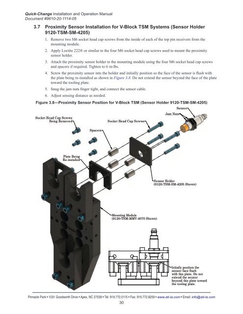
3.7 Proximity Sensor Installation for V-Block <strong>TSM</strong> Systems (Sensor Holder<br />
9120-<strong>TSM</strong>-SM-4205)<br />
1. Remove two M6 socket head cap screws from the inside of each of the top pin receivers from the<br />
mounting module.<br />
2. Apply Loctite 222® or similar to the four M6 socket head cap screws used to mount the proximity<br />
sensor holder.<br />
3. Attach the proximity sensor holder to the mounting module using the four M6 socket head cap screws<br />
and spacers if required. Tighten to 6 in-lbs.<br />
4. Screw the proximity sensor into the holder and initially position so the face of the sensor is flush with<br />
the plate being re-installed as shown in Figure 3.8. Do not extend the sensor beyond the face of the plate<br />
toward the tooling plate.<br />
5. Snug the jam nuts finger tight, and connect the sensor cable.<br />
6. Adjust sensing distance as needed.<br />
Figure 3.8—Proximity Sensor Position for V-Block <strong>TSM</strong> (Sensor Holder 9120-<strong>TSM</strong>-SM-4205)<br />
Sensor<br />
Jam Nuts<br />
Socket Head Cap Screws<br />
Being Removed<br />
Socket Head Cap Screws<br />
Spacers<br />
Plate Being<br />
Re-installed<br />
Sensor Holder<br />
(9120-<strong>TSM</strong>-SM-4205 Shown)<br />
Mounting Module<br />
(9120-<strong>TSM</strong>-MMV-4070 Shown)<br />
Initially position the<br />
sensor face flush<br />
with this plate. Do not<br />
extend the sensor<br />
beyond this plate toward<br />
the tooling plate.<br />
Pinnacle Park • 1031 Goodworth Drive • Apex, NC 27539 • Tel: 919.772.0115 • Fax: 919.772.8259 • www.ati-ia.com • Email: info@ati-ia.com<br />
30