TSM Tool Stand
TSM Tool Stand Manual - ATI Industrial Automation
TSM Tool Stand Manual - ATI Industrial Automation

Create successful ePaper yourself
Turn your PDF publications into a flip-book with our unique Google optimized e-Paper software.
Quick-Change Installation and Operation Manual<br />
Document #9610-20-1114-05<br />
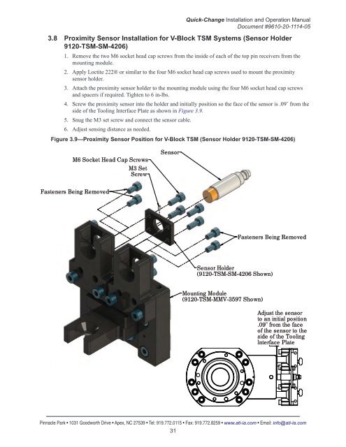
3.8 Proximity Sensor Installation for V-Block <strong>TSM</strong> Systems (Sensor Holder<br />
9120-<strong>TSM</strong>-SM-4206)<br />
1. Remove the two M6 socket head cap screws from the inside of each of the top pin receivers from the<br />
mounting module.<br />
2. Apply Loctite 222® or similar to the four M6 socket head cap screws used to mount the proximity<br />
sensor holder.<br />
3. Attach the proximity sensor holder to the mounting module using the four M6 socket head cap screws<br />
and spacers if required. Tighten to 6 in-lbs.<br />
4. Screw the proximity sensor into the holder and initially position so the face of the sensor is .09˝ from the<br />
side of the <strong>Tool</strong>ing Interface Plate as shown in Figure 3.9.<br />
5. Snug the M3 set screw and connect the sensor cable.<br />
6. Adjust sensing distance as needed.<br />
Figure 3.9—Proximity Sensor Position for V-Block <strong>TSM</strong> (Sensor Holder 9120-<strong>TSM</strong>-SM-4206)<br />
M6 Socket Head Cap Screws<br />
M3 Set<br />
Screw<br />
Sensor<br />
Fasteners Being Removed<br />
Fasteners Being Removed<br />
Sensor Holder<br />
(9120-<strong>TSM</strong>-SM-4206 Shown)<br />
Mounting Module<br />
(9120-<strong>TSM</strong>-MMV-3597 Shown)<br />
Adjust the sensor<br />
to an initial position<br />
.09" from the face<br />
of the sensor to the<br />
side of the <strong>Tool</strong>ing<br />
Interface Plate<br />
Pinnacle Park • 1031 Goodworth Drive • Apex, NC 27539 • Tel: 919.772.0115 • Fax: 919.772.8259 • www.ati-ia.com • Email: info@ati-ia.com<br />
31