TSM Tool Stand
TSM Tool Stand Manual - ATI Industrial Automation
TSM Tool Stand Manual - ATI Industrial Automation

You also want an ePaper? Increase the reach of your titles
YUMPU automatically turns print PDFs into web optimized ePapers that Google loves.
Quick-Change Installation and Operation Manual<br />
Document #9610-20-1114-05<br />
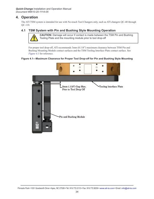
4. Operation<br />
The ATI <strong>TSM</strong> system is intended for use with No-touch <strong>Tool</strong> Changers only, such as ATI changers QC-40 through<br />
QC-110.<br />
4.1 <strong>TSM</strong> System with Pin and Bushing Style Mounting Operation<br />
CAUTION: Damage will occur if contact is made between the <strong>TSM</strong> Pin and Bushing<br />
<strong>Tool</strong>ing Plate and the mounting module prior to tool drop-off<br />
For proper tool drop-off, ATI recommends 3mm (0.118”) maximum clearance between <strong>TSM</strong> Pin and<br />
Bushing Mounting Module contact surfaces and the <strong>TSM</strong> <strong>Tool</strong>ing Interface Plate contact surface. See<br />
Figure 4.1 for reference.<br />
Figure 4.1—Maximum Clearance for Proper <strong>Tool</strong> Drop-off for Pin and Bushing Style Mounting<br />
3mm (.118”) Gap Max.<br />
Prior to <strong>Tool</strong> Drop Off<br />
<strong>Tool</strong>ing Interface Plate<br />
Pin and Bushing Module<br />
Pinnacle Park • 1031 Goodworth Drive • Apex, NC 27539 • Tel: 919.772.0115 • Fax: 919.772.8259 • www.ati-ia.com • Email: info@ati-ia.com<br />
34