


Create successful ePaper yourself
Turn your PDF publications into a flip-book with our unique Google optimized e-Paper software.
<strong>PI</strong> MI-LIGHT<br />
Tutorial<br />
This project is based on an original blog post by<br />
Torsten Tränkner that you will find in German here:<br />
torsten-traenkner.de. The project has only been<br />
tested on a Raspberry Pi 2, and may need some<br />
adaptation for other models of Pi.<br />
As you’ll see from the list of required components,<br />
this project does not involve any soldering. The<br />
RF module is connected to the Raspberry Pi using<br />
female-to-female jumper wires. Even though the<br />
Raspberry Pi will eventually take over the operation<br />
of the lights, you do need a Mi-Light remote control<br />
to set things up in the first place.<br />
Control your home<br />
lighting with a<br />
Raspberry Pi<br />
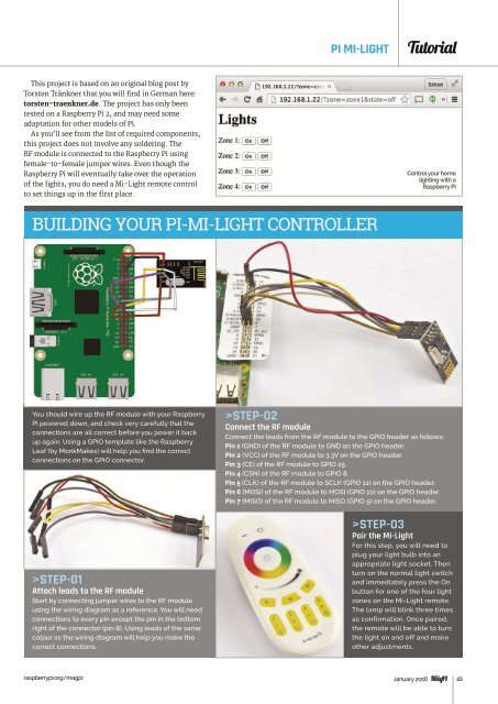
BUILDING <strong>YOUR</strong> <strong>PI</strong>-MI-LIGHT CONTROLLER<br />
You should wire up the RF module with your Raspberry<br />
Pi powered down, and check very carefully that the<br />
connections are all correct before you power it back<br />
up again. Using a G<strong>PI</strong>O template like the Raspberry<br />
Leaf (by MonkMakes) will help you find the correct<br />
connections on the G<strong>PI</strong>O connector.<br />
>STEP-01<br />
Attach leads to the RF module<br />
Start by connecting jumper wires to the RF module<br />
using the wiring diagram as a reference. You will need<br />
connections to every pin except the pin in the bottom<br />
right of the connector (pin 8). Using leads of the same<br />
colour as the wiring diagram will help you make the<br />
correct connections.<br />
>STEP-02<br />
Connect the RF module<br />
Connect the leads from the RF module to the G<strong>PI</strong>O header as follows:<br />
Pin 1 (GND) of the RF module to GND on the G<strong>PI</strong>O header.<br />
Pin 2 (VCC) of the RF module to 3.3V on the G<strong>PI</strong>O header.<br />
Pin 3 (CE) of the RF module to G<strong>PI</strong>O 25.<br />
Pin 4 (CSN) of the RF module to G<strong>PI</strong>O 8.<br />
Pin 5 (CLK) of the RF module to SCLK (G<strong>PI</strong>O 11) on the G<strong>PI</strong>O header.<br />
Pin 6 (MOSI) of the RF module to MOSI (G<strong>PI</strong>O 10) on the G<strong>PI</strong>O header.<br />
Pin 7 (MISO) of the RF module to MISO (G<strong>PI</strong>O 9) on the G<strong>PI</strong>O header.<br />
>STEP-03<br />
Pair the Mi-Light<br />
For this step, you will need to<br />
plug your light bulb into an<br />
appropriate light socket. Then<br />
turn on the normal light switch<br />
and immediately press the On<br />
button for one of the four light<br />
zones on the Mi-Light remote.<br />
The lamp will blink three times<br />
as confirmation. Once paired,<br />
the remote will be able to turn<br />
the light on and off and make<br />
other adjustments.<br />
raspberrypi.org/magpi January 2016 43