- Page 1 and 2: Imatest Documentation © 2009 Imate
- Page 3 and 4: Imatest Documentation Using SFRplus
- Page 5 and 6: Imatest Documentation Image Quality
- Page 7 and 8: Imatest Documentation tilted (about
- Page 9 and 10: Imatest Documentation MTF50 in Line
- Page 11 and 12: Imatest Documentation SQF Subjectiv
- Page 13 and 14: Imatest Documentation RAW converter
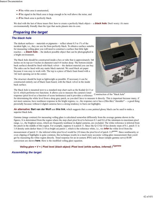
- Page 15 and 16: Imatest Documentation cm (4 inch) h
- Page 17 and 18: Imatest Documentation CSF( f ) = 2.
- Page 19 and 20: Imatest Documentation correlate wit
- Page 21 and 22: Imatest Documentation Unlike the ab
- Page 23 and 24: Imatest Documentation Since luminan
- Page 25 and 26: Imatest Documentation committee" (I
- Page 27 and 28: Imatest Documentation The formula f
- Page 29 and 30: Imatest Documentation The image to
- Page 31 and 32: Imatest Documentation Sharpness com
- Page 33 and 34: Imatest Documentation (DPR) Canon E
- Page 35 and 36: Imatest Documentation but their noi
- Page 37 and 38: Imatest Documentation The average t
- Page 39 and 40: Imatest Documentation Chromatic abe
- Page 41: Imatest Documentation Veiling glare
- Page 45 and 46: Imatest Documentation with UV filte
- Page 47 and 48: Imatest Documentation Czajkowski' r
- Page 49 and 50: Imatest Documentation P_Rm = O_Rm*A
- Page 51 and 52: Imatest Documentation Split view, s
- Page 53 and 54: Imatest Documentation ISO Sensitivi
- Page 55 and 56: Imatest Documentation Multicharts T
- Page 57 and 58: Imatest Documentation Shoulders are
- Page 59 and 60: Imatest Documentation Related docum
- Page 61 and 62: Imatest Documentation between image
- Page 63 and 64: Imatest Documentation We display va
- Page 65 and 66: Imatest Documentation Blur units, M
- Page 67 and 68: Imatest Documentation σ 2 = Σ (ti
- Page 69 and 70: Imatest Documentation Drill holes l
- Page 71 and 72: Imatest Documentation rummaging thr
- Page 73 and 74: Imatest Documentation Target size C
- Page 75 and 76: Imatest Documentation Level the tar
- Page 77 and 78: Imatest Documentation Kodak Q-14 St
- Page 79 and 80: Imatest Documentation Imatest Instr
- Page 81 and 82: Imatest Documentation in the Imates
- Page 83 and 84: Imatest Documentation samples (fold
- Page 85 and 86: Imatest Documentation Using Imatest
- Page 87 and 88: Imatest Documentation About RAW fil
- Page 89 and 90: Imatest Documentation Options I for
- Page 91 and 92: Imatest Documentation Special user
- Page 93 and 94:
Imatest Documentation CSV files- Ex
- Page 95 and 96:
Imatest Documentation RAW files RAW
- Page 97 and 98:
Imatest Documentation dcraw The ori
- Page 99 and 100:
Imatest Documentation The Rawview w
- Page 101 and 102:
Imatest Documentation identical (th
- Page 103 and 104:
Imatest Documentation The Imatest T
- Page 105 and 106:
Imatest Documentation Tripod and ac
- Page 107 and 108:
Imatest Documentation Targets Chart
- Page 109 and 110:
Imatest Documentation Left of cente
- Page 111 and 112:
Imatest Documentation Rope trick (f
- Page 113 and 114:
Imatest Documentation Distortion ta
- Page 115 and 116:
Imatest Documentation If you fail t
- Page 117 and 118:
Imatest Documentation Diagnostics r
- Page 119 and 120:
Imatest Documentation A horizontal
- Page 121 and 122:
Imatest Documentation the edges pri
- Page 123 and 124:
Imatest Documentation The camera mu
- Page 125 and 126:
Imatest Documentation Epson 2200 Pr
- Page 127 and 128:
Imatest Documentation Using SFR Par
- Page 129 and 130:
Imatest Documentation ROI fine adju
- Page 131 and 132:
Imatest Documentation Pixel size ha
- Page 133 and 134:
Imatest Documentation contrast in h
- Page 135 and 136:
Imatest Documentation Two precautio
- Page 137 and 138:
Imatest Documentation The PNG files
- Page 139 and 140:
Imatest Documentation nroi = 9 nwid
- Page 141 and 142:
Imatest Documentation An optional .
- Page 143 and 144:
Imatest Documentation SFR results:
- Page 145 and 146:
Imatest Documentation Right column
- Page 147 and 148:
Imatest Documentation Right: Input
- Page 149 and 150:
Imatest Documentation Below the plo
- Page 151 and 152:
Imatest Documentation Multi-ROI 2D
- Page 153 and 154:
Imatest Documentation The Legend at
- Page 155 and 156:
Imatest Documentation MTF50 (Cy/Pxl
- Page 157 and 158:
Imatest Documentation Summary plot
- Page 159 and 160:
Imatest Documentation 3D Plot for M
- Page 161 and 162:
Imatest Documentation The standard
- Page 163 and 164:
Imatest Documentation degrees are i
- Page 165 and 166:
Imatest Documentation Using SFRplus
- Page 167 and 168:
Imatest Documentation SFRplus setup
- Page 169 and 170:
Imatest Documentation SFRplus setti
- Page 171 and 172:
Imatest Documentation Gamma Gamma i
- Page 173 and 174:
Imatest Documentation Using SFRplus
- Page 175 and 176:
Imatest Documentation Weighted MTF5
- Page 177 and 178:
Imatest Documentation This display
- Page 179 and 180:
Imatest Documentation space of the
- Page 181 and 182:
Imatest Documentation window, shown
- Page 183 and 184:
Imatest Documentation It's easy to
- Page 185 and 186:
Imatest Documentation Using Reschar
- Page 187 and 188:
Imatest Documentation Select an ima
- Page 189 and 190:
Imatest Documentation MTF contours
- Page 191 and 192:
Imatest Documentation SFRplus SFR H
- Page 193 and 194:
Imatest Documentation Log F-Contras
- Page 195 and 196:
Imatest Documentation Log Frequency
- Page 197 and 198:
Imatest Documentation Color moiré
- Page 199 and 200:
Imatest Documentation The display o
- Page 201 and 202:
Imatest Documentation phase) is twi
- Page 203 and 204:
Imatest Documentation Downloadable
- Page 205 and 206:
Imatest Documentation If Express mo
- Page 207 and 208:
Imatest Documentation The display o
- Page 209 and 210:
Imatest Documentation The differenc
- Page 211 and 212:
Imatest Documentation Star Chart An
- Page 213 and 214:
Imatest Documentation ROI fine adju
- Page 215 and 216:
Imatest Documentation MTF (linear f
- Page 217 and 218:
Imatest Documentation The plot on t
- Page 219 and 220:
Imatest Documentation MTF Compare C
- Page 221 and 222:
Imatest Documentation MTF Compare r
- Page 223 and 224:
Imatest Documentation Comparison of
- Page 225 and 226:
Imatest Documentation Batchview Pos
- Page 227 and 228:
Imatest Documentation Rescharts SFR
- Page 229 and 230:
Imatest Documentation Running Batch
- Page 231 and 232:
Imatest Documentation Center mean O
- Page 233 and 234:
Imatest Documentation standard mono
- Page 235 and 236:
Imatest Documentation Lighting Inte
- Page 237 and 238:
Imatest Documentation Run Imatest S
- Page 239 and 240:
Imatest Documentation SFRplus setup
- Page 241 and 242:
Imatest Documentation SFRplus setti
- Page 243 and 244:
Imatest Documentation Additional pa
- Page 245 and 246:
Imatest Documentation Output files
- Page 247 and 248:
Imatest Documentation Lens-style MT
- Page 249 and 250:
Imatest Documentation File formats
- Page 251 and 252:
Imatest Documentation Purchase or d
- Page 253 and 254:
Imatest Documentation Sharpness tar
- Page 255 and 256:
Imatest Documentation Proper exposu
- Page 257 and 258:
Imatest Documentation If you answer
- Page 259 and 260:
Imatest Documentation SFR input dia
- Page 261 and 262:
Imatest Documentation Figures (.PNG
- Page 263 and 264:
Imatest Documentation contrast imag
- Page 265 and 266:
Imatest Documentation Chromatic Abe
- Page 267 and 268:
Imatest Documentation QA-61 ISO-160
- Page 269 and 270:
Imatest Documentation Stepchart inp
- Page 271 and 272:
Imatest Documentation First Figure:
- Page 273 and 274:
Imatest Documentation Third Figure:
- Page 275 and 276:
Imatest Documentation A camera's (o
- Page 277 and 278:
Imatest Documentation The total dyn
- Page 279 and 280:
Imatest Documentation Gamc is typic
- Page 281 and 282:
Imatest Documentation ISO-15739 Noi
- Page 283 and 284:
Imatest Documentation You can enter
- Page 285 and 286:
Imatest Documentation Results If RA
- Page 287 and 288:
Imatest Documentation Dynamic range
- Page 289 and 290:
Imatest Documentation Using Colorch
- Page 291 and 292:
Imatest Documentation horizontal fi
- Page 293 and 294:
Imatest Documentation Colorcheck in
- Page 295 and 296:
Imatest Documentation The first fig
- Page 297 and 298:
Imatest Documentation The backgroun
- Page 299 and 300:
Imatest Documentation saturated gre
- Page 301 and 302:
Imatest Documentation (blank line)
- Page 303 and 304:
Imatest Documentation CMC An early
- Page 305 and 306:
Imatest Documentation The the equat
- Page 307 and 308:
Imatest Documentation Multicharts o
- Page 309 and 310:
Imatest Documentation If you select
- Page 311 and 312:
Imatest Documentation The Zoom chec
- Page 313 and 314:
Imatest Documentation + b* Pseudoco
- Page 315 and 316:
Imatest Documentation Shows the gra
- Page 317 and 318:
Imatest Documentation Multicharts S
- Page 319 and 320:
Imatest Documentation Read from a 5
- Page 321 and 322:
Imatest Documentation Use these ord
- Page 323 and 324:
Imatest Documentation Color correct
- Page 325 and 326:
Imatest Documentation Options: Colo
- Page 327 and 328:
Imatest Documentation Exif and Colo
- Page 329 and 330:
Imatest Documentation The Labsphere
- Page 331 and 332:
Imatest Documentation Scaling butto
- Page 333 and 334:
Imatest Documentation F-stop contou
- Page 335 and 336:
Imatest Documentation Uniformity (L
- Page 337 and 338:
Imatest Documentation density— vi
- Page 339 and 340:
Imatest Documentation the Corner an
- Page 341 and 342:
Imatest Documentation The local noi
- Page 343 and 344:
Imatest Documentation Local nonunif
- Page 345 and 346:
Imatest Documentation Image with sp
- Page 347 and 348:
Imatest Documentation Using Distort
- Page 349 and 350:
Imatest Documentation Set exposure
- Page 351 and 352:
Imatest Documentation Plot distorti
- Page 353 and 354:
Imatest Documentation Imatest will
- Page 355 and 356:
Imatest Documentation MTF (sharpnes
- Page 357 and 358:
Imatest Documentation Intersection
- Page 359 and 360:
Imatest Documentation function of r
- Page 361 and 362:
Imatest Documentation Imatest Instr
- Page 363 and 364:
Imatest Documentation Horizontal di
- Page 365 and 366:
Imatest Documentation Zone plates (
- Page 367 and 368:
Imatest Documentation Along with ch
- Page 369 and 370:
Imatest Documentation Preview image
- Page 371 and 372:
Imatest Documentation Light Falloff
- Page 373 and 374:
Imatest Documentation Monitor Calib
- Page 375 and 376:
Imatest Documentation Black level (
- Page 377 and 378:
Imatest Documentation Reset pattern
- Page 379 and 380:
Imatest Documentation SVG Test Char
- Page 381 and 382:
Imatest Documentation SVG SFR chart
- Page 383 and 384:
Imatest Documentation To run Test C
- Page 385 and 386:
Imatest Documentation Invert light/
- Page 387 and 388:
Imatest Documentation Contrast (alt
- Page 389 and 390:
Imatest Documentation window. Print
- Page 391 and 392:
Imatest Documentation files. Quick
- Page 393 and 394:
Imatest Documentation File selectio
- Page 395 and 396:
Imatest Documentation Imatest IT/EX
- Page 397 and 398:
Imatest Documentation cyclesper_val
- Page 399 and 400:
Imatest Documentation optional. The
- Page 401 and 402:
Imatest Documentation Change to the
- Page 403 and 404:
Imatest Documentation Detailed inst
- Page 405 and 406:
Imatest Documentation Scanner profi
- Page 407 and 408:
Imatest Documentation Although this
- Page 409 and 410:
Imatest Documentation Gamut is exce
- Page 411 and 412:
Imatest Documentation S=1 HSL Hue p
- Page 413 and 414:
Imatest Documentation An additional
- Page 415 and 416:
Imatest Documentation Instructions
- Page 417 and 418:
Imatest Documentation 7. 8. Mask im
- Page 419 and 420:
Imatest Documentation 9. Corr Image
- Page 421 and 422:
Imatest Documentation Appendix Cros
- Page 423 and 424:
Imatest Documentation Sorted by tes
- Page 425 and 426:
Imatest Documentation Distortion Un
- Page 427 and 428:
Imatest Documentation Create Scalab
- Page 429 and 430:
Imatest Documentation f-stop . Gamm
- Page 431 and 432:
Imatest Documentation Glosario en E
- Page 433 and 434:
Imatest Documentation Troubleshooti
- Page 435 and 436:
Imatest Documentation You can selec
- Page 437 and 438:
Imatest Documentation Imatest Chang
- Page 439 and 440:
Imatest Documentation below, next t
- Page 441 and 442:
Imatest Documentation Jan. 6, 2007
- Page 443 and 444:
Imatest Documentation Nov. 6, 2005
- Page 445 and 446:
Imatest Documentation Sept. 11, 200
- Page 447 and 448:
Imatest Documentation XML Changes N
- Page 449 and 450:
Imatest Documentation License The I
- Page 451:
Imatest Documentation 11. GENERAL T