FVA/A1 STERILIZERS
FVA/A1 STERILIZERS
FVA/A1 STERILIZERS

You also want an ePaper? Increase the reach of your titles
YUMPU automatically turns print PDFs into web optimized ePapers that Google loves.
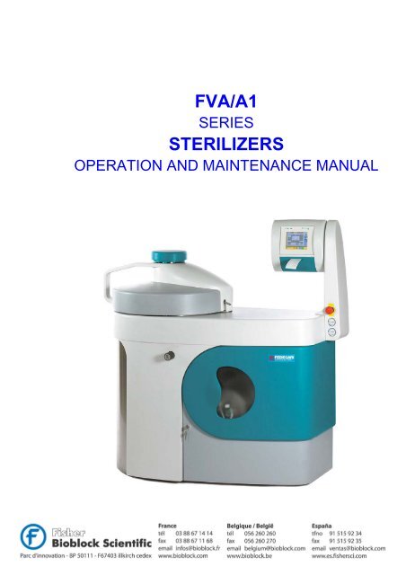
<strong>FVA</strong>/<strong>A1</strong><br />
SERIES<br />
<strong>STERILIZERS</strong><br />
OPERATION AND MAINTENANCE MANUAL<br />
FEDEGARI AUTOKLAVEN AG<br />
� Via alla Gerra, 11 • CH-6930 Bedano - SWITZERLAND<br />
� 0041 91 9352090 • � 0041 91 9352099 • � http://www.fedegariautoklaven.ch
6. Process controller<br />
with integrated<br />
operator panel (Touch<br />
screen)<br />
7. Vacuum gauges for<br />
chamber and<br />
generator monitoring<br />
8. Emergency<br />
pushbutton<br />
9. Process printer<br />
10. Main switch<br />
11. Castors<br />
<strong>FVA</strong>/<strong>A1</strong> - OPERATION AND<br />
MAINTENANCE MANUAL<br />
1. Sterilizer<br />
2. Technical area cabinet<br />
3. Manual discharge valve<br />
4. Safety lever of lid closure system<br />
5. Handle for opening sterilization<br />
chamber lid<br />
12. Load lifting device (hoist)<br />
13. Fastening accessory<br />
14. Product loading/unloading devices<br />
15. Chamber lid in fully open position<br />
! WARNING!<br />
FOR COMPLETE AND EXHAUSTIVE INFORMATION REGARDING THE<br />
OPERATION AND MAINTENANCE OF THIS MACHINE,<br />
PLEASE REFER TO THE TECHNICAL MANUAL<br />
July 2005 ID no. 85693 Rev. 2
<strong>FVA</strong>/<strong>A1</strong> - OPERATION AND<br />
MAINTENANCE MANUAL<br />
CONTENTS<br />
1. INTRODUCTION ................................................................................................................................................... 4<br />
1.1. PURPOSE OF THIS DOCUMENT.................................................................................................................... 4<br />
1.1.1. DOCUMENT IDENTIFICATION ..........................................................................................................................................4<br />
1.2. DISCLAIMERS.................................................................................................................................................. 4<br />
1.3. CONFIDENTIALITY .......................................................................................................................................... 4<br />
1.4. ASSOCIATED DOCUMENTS ........................................................................................................................... 4<br />
1.5. USING THIS MANUAL...................................................................................................................................... 4<br />
1.6. MAINTAINING THE MANUAL........................................................................................................................... 4<br />
1.7. UPDATES ......................................................................................................................................................... 5<br />
1.8. ALARM SYMBOLS............................................................................................................................................ 5<br />
1.9. REFERENCES TO STANDARDS..................................................................................................................... 5<br />
2. SAFETY IN OPERATION ...................................................................................................................................... 6<br />
2.1. INTENDED USE................................................................................................................................................ 6<br />
2.2. PROHIBITED USE............................................................................................................................................ 6<br />
2.3. GENERAL POTENTIAL DANGERS.................................................................................................................. 7<br />
2.4. RISKS LINKED TO USE OF THE SOFTWARE................................................................................................ 8<br />
2.5. OPERATOR QUALIFICATION.......................................................................................................................... 8<br />
2.6. PERSONAL PROTECTION MEANS................................................................................................................. 9<br />
2.7. RECOMMENDATIONS AND PREVENTIVE STEPS TO BE TAKEN BY THE USER....................................... 9<br />
2.8. EMERGENCY SITUATIONS............................................................................................................................. 9<br />
2.8.1. BLACKOUT - ELECTRICAL SYSTEM ................................................................................................................................9<br />
2.8.2. FAILURE OF WATER SUPPLY ........................................................................................................................................10<br />
2.8.3. SHUTDOWN......................................................................................................................................................................10<br />
2.8.4. EMERGENCY STOP.........................................................................................................................................................10<br />
3. GENERAL DESCRIPTION OF THE MACHINE .................................................................................................. 11<br />
3.1. iNTRODUCTION............................................................................................................................................. 11<br />
3.2. RANGE IDENTIFICATION .............................................................................................................................. 11<br />
3.3. MACHINE IDENTIFICATION .......................................................................................................................... 11<br />
3.4. KEY COMPONENTS OF THE MACHINE....................................................................................................... 12<br />
3.5. MAIN ADDITIONAL (OPTIONAL) COMPONENTS OF THE MACHINE ......................................................... 12<br />
3.6. CONTROL AND MONITORING DEVICES ..................................................................................................... 12<br />
July 2005 1 / 31 ID no. 85693 Rev. 2
<strong>FVA</strong>/<strong>A1</strong> - OPERATION AND<br />
MAINTENANCE MANUAL<br />
3.6.1. CONTROL AND MONITORING STATIONS .................................................................................................................... 13<br />
3.7. SAFETY SYSTEMS ........................................................................................................................................ 13<br />
3.7.1. DESCRIPTION OF THE CHAMBER CLOSING AND OPENING SYSTEM ..................................................................... 13<br />
3.7.2. SAFETY VALVES ............................................................................................................................................................. 14<br />
3.8. TECHNICAL DATA ......................................................................................................................................... 14<br />
3.8.1. MAIN DIMENSIONS AND WEIGHTS............................................................................................................................... 14<br />
3.8.2. TECHNICAL PARAMETERS............................................................................................................................................ 14<br />
3.8.3. WATER/AIR CONSUMPTION .......................................................................................................................................... 15<br />
3.8.4. EMC SPECIFICATIONS ................................................................................................................................................... 15<br />
4. TRANSPORT, HANDLING AND STORAGE ...................................................................................................... 16<br />
4.1. TRANSPORT.................................................................................................................................................. 16<br />
4.2. HANDLING...................................................................................................................................................... 16<br />
4.3. STORAGE....................................................................................................................................................... 16<br />
5. INSTALLATION................................................................................................................................................... 17<br />
5.1. ACCEPTABLE ENVIRONMENTAL CONDITIONS FOR OPERATION........................................................... 17<br />
5.2. REMOVING PROTECTIVE MATERIALS ....................................................................................................... 17<br />
5.3. MACHINE PLACEMENT................................................................................................................................. 17<br />
5.4. CONNECTION TO POWER SOURCES AND UTILITIES............................................................................... 17<br />
5.4.1. HYDRAULIC CONNECTIONS.......................................................................................................................................... 18<br />
5.4.2. CONNECTIONS TO THE ELECTRIC POWER SUPPLY................................................................................................. 18<br />
5.5. CHECKING THE INSTALLATION................................................................................................................... 18<br />
6. USE ..................................................................................................................................................................... 19<br />
6.1. GENERAL DESCRIPTION OF OPERATION.................................................................................................. 19<br />
6.2. SOFTWARE STRUCTURE............................................................................................................................. 19<br />
6.3. ACCESS LEVELS........................................................................................................................................... 20<br />
6.4. OPERATING PHASES ................................................................................................................................... 20<br />
6.4.1. INITIAL TESTS ................................................................................................................................................................. 20<br />
6.4.2. POWER-ON...................................................................................................................................................................... 21<br />
6.4.3. PRODUCT LOADING ....................................................................................................................................................... 22<br />
6.4.4. PROGRAM START AND RUN ......................................................................................................................................... 24<br />
6.4.5. PRODUCT UNLOADING.................................................................................................................................................. 24<br />
6.4.6. SHUTDOWN..................................................................................................................................................................... 25<br />
6.5. “PHASE STEP” AND “CYCLE STOP” FUNCTIONS....................................................................................... 25<br />
6.6. ALARM MESSAGES...................................................................................................................................... 26<br />
6.7. EMERGENCY PHASE.................................................................................................................................... 26<br />
ID no. 85693 Rev. 2 2 / 31 July 2005
<strong>FVA</strong>/<strong>A1</strong> - OPERATION AND<br />
MAINTENANCE MANUAL<br />
6.8. AUXILIARY FUNCTIONS................................................................................................................................ 26<br />
7. ALARMS AND TROUBLESHOOTING................................................................................................................ 27<br />
7.1. ALARMS ......................................................................................................................................................... 27<br />
8. ORDINARY MAINTENANCE .............................................................................................................................. 28<br />
8.1. PREVENTIVE MAINTENANCE PROCEDURES ............................................................................................ 28<br />
8.1.1. VISUAL INSPECTION.......................................................................................................................................................28<br />
8.1.2. CLEANING ........................................................................................................................................................................28<br />
8.1.3. PERIODIC EFFICIENCY CHECKS...................................................................................................................................29<br />
8.2. CORRECTIVE MAINTENANCE PROCEDURES............................................................................................ 29<br />
8.2.1. REMOVING JAMS.............................................................................................................................................................29<br />
9. REMOVAL FROM SERVICE............................................................................................................................... 30<br />
10. TECHNICAL SUPPORT ...................................................................................................................................... 31<br />
July 2005 3 / 31 ID no. 85693 Rev. 2
1. INTRODUCTION<br />
<strong>FVA</strong>/<strong>A1</strong> - OPERATION AND<br />
MAINTENANCE MANUAL<br />
1.1. PURPOSE OF THIS DOCUMENT<br />
This manual is intended for users of sterilizers of the <strong>FVA</strong>/<strong>A1</strong> range. It contains all the information required for proper use of these<br />
machines. Strict and sensible compliance with the instructions and rules given in this manual is essential for the proper operation and<br />
durability of each machine and for safeguarding and protecting the safety of the operator and of the materials being processed.<br />
Accordingly, you should read carefully all the prescriptions given in this manual and follow them strictly. All the information given here<br />
is up-to-date as of the publication date.<br />
1.1.1. DOCUMENT IDENTIFICATION<br />
This “OPERATION AND MAINTENANCE MANUAL” is an official document issued by FEDEGARI AUTOKLAVEN AG (hereafter<br />
referenced as FEDEGARI for the sake of brevity) and is an integral part of the machine. It is identified by a Document Code given in<br />
the footer of each page, allowing its identification, traceability and subsequent reference.<br />
1.2. DISCLAIMERS<br />
FEDEGARI has made every effort to ensure that the information contained in this manual is accurate and exhaustive. However, it<br />
assumes no responsibility in case of errors or omissions. FEDEGARI reserves itself the right to amend, at any time and without<br />
notice, the specifications of the hardware and software described in this document. FEDEGARI reserves itself the option of amending<br />
this manual at any time without notice.<br />
1.3. CONFIDENTIALITY<br />
Full or partial duplication, transmission, transcription or storage in an information retrieval system, and translation into other<br />
languages, in any form, of this manual and of the associated documents are strictly prohibited without the prior written permission of<br />
FEDEGARI.<br />
1.4. ASSOCIATED DOCUMENTS<br />
Further information on this sterilizer is available in the following document:<br />
� TECHNICAL MANUAL<br />
1.5. USING THIS MANUAL<br />
This manual must be read sequentially, i.e., from beginning to end, one page after the other, and the various notices and WARNING!s<br />
must be understood and remembered.<br />
Since it is assumed that the operator is qualified to use this type of machine, all general information and instructions that necessarily<br />
must be part of his background knowledge have been omitted.<br />
This manual must be considered as an integral part of the machine and must therefore follow it in all its transfers, both within and<br />
outside the company in which it is used.<br />
1.6. MAINTAINING THE MANUAL<br />
This manual must be preserved throughout the life of the machine. Store this manual in places that are protected against humidity<br />
and heat. Do not remove, tear or rewrite parts of this manual for any reason.<br />
If operating situations that are not considered by, or do not match, the ones presented in this manual occur, contact the manufacturer<br />
immediately for a possible update.<br />
You must ensure that all the updates you receive promptly replace the corresponding obsolete documents.<br />
This manual must be stored with the greatest possible care. Avoid inappropriate handling and any damage, however partial, to its<br />
contents.<br />
The operator is responsible for replacing the manual immediately if it is damaged, lost or rendered fully or partially unintelligible.<br />
ID no. 85693 Rev. 2 4 / 31 July 2005
<strong>FVA</strong>/<strong>A1</strong> - OPERATION AND<br />
MAINTENANCE MANUAL<br />
1.7. UPDATES<br />
Any updates to this document will be sent to the owner of the machine in electronic format together with suitable instructions for<br />
viewing them.<br />
If the machine is to change owner, the current owner should report to FEDEGARI the appropriate information in order to allow any<br />
updates to be sent to the new owner.<br />
1.8. ALARM SYMBOLS<br />
In this manual, the following symbols inform the user of the availability of additional information not contained in the text, of<br />
particularly important information, and of particularly delicate and dangerous procedures.<br />
� NOTE<br />
This symbol indicates important information highlighted separately from the text.<br />
; CAUTION<br />
This symbol indicates a condition in which negligence or incorrectly performed procedures can cause possibly<br />
irreparable damage to the sterilizer.<br />
! WARNING!<br />
This symbol is used to indicate a situation that entails danger to people.<br />
For certain specific risks, these generic symbols are complemented by particular symbols that are explained in each instance in the<br />
text.<br />
These additional symbols match the ones provided on the machine by means of plates and/or stickers to indicate dangerous areas<br />
and behaviors.<br />
Before approaching the machine and starting any operation, whether for normal use or for maintenance, you must read carefully<br />
these signs, messages and instructions and understand their meaning.<br />
The operator is responsible for immediately replacing any plates, stickers, panels etc. applied to the machine that have been lost or<br />
damaged or have become partly or fully unintelligible.<br />
1.9. REFERENCES TO STANDARDS<br />
The contents of this document comply with the requirements of the following standards:<br />
- UNI EN 292/2 - 1992 ISO 292/2;<br />
- EN 61010-1 - 2001 IEC 1010-1;<br />
- EN 61010-2-041 - 1997 IEC 1010-2-041;<br />
and with the following European Directives:<br />
MD 98/37/EC (Machinery Directive);<br />
LVD 73/23/EC (Electrical Safety) and subsequent amendments thereof;<br />
PED 97/23/EC (Pressure Equipment);<br />
MDD 93/42/EC (Medical devices 1 );<br />
EMC 89/336/EC (Electromagnetic Compatibility) and subsequent amendments thereof.<br />
1 Sterilizers used to treat medical devices before reuse must comply with directive 93/42/EC and with the EN285 standard. To meet<br />
fully these requirements, the Independent data logging option and the Vacuum pump option must be included in the supply;<br />
furthermore, the installation tests must be performed as required by the EN 285 standard.<br />
July 2005 5 / 31 ID no. 85693 Rev. 2
2. SAFETY IN OPERATION<br />
2.1. INTENDED USE<br />
! WARNING!<br />
<strong>FVA</strong>/<strong>A1</strong> - OPERATION AND<br />
MAINTENANCE MANUAL<br />
It is absolutely forbidden to use the sterilizer and its accessories for any use other than the allowed use specified in<br />
this manual.<br />
Depending on the chosen configuration, these sterilizers are capable of sterilizing solids and liquids by using various sterilization<br />
processes. In its basic configuration, the machine is suitable to process the following products.<br />
Sterilization of solids:<br />
- empty laboratory glassware;<br />
- stainless steel instruments, in bags or loose;<br />
- machine parts;<br />
- small stainless steel containers;<br />
- miscellaneous laboratory material;<br />
- delicate membranes and filters;<br />
- solid laboratory waste in open bags or contaminated liquids (materials that can cause microbiological contamination on<br />
the part of viruses or bacteria of the surrounding environment).<br />
Sterilization of liquids:<br />
- liquids and culture media (agar) contained in non-hermetically closed containers;<br />
- various solutions contained in non-hermetically closed containers;<br />
- various solutions contained in small hermetically-closed containers.<br />
2.2. PROHIBITED USE<br />
! WARNING!<br />
All uses that are not specified explicitly in the previous subsection must be assumed to be prohibited.<br />
It is necessary to avoid treating the following materials:<br />
- flammable or explosive substances;<br />
- non-flammable liquids that have a high vapor pressure (halocarbons and the like), even in closed containers;<br />
- gas in bottles and spray cans (even if the cans are depleted because they have been used up);<br />
- substances that due to decomposition caused by moist heat can generate toxic, noxious, flammable, or<br />
explosive gases or vapors or can generate flammable, noxious, toxic solids or residues.<br />
! WARNING!<br />
Moreover, since the sterilizing effect is ensured by the direct or indirect contact of water vapour with the surfaces to be<br />
treated, moist-heat sterilization processes are accordingly not suitable for treating:<br />
- closed vapor-impermeable containers whose interior is to be sterilized (for example closed empty ampoules);<br />
- closed vapor-impermeable containers containing an anhydrous material to be sterilized (for example ampoules<br />
containing anhydrous oily substances and anhydrous powders).<br />
When in doubt, it is advisable in any case to consult FEDEGARI beforehand.<br />
ID no. 85693 Rev. 2 6 / 31 July 2005
<strong>FVA</strong>/<strong>A1</strong> - OPERATION AND<br />
MAINTENANCE MANUAL<br />
2.3. GENERAL POTENTIAL DANGERS<br />
! WARNING!<br />
Most workplace accidents arise from failure to observe the most elementary safety rules. Anyone working on the<br />
machine must know perfectly the rules given in this document and on the WARNING! plates and comply with them. It<br />
is strictly necessary to comply with the general rules given hereafter.<br />
The input terminals of the power supply line are live even when the main switch is disengaged (“OFF” position).<br />
It is absolutely forbidden to disable for any reason the safeties installed on the machine.<br />
Only personnel of the manufacturer FEDEGARI, or, following authorization by FEDEGARI, qualified personnel of the<br />
user can perform reduced-safety operations.<br />
Before proceeding to use the sterilizer, ALWAYS check that the materials to be processed are compatible with the<br />
cycles and steps provided by the sterilization program that you intend to start. Check in particular that the materials<br />
do not have an inherent risk of molecular instability that may cause explosions as a consequence of handling or<br />
processing.<br />
Do not carry out work or modifications of any kind on the machine or on its accessories. Do not modify in any way<br />
and for any reason parts of the sterilizer in order to adapt additional devices or other items to them. In case of<br />
malfunction/accident due to failure to comply with this prescription, FEDEGARI is not responsible for the<br />
consequences.<br />
You should contact FEDEGARI in case of requirements regarding modifications to be made to machine.<br />
If the machine is equipped with the optional kit (Safety thermal locking device), ALWAYS position accurately, and as<br />
specified hereafter, the heat probe, which also acts as a safety for the chamber opening temperature.<br />
Always pay great attention to the temperature indication on the display, because:<br />
� when placing the heat probe among the bottles (not inside them) of one of the lowest layers of the load, the<br />
heat probe is able to detect the temperature of the sterilization chamber, and therefore it is NECESSARY to<br />
take into account the delay with which the liquid inside the bottles reaches the temperature displayed by the<br />
heat probe. This delay is directly proportional to the volume of the bottles.<br />
For 50-cc bottles, it is NECESSARY to consider a safety margin of at least 30°C (for bottles having a larger<br />
volume, this margin must be greater), and therefore the chamber must be cooled to a temperature of at least<br />
40°C in order to admit that the internal temperature of the bottles is not higher than 70°C, which is the<br />
normally acceptable value.<br />
� When placing the heat probe inside a bottle immersed in the liquid contained by the bottle, it is not necessary<br />
to consider safety margins, but there is still the risk that the reference bottle might break during the process<br />
and that therefore the indication of the heat probe again refers to the chamber rather than to the inside of the<br />
bottle.<br />
Before starting a sterilization cycle, absolutely always check that the manual discharge valve is perfectly closed.<br />
Fire-fighting means of the CO2 type are recommended for fire prevention.<br />
It is absolutely forbidden to use the sterilizer and its accessories for any use other than the use allowed and<br />
specified in this manual.<br />
These sterilizers are not electromedical devices.<br />
Any installation of these machines in the vicinity of areas containing electromedical devices must be assessed as<br />
regards the maximum levels of electromagnetic interference tolerance of such devices.<br />
If electromedical devices characterized by low immunity to interference are present, it is advisable to connect the<br />
power supply lines of these devices and of the sterilizer on separate circuits.<br />
FEDEGARI autoclaves have been subjected to measurements in order to determine the maximum level of<br />
electromagnetic noise emitted by conduction and the level of immunity to interference from a typical installation<br />
environment. The results are given in the “EMC SPECIFICATIONS” subsection and comply with the required<br />
standards currently in force for industrial and civil environments.<br />
! WARNING!<br />
Suitable WARNING! plates are placed onboard the machine to indicate potential dangers. The symbols used comply<br />
with European standards.<br />
July 2005 7 / 31 ID no. 85693 Rev. 2
Symbol/Description of plate Plate location<br />
; CAUTION<br />
It is absolutely indispensable to ensure the following:<br />
1. Main switch<br />
2. Manual valve for discharging chamber pressure<br />
1. Inside the technical area panel<br />
2. Rear of electrical panel<br />
1. Chamber body<br />
2. Steam generator<br />
1. Electrical panel<br />
<strong>FVA</strong>/<strong>A1</strong> - OPERATION AND<br />
MAINTENANCE MANUAL<br />
the stability of the power supply voltage intended for the sterilizer must be within a tolerance equal to ± 10% of the<br />
required nominal value (frequency ± 2%);<br />
failure to comply with this recommendation may cause severe malfunctions during sterilization cycles and damage<br />
to the machine;<br />
while cleaning or washing the chamber or parts of the sterilizer, absolutely do not use alcohol, gasoline, solvents of<br />
any kind or substances that have an acid reaction, which can damage the stainless steel surfaces and the elastomer<br />
parts;<br />
use water, optionally in a weak solution with neutral detergents, in the manner described in the maintenance<br />
instructions given in this manual;<br />
in any kind of process, and particularly during manual interventions, FEDEGARI guarantees the sterilization<br />
processes of its machines only when the person in charge of the process has given clearance of correct execution of<br />
all the phases of the cycle provided for the product, by placing an approval signature on the document printed by the<br />
control system of the autoclave.<br />
2.4. RISKS LINKED TO USE OF THE SOFTWARE<br />
Use of the software provided by FEDEGARI together with its products is granted under license and occurs under the full responsibility<br />
of the customer (see also the General Terms of Sale).<br />
! WARNING!<br />
FEDEGARI or its representatives cannot in any circumstance be deemed responsible for direct or indirect damage<br />
arising from the use of the software, from any defects present in the software, or otherwise arising from the users’<br />
license of the software.<br />
2.5. OPERATOR QUALIFICATION<br />
The operations described in this manual and related to the individual phases of the life cycle of the machine have been analyzed<br />
carefully and exhaustively by FEDEGARI also in accordance with the characteristics of the operator.<br />
Operator competence is a necessary and indispensable condition to allow correct use of the machine in compliance with all the safety<br />
requirements of this manual.<br />
ID no. 85693 Rev. 2 8 / 31 July 2005
<strong>FVA</strong>/<strong>A1</strong> - OPERATION AND<br />
MAINTENANCE MANUAL<br />
2.6. PERSONAL PROTECTION MEANS<br />
The assigned operator, in accordance with the nature of the loads to be treated, must be able to protect his body by using adequate<br />
protective means.<br />
! WARNING!<br />
Before taking charge of the load, the operator must ALWAYS be able to check and ascertain the nature of the<br />
materials that constitute it.<br />
The assigned operator must work with clothing that offers adequate protection against the potential risks caused by<br />
contact with the most disparate materials.<br />
It is the responsibility of the buyer to ensure, in compliance with the standards applicable in the country where the<br />
machine is used, that the means used have the highest degree of protection in relation to the type of product to be<br />
processed.<br />
The protective means to be adopted must allow sufficient freedom of motion to perform the intended manoeuvers.<br />
As regards visual perception, such means must preserve the broadest angle with the lowest distortion.<br />
Use only certified and approved protective means. The protective means must be used and maintained correctly<br />
(e.g., worn correctly, fastenings closed appropriately, mask filters replaced, et cetera).<br />
; CAUTION<br />
Personal protection means are expressly recommended for certain cases in order to protect the processed product,<br />
so as to avoid its contamination (typically during unloading operations).<br />
In any case, when dealing with products that entail no chemical or microbiological risk, it is advisable:<br />
- to wear an impermeable cotton overall or other clothing that allows good breathability but does not leave any part of the body<br />
exposed except for the face;<br />
- to wear shoes that offer an adequate degree of comfort as well as suitable mechanical protection and good insulation against any<br />
spillage of liquids;<br />
- to wear spray protection goggles that have a lightweight structure, are not made of glass or splintering materials, and are<br />
transparent, with the best refractive index, the best visual angle and the lowest degree of distortion.<br />
2.7. RECOMMENDATIONS AND PREVENTIVE STEPS TO BE TAKEN BY THE USER<br />
It is the user’s responsibility to provide the installation area with lighting systems that are suitable and approved by applicable<br />
workplace health and safety standards.<br />
The user must ensure that the work area in front of the sterilizer has non-slip flooring. This flooring must be made of inert or polymeric<br />
materials that are easily washable and resistant to chemical and thermal disinfection treatments. The flooring must be resistant to any<br />
intended sanitization treatments in accordance with the products to be sterilized.<br />
Clear and legible graphic signs forbidding access of unauthorized personnel to the work area must be placed conspicuously in the<br />
vicinity of the work area.<br />
Before tasks are assigned, the user must train the assigned operators appropriately and ensure that they have acquired the<br />
necessary knowledge and manual skills according to the required profile of professional characteristics.<br />
It is the user’s responsibility to provide the machine installation area with suitable firefighting stations. The operator must be able to<br />
access, in case of emergency, the main switch and the flow control valves of the primary supplies.<br />
! WARNING!<br />
Firefighting means of the CO2 type are recommended for fire prevention.<br />
2.8. EMERGENCY SITUATIONS<br />
The machine must always be safe, even during abnormal conditions and after such conditions cease.<br />
2.8.1. BLACKOUT - ELECTRICAL SYSTEM<br />
If an electrical “blackout” occurs, the sterilizer shuts down.<br />
If the sterilizer was in a phase of an operating cycle:<br />
July 2005 9 / 31 ID no. 85693 Rev. 2
<strong>FVA</strong>/<strong>A1</strong> - OPERATION AND<br />
MAINTENANCE MANUAL<br />
When electric power returns, an acoustic alarm is issued and the operator must recognize the emergency state by acting<br />
on the mute icon of the touch-screen;<br />
The operator must then leave the emergency state by acting on the STOP icon of the touch-screen;<br />
The sterilizer is thus brought to the atmospheric pressure balancing phase.<br />
If the sterilizer was not in a phase of an operating cycle:<br />
when electric power returns, the Fedegari logo is displayed while waiting for commands from the operator.<br />
The sterilization chamber is provided with a pneumatic gasket for sealing the lid and with associated devices for ensuring the<br />
tightness of the chamber even if there is no electric or pneumatic power.<br />
In particular, depressurization of the pneumatic gasket of the door takes longer than the depressurization of the chamber.<br />
Atmospheric pressure in the chamber, caused by failure of the tightness of the gasket as a consequence of a blackout, is reached<br />
after at least 20 hours, depending on the overall maintenance level of the machine.<br />
2.8.2. FAILURE OF WATER SUPPLY<br />
In order to ensure that the steam generator is supplied with pressurized water at 1 to 4 bars, the sterilizer is provided with a selfpriming<br />
pump, which is capable of drawing water from any container located outside the sterilizer or from the water supply mains.<br />
In order to protect its integrity, the self-priming pump is equipped with a suitable internal device for checking the minimum level of the<br />
liquid.<br />
Any interruption in the water supply of the steam generator increases the time required to complete the process phases in progress. If<br />
the water supply fails, the sterilizer issues an acoustic alarm signal and is then forced by the operator into a state known as<br />
“emergency” and waits for the optimum parameters to be stored.<br />
� NOTE<br />
If the optional Vacuum and drying assembly kit or the Quick drying assembly kit is installed, the sterilizer is<br />
equipped with a vacuum pump and/or with an internal cooling plate.<br />
Interruption of the water supply of the vacuum pump and/or of the internal cooling plate increases the time required<br />
to complete the phases of the process in progress. In this case, it is possible to force the sterilizer into a state<br />
known as “emergency” while waiting for the optimum parameters to be restored.<br />
2.8.3. SHUTDOWN<br />
The machine is equipped with a main circuit breaker, which is located on the rear panel. Opening this circuit breaker completely stops<br />
the supply of electric power to the machine.<br />
The main circuit breaker disconnects all the poles of the power supply line.<br />
2.8.4. EMERGENCY STOP<br />
The machine is provided with an emergency switch, which is located in the lower part of the post of the process controller. Activation<br />
of the mushroom-type emergency pushbutton, provided with a mechanical reset, disconnects the electric power supply of the<br />
sterilizer.<br />
If the sterilizer was in an operating cycle phase:<br />
When electric power returns, an acoustic alarm signal is issued and the operator must acknowledge the state of<br />
emergency by acting on the mute icon of the touch-screen;<br />
Tthe operator must then leave the state of emergency by acting on the STOP icon of the touch-screen. The sterilizer is<br />
thus brought to the atmospheric pressure balancing phase.<br />
If the sterilizer was not in an operating cycle phase:<br />
when electric power returns, the Fedegari logo is displayed while waiting for commands on the part of the operator.<br />
ID no. 85693 Rev. 2 10 / 31 July 2005
<strong>FVA</strong>/<strong>A1</strong> - OPERATION AND<br />
MAINTENANCE MANUAL<br />
3. GENERAL DESCRIPTION OF THE MACHINE<br />
3.1. INTRODUCTION<br />
In the early 1990s, FEDEGARI introduced to the market the first compact top-loading saturated-steam sterilizers of the <strong>FVA</strong>/<strong>A1</strong><br />
series.<br />
Although designed as a product for assembly-line production, their original design was an efficient solution for every type of<br />
application: they were conceived as modular machines that could be configured, adapting them to the specific requirements of the<br />
customer without however working beyond the limitations of the machine.<br />
The new version of the <strong>FVA</strong>/<strong>A1</strong> series has a wide range of solutions that retain the originality and innovation established by acquired<br />
experience.<br />
The broad range of options of the modular system allows to set configurations of the machine that are built according to the<br />
requirements of the Customer and are capable of adapting to various applications and to the treatment of a considerable variety of<br />
loads, including waste with high pathogen risk, in addition to solids and liquids, in both open and sealed containers.<br />
The <strong>FVA</strong>/<strong>A1</strong> models are the latest generation of small automatic saturated-steam sterilizers for microbiology laboratories, research<br />
institutes, universities, food and pharmaceutical industries, hospitals and other applications in the medical field.<br />
The new particularly appealing style, the revised and improved design and the internal organization of the components ensure<br />
improved ergonomics and easy access for maintenance. The process controller allows simple and extremely intuitive communication,<br />
requiring no specific information technology skills, since the man-machine interface is provided by means of a graphic panel of the<br />
touch-screen type.<br />
The software is completely validated, so that it can be used by the most demanding users.<br />
3.2. RANGE IDENTIFICATION<br />
The <strong>FVA</strong>/<strong>A1</strong> sterilizer range is composed of the following models, which differ in terms of useful loading capacity:<br />
� <strong>FVA</strong>2/<strong>A1</strong> – 75 l<br />
� <strong>FVA</strong>3/<strong>A1</strong> – 140 l<br />
The main features of this line of sterilizers are:<br />
• safety and functional simplicity;<br />
• high performance and flexible processes;<br />
• automated operation;<br />
• easy transport e and installation;<br />
• compact and ergonomic design.<br />
3.3. MACHINE IDENTIFICATION<br />
Steam sterilizers of the <strong>FVA</strong>/<strong>A1</strong> range are identified by means of a suitable plate, which is permanently affixed to the body of the<br />
autoclave. This plate bears all the key data of the autoclave. The markings on the plate are indelible, as prescribed by product<br />
standards.<br />
Figure 3.3 shows a facsimile of the CE identification plate of the machine.<br />
July 2005 11 / 31 ID no. 85693 Rev. 2
1. Model<br />
2. Serial number<br />
3. Year of manufacture<br />
4. Code of notified body for<br />
97/23/CE directive<br />
5. Code of notified body for 93/42<br />
directive (if applicable)<br />
Figure 3.3 – CE identification plate<br />
3.4. KEY COMPONENTS OF THE MACHINE<br />
The sterilizer is composed of the following main components:<br />
- sterilization chamber;<br />
- lid and sealing system;<br />
- cabinet of technical area;<br />
- electrical system;<br />
- electrical panel;<br />
- hydraulic and pneumatic system;<br />
- electronic process controller with integrated operator panel;<br />
- electric compressor for gasket pressurization;<br />
- steam generator with built-in supply pump;<br />
- condensate heat recovery system;<br />
- product loading/unloading devices.<br />
� NOTE<br />
Please refer to the technical manual of the machine for a detailed description of these components.<br />
<strong>FVA</strong>/<strong>A1</strong> - OPERATION AND<br />
MAINTENANCE MANUAL<br />
3.5. MAIN ADDITIONAL (OPTIONAL) COMPONENTS OF THE MACHINE<br />
The basic configuration of the sterilizer can be fitted with a series of optional components (kits).<br />
� NOTE<br />
Please refer to the technical manual of the machine for further information on additional component kits.<br />
3.6. CONTROL AND MONITORING DEVICES<br />
The sterilizer is controlled by means of a system constituted by a PLC. The PLC manages the main actuation systems, supervises<br />
and monitors the hardware that constitutes the machine, and organizes the activation of the operating sequences (phases) that relate<br />
to the specific programmed sterilization “cycle”.<br />
The PLC, also termed “process controller” CVB2000 hereafter, has been developed specifically to ensure automatic operation of<br />
Fedegari’s saturated-steam vertical sterilizers of the <strong>FVA</strong>/<strong>A1</strong> series. The system is based on a SITEK PLC, which is integrated into<br />
the operator panel, to which it is connected by means of a serial port. It is extremely simple to use even for personnel lacking<br />
information technology skills and allows to start and control the sterilization cycle stored in memory. All information regarding the<br />
cycle is also printed by a small optional process printer, which is located below the operator panel.<br />
The machine is also provided with control/monitoring components, which complement the tasks of the PLC independently of the PLC<br />
itself for certain control/monitoring functions.<br />
ID no. 85693 Rev. 2 12 / 31 July 2005
<strong>FVA</strong>/<strong>A1</strong> - OPERATION AND<br />
MAINTENANCE MANUAL<br />
3.6.1. CONTROL AND MONITORING STATIONS<br />
The sterilizer is equipped with functional components and assemblies for control/monitoring located on the body of the machine.<br />
The control and monitoring components of the machine are:<br />
- process controller (with integrated operator panel and touch-screen);<br />
- main switch;<br />
- emergency pushbutton;<br />
- vacuum gauges for chamber and generator monitoring;<br />
- manual discharge valve.<br />
By standing, the operator can operate easily and can access indications or messages in a very straightforward manner.<br />
� NOTE<br />
Please refer to the technical manual of the machine for a detailed description of the control and monitoring<br />
components<br />
3.7. SAFETY SYSTEMS<br />
3.7.1. DESCRIPTION OF THE CHAMBER CLOSING AND OPENING SYSTEM<br />
Initial conditions of the system<br />
Before the chamber is closed, and until the lid has reached the position intended for this purpose, the closed-lid limit switch is in the<br />
open position and in this condition breaks the circuit that allows to introduce compressed air in the gasket seat, accordingly making it<br />
impossible - as explained later – to introduce pressurized fluids in the chamber.<br />
Beginning of the closure maneuver<br />
The lid of the autoclave is turned manually from the open position to the closed position by using both hands, thus preventing fingers<br />
from getting trapped.<br />
When the lid reaches the position provided for closure, the limit switch changes state and enables the system to send the command,<br />
allowing to introduce compressed air in the gasket seat.<br />
Chamber closure<br />
Once the clearance of the limit switch has been obtained, ensuring the correct position of the lid, if the operator presses the door<br />
locking button, compressed air is introduced in the gasket seat, starting the complete closure of the chamber and the locking of the<br />
lid.<br />
Operation of the sealing system<br />
Pushed by the compressed air, the gasket moves upward and is compressed against the perimeter of the lid, which is accordingly<br />
lifted from the inactive position and is retained by the two semicircular brackets.<br />
Compression of the gasket against the lid ensures complete closure of the autoclave and its tightness against the action of any<br />
pressurized fluids introduced in the chamber.<br />
Clearance to introduce fluid in the chamber<br />
A pressure-controlled switch detects the pressure of the air in the gasket seat. When this pressure reaches the preset value, the<br />
pressure-controlled switch reports to the process controller that the chamber is closed and in fully sealed conditions, enabling the<br />
start of the process cycle and the introduction of fluids in the chamber.<br />
Clearance to introduce fluids in the chamber by the process controller is fail-safed by a safety circuit, which checks that:<br />
- the pressure-controlled switch is reporting that the lid gasket has inflated;<br />
- the lid is in the correct position, by means of the clearance provided by the limit switch.<br />
Conditions required to start the opening maneuver<br />
To begin opening the autoclave, all the preconditions specified below must be met by the process controller:<br />
- the process cycle must have ended;<br />
- the pressure transducer connected to the control system of the autoclave and the electromechanical safety device must both<br />
report that the pressure inside the chamber has returned to a value equal to the atmospheric pressure;<br />
July 2005 13 / 31 ID no. 85693 Rev. 2
<strong>FVA</strong>/<strong>A1</strong> - OPERATION AND<br />
MAINTENANCE MANUAL<br />
- if the optional function (safety temperature) is set, the heat probe arranged in the chamber must detect a temperature that does<br />
not exceed the set value, making sure that any liquids placed to be sterilized in glass containers inside the autoclave have<br />
reached a temperature that is lower than their boiling point at atmospheric pressure;<br />
- once the process controller has enabled lid opening, the air introduced in the gasket can be released if the residual pressure in<br />
the chamber has been checked to be lower than 50 mbar by means of a pressure-controlled switch. This check is performed with<br />
fail-safe criteria.<br />
Release of the air fed into the gasket seat<br />
Once the clearances listed in the preceding subsection have been obtained, if the operator presses the door release button, the<br />
compressed air is discharged from the gasket seat.<br />
Manual opening of the autoclave<br />
After automatic discharge of the air from the sealing gasket seat, the opening maneuver is completed manually.<br />
3.7.2. SAFETY VALVES<br />
To ensure total safety of the operator, the sterilizer is equipped with the following devices:<br />
� a safety valve that discharges the excess pressure inside the chamber;<br />
� a safety valve that discharges the excess pressure in the autonomous steam generator.<br />
� NOTE<br />
Please refer to the technical manual of the machine for a detailed description of the functions and checks to be<br />
performed on the safety valves.<br />
3.8. TECHNICAL DATA<br />
3.8.1. MAIN DIMENSIONS AND WEIGHTS<br />
The main dimensions of the vertical steam sterilizer related to the <strong>FVA</strong>/<strong>A1</strong> range are listed in the following table:<br />
Model<br />
Main data of the various models<br />
<strong>FVA</strong>2/<strong>A1</strong> <strong>FVA</strong>3/<strong>A1</strong><br />
Useful loading capacity [l] 75 140<br />
Chamber type vertical with cylindrical cross-section, top-loading<br />
Chamber diameter [mm] 400 500<br />
Useful height [mm] 600 700<br />
Weight when empty [kg] 150 175<br />
Weight when filled with water [kg] 270 340<br />
Loading height [mm] 875 875<br />
External dimensions (1) W x H x D [mm] 1200 × 1305 × 600 1200 × 1305 × 600<br />
Notes to the table:<br />
(1) External dimensions measured when the lid is closed.<br />
3.8.2. TECHNICAL PARAMETERS<br />
� NOTE<br />
Please refer to the technical manual of the machine for a detailed description of the functional, electrical and<br />
construction parameters.<br />
ID no. 85693 Rev. 2 14 / 31 July 2005
<strong>FVA</strong>/<strong>A1</strong> - OPERATION AND<br />
MAINTENANCE MANUAL<br />
3.8.3. WATER/AIR CONSUMPTION<br />
� NOTE<br />
Please refer to the technical manual of the machine for a detailed description of air and water consumption.<br />
3.8.4. EMC SPECIFICATIONS<br />
� NOTE<br />
Please refer to the technical manual of the machine for a detailed description of the EMC specifications.<br />
July 2005 15 / 31 ID no. 85693 Rev. 2
4. TRANSPORT, HANDLING AND STORAGE<br />
<strong>FVA</strong>/<strong>A1</strong> - OPERATION AND<br />
MAINTENANCE MANUAL<br />
4.1. TRANSPORT<br />
If the sterilizer is to be transported outside the destination areas, it is recommended to follow the procedures for the loading and<br />
unloading operations described in the technical manual of the machine.<br />
! WARNING!<br />
Improper use of the lifting or anchoring devices of the machine can cause severe damage to the machine and to its<br />
operators.<br />
4.2. HANDLING<br />
All <strong>FVA</strong>/<strong>A1</strong> models are provided with a suitable stand on a set of four wheels, which ensures easy handling both during installation<br />
and during maintenance or emergency.<br />
Final placement of the machine at the installation site is generally performed by two operators.<br />
To ensure correct and safe handling of the machine, it is recommended to perform the following steps:<br />
1. remove the enclosure that protects the machine, separating it from the platform that constitutes the base of the package;<br />
2. transport the machine, keeping it fixed to the base of the package, to the installation site, and then deposit it on the floor of the<br />
room;<br />
3. remove the locking devices;<br />
4. lift the machine, freeing it from the pallet.<br />
! WARNING!<br />
If the handling of the machine requires lifting, check that the cables and the lifting means are suitable for the<br />
required capacities and have the approvals required by the relevant local laws.<br />
4.3. STORAGE<br />
The machine can be stored in a closed dry room with a temperature comprised between 4°C and 50°C and a relative humidity of no<br />
more than 80%.<br />
If rooms suitable to ensure these environmental conditions for machine storage are not available, it is advisable to ask FEDEGARI to<br />
supply the machine with a heat-sealed enclosure made of multi-ply barrier material in a sea case.<br />
! WARNING!!<br />
Sunlight can cause severe damage to the plastic and rubber parts. Direct exposure to the sun for prolonged periods<br />
must be avoided.<br />
; CAUTION<br />
Storage periods of less than two months are recommended. If longer periods are necessary, the gaskets should be<br />
treated with silicone oil in order to prevent early deterioration or unwanted sticking. After particularly long storage<br />
periods, it may be necessary to replace gaskets and seals before returning the machine to production status.<br />
ID no. 85693 Rev. 2 16 / 31 July 2005
<strong>FVA</strong>/<strong>A1</strong> - OPERATION AND<br />
MAINTENANCE MANUAL<br />
5. INSTALLATION<br />
5.1. ACCEPTABLE ENVIRONMENTAL CONDITIONS FOR OPERATION<br />
The installation room must be ventilated and adequately lit. The following environmental conditions are suitable for correct operation<br />
of the machine and of its management system.<br />
Environmental parameters<br />
Machine for use indoors<br />
Maximum altitude 2000 meters<br />
Operating ambient temperature 10°C minimum - 40°C maximum<br />
Operating relative humidity maximum 85% noncondensing, with T ≤ 40°C<br />
Storage ambient temperature 4° C minimum - 50° C maximum<br />
Storage relative humidity maximum 80%, with T ≤ 40°C<br />
Maximum mains voltage variation +/- 10% of nominal voltage, +/- 2% frequency<br />
Installation category II<br />
Degree of pollution 2<br />
5.2. REMOVING PROTECTIVE MATERIALS<br />
The machine is transported in suitable containers (packages), wrapped in materials that are meant to protect it against external<br />
agents during transport and storage. The packaging materials must be removed with utmost care, in order to prevent improper<br />
interaction with the structures and the surfaces of the machine during these operations. The external cabinet of the machine is<br />
painted and therefore it requires suitable care to keep it free from scratches and scuffing.<br />
� NOTE<br />
It is recommended to keep the original packaging container in order to ensure correct transport of the machine in<br />
case of transfers.<br />
5.3. MACHINE PLACEMENT<br />
Correct placement of the machine ensures perfect functionality of the system and easy use by the operator.<br />
For placement, consider that the space available around the machine must be provided so as to ensure that the operator and the<br />
maintenance personnel can perform the following activities:<br />
� the movements required to work easily with the monitoring and actuation devices;<br />
� all the movements required for loading/unloading operations, including use of any accessories provided;<br />
� ordinary maintenance, particularly for cleaning and sanitization;<br />
� extraordinary maintenance.<br />
After placing the machine, it is recommended to check its perfect leveling.<br />
The sterilizer must be placed on a flat surface and in the vicinity of an extractor hood.<br />
Place the machine by following strictly the above prescriptions and the details shown in the installation drawings and documents<br />
supplied by FEDEGARI.<br />
5.4. CONNECTION TO POWER SOURCES AND UTILITIES<br />
Connection to power sources must be performed in full compliance with the specifications given by the manufacturer. If you do not<br />
have the suitable means or accessories that allow connection according to best practices, contact FEDEGARI’s technical service.<br />
July 2005 17 / 31 ID no. 85693 Rev. 2
5.4.1. HYDRAULIC CONNECTIONS<br />
� NOTE<br />
<strong>FVA</strong>/<strong>A1</strong> - OPERATION AND<br />
MAINTENANCE MANUAL<br />
Please refer to the technical manual of the machine for a detailed description of the hydraulic connections.<br />
5.4.2. CONNECTIONS TO THE ELECTRIC POWER SUPPLY<br />
Connection of the power supply cable of the machine to the electrical mains is under the responsibility and care of the customer.<br />
When performing the connection, strict compliance with the following is recommended:<br />
! WARNING!<br />
Connection to the electrical mains must be performed exclusively by qualified personnel, fully complying with all the<br />
safety requirements prescribed by applicable standards with reference to the installation site of the machine.<br />
All connections must be made with no mains voltage present.<br />
! WARNING!!<br />
Please refer to the technical manual of the machine in order to determine the correct polarities and connection<br />
sequence.<br />
Connecting the ground conductor poorly, or not connecting it at all, may seriously compromise the operating safety<br />
of the sterilizer. FEDEGARI declines any responsibility arising from connecting the ground conductor poorly or not<br />
at all.<br />
� NOTE<br />
Please refer to the technical manual of the machine for a detailed description of the electrical connections.<br />
5.5. CHECKING THE INSTALLATION<br />
Before normal use of the sterilizer, it is necessary to provide a short running-in period, which consists in performing at least two<br />
complete cycles while the machine is empty.<br />
During this period, it is necessary to monitor and search for any anomalies.<br />
The machine can be introduced in the normal production cycle only after these tests have been successful.<br />
If anomalies in operation are observed, contact the manufacturer immediately.<br />
� NOTE<br />
Please refer to the technical manual of the machine for further information on the installation of the sterilizer.<br />
ID no. 85693 Rev. 2 18 / 31 July 2005
<strong>FVA</strong>/<strong>A1</strong> - OPERATION AND<br />
MAINTENANCE MANUAL<br />
6. USE<br />
6.1. GENERAL DESCRIPTION OF OPERATION<br />
All the main functions of the sterilizer are controlled by a process controller, which is composed of a PLC with integrated touchscreen.<br />
Its management depends on resident software, which is structured according to menus and submenus, which can be<br />
accessed only by entering suitable passwords. The access levels allowed permit to enter the menus of the software according to a<br />
preset hierarchy.<br />
The operator interacts with the machine by means of the touch-screen and manages the sterilization process according to preset<br />
programs, which can be customized according to the specific parameters.<br />
The set of main activities involved in treating the processed materials in order to sterilize them is termed sterilization process, or,<br />
more commonly, sterilization cycle or cycle.<br />
On the sterilizer, execution of a cycle leads to the evolution of a specific program on the process controller.<br />
The process controller, by means of its own operating system and of the program mentioned above, coordinates a series of actions<br />
aimed at the components and elements that control the fluids at the various temperatures and pressures.<br />
This provides the most correct and appropriate transfer of heat energy to the load according to its physical characteristics.<br />
The following main activities can be distinguished in the sterilization process:<br />
- autoclave preparation;<br />
- load sterilization;<br />
- cycle end.<br />
Each of these main activities is composed of further operating processes, simply termed phases, which vary, according to the<br />
programs selected from the menu by the operator, in terms of the values of the physical parameters that characterize the liquids/fluids<br />
involved in the process.<br />
These main activities typically comprise the following operating phases.<br />
� Autoclave preparation<br />
� Initial tests<br />
� Power-on<br />
� Product loading<br />
� Load sterilization<br />
� Program start and execution<br />
� Cycle end<br />
� Product unloading<br />
� Shutdown<br />
� NOTE<br />
Please refer to the OPERATING PHASES subsection for full details of the individual phases.<br />
6.2. SOFTWARE STRUCTURE<br />
The software that is resident in the process controller is composed of two fundamental parts, which are known as:<br />
• PLC SOFTWARE<br />
• PANEL SOFTWARE<br />
� NOTE<br />
Operator access to the PLC software is not allowed.<br />
The operator can access the panel software only at specific access levels, which are enabled by entering<br />
appropriate passwords.<br />
Please refer to the technical manual for the characteristics and structures of the panel software.<br />
July 2005 19 / 31 ID no. 85693 Rev. 2
<strong>FVA</strong>/<strong>A1</strong> - OPERATION AND<br />
MAINTENANCE MANUAL<br />
6.3. ACCESS LEVELS<br />
To protect the system and ensure a hierarchy according to reasonably identifiable skills, access is allowed only according to different<br />
authorization levels by first entering a code known as password.<br />
� NOTE<br />
The sterilizer is supplied with the following default password:<br />
− Level 4 User Supervisor 2222 Enables machine operation and parameter changing<br />
Moreover, the user supervisor can enable the following lower levels:<br />
− Level 5 User Operator 1111 Enables machine operation<br />
− Level 6 Stand-by 0000 Stand-by<br />
� NOTE<br />
Please refer to the technical manual of the machine for further details of the access passwords and of the operating<br />
functions associated with them.<br />
6.4. OPERATING PHASES<br />
Operator management of the generic sterilization process is organized according to the following operating phases:<br />
� initial tests;<br />
� power-on;<br />
� product loading;<br />
� program start and execution;<br />
� program unloading;<br />
� shutdown.<br />
6.4.1. INITIAL TESTS<br />
Check that the machine is connected to the electric<br />
power supply line.<br />
Check that the discharge of the machine is connected<br />
correctly to a conveyance system that is suitable to work<br />
at temperatures close to 100°C.<br />
Figure 6.4.1.A<br />
Figure 6.4.1.B<br />
ID no. 85693 Rev. 2 20 / 31 July 2005
<strong>FVA</strong>/<strong>A1</strong> - OPERATION AND<br />
MAINTENANCE MANUAL<br />
Check that the manual valve for discharging chamber<br />
pressure is closed.<br />
Check the connection of the various utilities (water,<br />
compressed air, electric power, etc.) to the sterilizer.<br />
6.4.2. POWER-ON<br />
Check that the emergency pushbutton is deactivated.<br />
Supply power to the machine by turning the main<br />
switch clockwise (from the OFF position to the ON<br />
position).<br />
The machine performs automatically a short initial test.<br />
At the end of the initial test, the touch-screen displays<br />
the FEDEGARI logo; by pressing any point on the<br />
touch-screen, the operator can access the main menu.<br />
Figure 6.4.1.C<br />
Figure 6.4.1.D<br />
Figure 6.4.2.A<br />
Figure 6.4.2.B<br />
� From the main menu, the operator activates the operation of the steam generator by touching the DGE<br />
ON icon on the touch-screen. This operation is recommended in order to reduce the waiting times<br />
between the selection of the sterilization program and the start of the program.<br />
� NOTE<br />
The “door open” condition is independent of the actual position of the lid of the sterilization chamber, as it indicates<br />
the lack of pressure (inflation) of the lid sealing gasket.<br />
July 2005 21 / 31 ID no. 85693 Rev. 2
6.4.3. PRODUCT LOADING<br />
� Open the lid of the chamber by turning it counterclockwise;<br />
� Remove the temperature monitoring sensor from the sterilization chamber<br />
� Use the appropriately provided devices and accessories to load the product to be sterilized<br />
� Place the Pt100 flexible temperature control sensor and any optional component listed below:<br />
� optional heat probe;<br />
� safety thermal block device.<br />
in the upper drum so that their metal tips are in contact with the product.<br />
� NOTE<br />
During product loading, pay particular attention to avoid damaging the heat probes.<br />
<strong>FVA</strong>/<strong>A1</strong> - OPERATION AND<br />
MAINTENANCE MANUAL<br />
In order to facilitate the loading of the product to be sterilized, it is recommended to use the appropriately provided drums for<br />
positioning the load. These drums are made of AISI 304 stainless steel, are provided with a handle to allow easier transport or<br />
coupling to the optional electric winch, and have a stainless steel supporting plate. The structure is a perforated mesh, which is meant<br />
to avoid retaining condensed water at the end of the sterilization process. The shape of the drum is designed in order to contain the<br />
various loads to be sterilized that are normally used in laboratories.<br />
Figure 6.4.3.a- Loading operation Figure 6.4.3.b- Loading devices<br />
� NOTE<br />
For further information regarding the various available drum models of drum, please refer to Section 1 of the<br />
TECHNICAL MANUAL.<br />
! CAUTION!<br />
During product loading operations, check that the load is arranged evenly inside the drum in order to avoid<br />
imbalances during lifting.<br />
If the final weight of the drums makes them difficult to handle due to the loading of the product in the drums, it is advisable to use the<br />
appropriately provided load lifting device, which can be supplied as an optional kit.<br />
IThe load lifting device falls within the scope of workplace safety standards and is constituted by an electrically-driven winch (Fig.<br />
6.4.3.c) and by the associated coupling accessory (Fig. 6.4.3.d). The horizontal movement of the oscillating arm of the winch is<br />
manual, while the vertical movement is provided by an electric motor. For safety reasons, the movement of the arm of the winch is<br />
interrupted when the control pushbutton is released. The winch structure and the arm are made of AISI 304 stainless steel.<br />
ID no. 85693 Rev. 2 22 / 31 July 2005
<strong>FVA</strong>/<strong>A1</strong> - OPERATION AND<br />
MAINTENANCE MANUAL<br />
Fig. 6.4.3.c – Lifting device Fig. 6.4.3.d – Coupling accessory<br />
! CAUTION!<br />
Fig. 6.4.3.e - Correct placement of coupling<br />
accessory<br />
Improper use of the load lifting device may endanger the operator.<br />
The lifting device should not be used at all to handle loads with accessories other than those specifically provided by<br />
FEDEGARI.<br />
! CAUTION!<br />
In order to ensure safe and balanced lifting of the material containment drums, it is recommended to use only the<br />
appropriately provided coupling accessory.<br />
Pay particular attention to the placement of the coupling accessory in order to ensure correct grip on the central part<br />
of the handle of the drum.<br />
Poor distribution of the load inside the drum and/or poor placement of the coupling accessory may cause the load to<br />
tip during drum lifting, with consequent danger for the operator.<br />
! CAUTION!<br />
Pay particular attention during the insertion of the load containment drum in the sterilization chamber in order to<br />
avoid crushing the hands of the operator between the upper rim of the chamber and the drum.<br />
! CAUTION!<br />
All the recommendations given above regarding the use of the load lifting hoist and of its accessories, to the extent<br />
to which they are applicable, must be followed also during product unloading.<br />
! CAUTION!<br />
If the product is composed of containers having different dimensions, arrange the heat probe in the largest<br />
container.<br />
To sterilize thermolabile products, all the containers should be of the same size.<br />
If the product to be sterilized is a liquid solution contained in hermetically closed bottles, the heat probe must be<br />
placed inside a reference bottle filled with demineralized water.<br />
The reference bottle, placed inside the chamber in the upper drum, must be prepared so as to accurately reproduce<br />
the characteristics of the load.<br />
Ensure that the cable(s) of the temperature monitoring sensor is(are) inserted in the chamber before closing the lid.<br />
July 2005 23 / 31 ID no. 85693 Rev. 2
Close the lid of the sterilization chamber by turning it<br />
clockwise and lifting the safety lever.<br />
<strong>FVA</strong>/<strong>A1</strong> - OPERATION AND<br />
MAINTENANCE MANUAL<br />
Figure 6.4.3.f<br />
� Lock the lid of the chamber by inflating the safety gasket, by pressing the dedicated icon of the touchscreen.<br />
The message CLOSED is displayed on the touch-screen.<br />
6.4.4. PROGRAM START AND RUN<br />
� Enable selection of the sterilization program by pressing the dedicated icon on the touch-screen of the<br />
operator panel. The touch-screen displays the list of available programs (up to 10) (5 programs per page,<br />
page changing selectable by means of the arrow key);<br />
� select the chosen program by pressing the dedicated icon of the touch-screen (icons 1 to 10);<br />
� a screen for customizing the selected program is displayed, allowing to add notes referred to the process or<br />
to the product to be sterilized;<br />
� when the notes have been entered, press the dedicated icon (arrow) to proceed to the cycle start menu.<br />
� NOTE<br />
Please refer to the technical manual of the machine for the configuration/modification of program parameters.<br />
� Start the sterilization cycle by pressing the START icon on the touch-screen. The machine performs<br />
sequentially a series of phases, which are displayed on the touch-screen.<br />
� NOTE<br />
The displayed phases depend on the hardware configuration of the machine and on the setting of the chosen<br />
software.<br />
Please refer to the technical manual of the machine for the characteristics of the standard phases and of the phases<br />
that can be enabled.<br />
� At the end of the sterilization program, the machine emits an acoustic signal; by pressing the STOP icon<br />
on the touch-screen (STOP), the Fedegari logo is displayed. The operator accesses the main menu by<br />
touching any point of the touch-screen.<br />
6.4.5. PRODUCT UNLOADING<br />
� From the main menu, press the touch-screen icon that indicates door opening in order to deflate the<br />
sealing gasket of the lid of the sterilization chamber;<br />
� lift the safety lever, which disengages the lid from the mechanical locking system;<br />
� open the lid by turning it counterclockwise.<br />
ID no. 85693 Rev. 2 24 / 31 July 2005
<strong>FVA</strong>/<strong>A1</strong> - OPERATION AND<br />
MAINTENANCE MANUAL<br />
! WARNING!<br />
The opening of the lid of the sterilization chamber at the end of a cycle can be accompanied by the release of steam.<br />
Moreover, the internal parts of the chamber may remain at high temperature. Be particularly careful during unloading<br />
of the sterilized product and use adequate protective means.<br />
Removing bottles with an internal temperature that is still above 70°C may cause them to explode, with severe risks<br />
for the safety of nearby operators. For this purpose, in order to sterilize solutions contained in sealed bottles, select<br />
only sterilization processes with an appropriate final load cooling step and a counterpressure of sterile air that give<br />
assurances of safety during load extraction. The safety temperature above which the lid cannot be opened must be<br />
set to a value lower than 70°C and the “final check” parameter must be activated by setting the value 1.<br />
6.4.6. SHUTDOWN<br />
� Remove power from the machine by turning counterclockwise the main switch (from the ON position to the OFF<br />
position).<br />
� NOTE<br />
Before deactivating the machine remember to enter the STAND-BY password (0000):<br />
From the main menu: (Fedegari logo):<br />
� press the dedicated icon (Key) of the touch-screen to enter the password management menu; a keypad is<br />
displayed, allowing to enter the chosen password; when entered, enable the password by means of the<br />
confirmation icon.<br />
6.5. “PHASE STEP” AND “CYCLE STOP” FUNCTIONS<br />
During the execution of the sterilization program and until the process ends, normal operating interaction is disabled.<br />
It is nonetheless possible to act on the process in progress by activating specific functions (PHASE STEP and CYCLE STOP), which<br />
are described here.<br />
PHASE STEP function<br />
This function is activated by pressing the dedicated icon (descending steps) on the touch-screen. This allows to force the<br />
transition to the next operating phase, blocking the commands and actuations related to the operating phase in progress,<br />
without waiting for the preset phase end value to be reached, displaying and printing the “MANUAL PHASE-STOP”<br />
alarm.<br />
� NOTE<br />
The PHASE STEP function is not active during the SPONTANEOUS COOLING and AIR COOLING phases:<br />
CYCLE STOP function<br />
This function is activated by pressing the dedicated icon (exclamation mark) on the touch-screen.<br />
This allows to enter the emergency phase, from which, by pressing the dedicated STOP icon on the touch-screen, the<br />
atmospheric pressure balancing phase begins automatically, displaying and printing the “MANUAL PHASE-STOP”<br />
alarm.<br />
! WARNING!<br />
Use of the Phase Step and Cycle Stop functions is extremely dangerous for the load if, during the sterilization of<br />
liquids in hermetically-sealed containers, suddenly reaching atmospheric pressure would cause a pressure<br />
differential that is dangerous for the containers.<br />
Even in the case of containers that are not closed hermetically but are protected by filters, the pressure differential<br />
would cause the liquids to boil.<br />
Therefore, activate the Phase Step and Cycle Stop functions after making sure that the pressure in the chamber has<br />
reached atmospheric values spontaneously and that the temperature of the product is lower than 70°C.<br />
July 2005 25 / 31 ID no. 85693 Rev. 2
! WARNING!<br />
<strong>FVA</strong>/<strong>A1</strong> - OPERATION AND<br />
MAINTENANCE MANUAL<br />
Before entering the atmospheric pressure balancing phase, check that the pressure and temperature conditions<br />
allow this operation without damaging the load. In particular, if the load is constituted by liquids, the load must be<br />
allowed to cool before pressing the STOP button.<br />
� NOTE<br />
Please refer to the technical manual of the machine for further details on the Phase Step and Cycle Stop functions.<br />
6.6. ALARM MESSAGES<br />
� NOTE<br />
Please refer to the technical manual of the machine for alarm message identification and management.<br />
6.7. EMERGENCY PHASE<br />
The emergency phase occurs in the sterilizer when:<br />
� a malfunction occurs during the sterilization process;<br />
� the machine restarts after an interruption caused by a blackout;<br />
� the machine restarts after the emergency button is activated;<br />
� the manual CYCLE STOP control (icon with exclamation mark) is activated.<br />
Activation of the emergency phase:<br />
- closes all the valves;<br />
- stops all the motors;<br />
- issues an acoustic alarm signal.<br />
Activation of the emergency phase places the autoclave in stand-by. This suspended state ensures the safety of the autoclave, of the<br />
personnel and of the load.<br />
6.8. AUXILIARY FUNCTIONS<br />
Some functions of the sterilizer are active even when the normal sterilization cycle is not being performed:<br />
� PRINT FUNCTION<br />
� CHANGE DATE AND TIME<br />
� OPERATOR PANEL FUNCTIONALITY CHECK<br />
� AUTODIAGNOSTICS<br />
� ALARM HISTORY MANAGEMENT<br />
� AUTOCLAVE DATA<br />
� NOTE<br />
Please refer to the technical manual of the machine for identification and management of the auxiliary functions.<br />
ID no. 85693 Rev. 2 26 / 31 July 2005
<strong>FVA</strong>/<strong>A1</strong> - OPERATION AND<br />
MAINTENANCE MANUAL<br />
7. ALARMS AND TROUBLESHOOTING<br />
7.1. ALARMS<br />
The sterilizer manages some alarms, which are shown on the touch-screen together with a brief description and are<br />
printed if the printer is operating correctly and the associated function is activated.<br />
Occurrence of an alarm is indicated not only visually but also by the activation of an acoustic signal.<br />
The alarms are defined as:<br />
� system alarms, if they affect general safety conditions or instruments;<br />
� phase alarms, if they are linked to the execution of specific phases.<br />
Higher-level alarms, for example the alarm that indicates imperfect closure of the lid during the process, cause the cycle to be<br />
interrupted, passing immediately to the emergency phase, during which the autoclave is kept in a safe suspended condition.<br />
Pressing the dedicated (STOP) icon on the touch-screen that allows the operator to move on to the atmospheric<br />
pressure balancing phase and to the consequent cycle end.<br />
All alarms identify operating anomalies, which can be resolved spontaneously or can require technical intervention.<br />
� NOTE<br />
Please refer to the technical manual of the machine for an exhaustive list of the alarms, of the associated visual and<br />
acoustic signals, and of the procedures for troubleshooting any malfunctions.<br />
July 2005 27 / 31 ID no. 85693 Rev. 2
8. ORDINARY MAINTENANCE<br />
<strong>FVA</strong>/<strong>A1</strong> - OPERATION AND<br />
MAINTENANCE MANUAL<br />
The maintenance operations described in this chapter have been defined after careful consideration of the average operating and<br />
utilization conditions of the machine. If your requirements are significantly different, you should contact the manufacturer promptly.<br />
When preparing an adequate sterilizer maintenance schedule, you should also consider that any period of inactivity of the machine<br />
must be taken into account in accordance with its duration.<br />
! WARNING!<br />
Before performing any maintenance on the sterilizer, unless otherwise prescribed, ALWAYS stop the machine,<br />
disengaging the main switch and disconnecting the machine from the mains electric power supply and from any<br />
other power sources.<br />
� NOTE<br />
Detailed instructions for performing correct ordinary maintenance are available in the technical manual of the<br />
machine.<br />
8.1. PREVENTIVE MAINTENANCE PROCEDURES<br />
This subsection lists the recommended procedural steps for performing correct ordinary preventive maintenance on the machine.<br />
These procedures are organized by subject, and list, in addition to any WARNING!s, their periodicity and the tools, materials and<br />
instruments to be used during maintenance.<br />
The procedures are organized according to the following subjects:<br />
� visual inspection;<br />
� cleaning;<br />
� periodic efficiency checks.<br />
8.1.1. VISUAL INSPECTION<br />
Once a week, visually check the integrity of the system and of its main components, paying particular attention to any leaks of the<br />
hydraulic circuit and to any damage to the electrical circuits.<br />
� NOTE<br />
An exhaustive list of the visual checks to be performed on the sterilizer is provided in the technical manual of the<br />
machine.<br />
8.1.2. CLEANING<br />
Normal cleaning of the sterilizer must be performed in accordance with the specifications of this subsection; specific products must be<br />
used for each part to be treated. The use of unsuitable substances or tools can cause severe damage to the machine and to its<br />
components.<br />
The parts of the sterilizer that require periodic cleaning to ensure their correct operation and to maintain the best levels of reliability<br />
and efficiency are:<br />
� sterilization chamber;<br />
� filter in the chamber;<br />
� temperature monitoring sensor;<br />
� devices for interfacing with the operator;<br />
� lid and external cabinet;<br />
� product transport drums;<br />
� line filter cleaning.<br />
ID no. 85693 Rev. 2 28 / 31 July 2005
<strong>FVA</strong>/<strong>A1</strong> - OPERATION AND<br />
MAINTENANCE MANUAL<br />
� NOTE<br />
Detailed instructions for correct and safe cleaning of the parts listed above are available in the technical manual of<br />
the machine.<br />
8.1.3. PERIODIC EFFICIENCY CHECKS<br />
It is recommended to perform periodically the following checks in order to ensure correct and safe operation over time of the sterilizer<br />
with full efficiency:<br />
� chamber and generator safety valve check;<br />
� manual chamber discharge valve check;<br />
� chamber tightness test (only if the vacuum pump is installed);<br />
� chamber pressure test (only if the function for pressurization with compressed air is provided);<br />
� lid sealing gasket check;<br />
� gasket compressed-air system tightness check;<br />
� Pt100 temperature monitoring sensor check;<br />
� lid opening safety system temperature check;<br />
� compressed air reduction unit check (only if electric valve for introducing compressed air is installed);<br />
� temperature monitoring sensor calibration;<br />
� pressure transducer calibration;<br />
� printer check.<br />
� NOTE<br />
Detailed instructions for performing the periodic efficiency checks listed above are provided in the technical manual<br />
of the machine.<br />
8.2. CORRECTIVE MAINTENANCE PROCEDURES<br />
� Removing jams;<br />
� replacing the battery of the process controller;<br />
� replacing the sterile filter;<br />
� replacing the power supply cable (if damaged);<br />
� replacing fuses.<br />
8.2.1. REMOVING JAMS<br />
If the paper of the printer jams, proceed as follows in order to remove it:<br />
1. open the printer access door;<br />
2. remove the paper roll;<br />
3. remove the paper from the insertion slot, thus removing the jam;<br />
4. cut off the jammed and damaged piece of paper with a neat cut and remove it from the roll;<br />
5. reinsert the paper roll;<br />
6. insert the flap of the paper in the insertion slot;<br />
7. close the printer access door.<br />
� NOTE<br />
Detailed instructions for performing corrective maintenance procedures, except for the jam removal procedure<br />
described above, are contained in the technical manual of the machine.<br />
July 2005 29 / 31 ID no. 85693 Rev. 2
9. REMOVAL FROM SERVICE<br />
<strong>FVA</strong>/<strong>A1</strong> - OPERATION AND<br />
MAINTENANCE MANUAL<br />
The machine must be removed from service in compliance with the applicable statutory provisions of the country of destination.<br />
Before any operation for removal from service, disconnect the machine from the electric, water and pneumatic mains.<br />
In particular it is recommended to:<br />
� clear the sterilization chamber of any residue of material that has been treated, partially treated or is yet to be treated;<br />
� empty the hydraulic and pneumatic circuits completely;<br />
� eliminate the power supply cable from the autoclave by disconnecting it from the input terminal strip provided on board the<br />
machine or by cutting it.<br />
; CAUTION<br />
Abandoning machines removed from service outside of the areas reserved for this purpose is contrary to the<br />
principles of respect and protection of the environment, and in some countries is punished by fines and penalties.<br />
ID no. 85693 Rev. 2 30 / 31 July 2005
<strong>FVA</strong>/<strong>A1</strong> - OPERATION AND<br />
MAINTENANCE MANUAL<br />
10. TECHNICAL SUPPORT<br />
FEDEGARI is at the complete disposal of its Customers for any intervention, either directly or indirectly via its local agents/dealers.<br />
Specialized personnel and equipment is available for overhauling and repairs. The names and addresses of FEDEGARI SUPPORT<br />
SERVICES in Switzerland and abroad can be requested from FEDEGARI AUTOKLAVEN AG - Via alla Gerra, 11 - CH-6930 Bedano<br />
- SWITZERLAND.<br />
The machine is covered by warranty in accordance to the General Terms of Sale of the specific contract.<br />
The warranty becomes void if:<br />
- repairs are made without the approval of the manufacturer or of the FEDEGARI Support Service;<br />
- original spare parts are not used;<br />
- the machine is used for purposes other than its intended use;<br />
- the prescriptions given in this document are not observed.<br />
; CAUTION<br />
FEDEGARI will not take responsibility for any abnormal operation, malfunction and anomaly arising from failure to<br />
apply the ordinary maintenance procedures specified by the manufacturer and given in this manual.<br />
July 2005 31 / 31 ID no. 85693 Rev. 2