PCAN-Dongle - User Manual - PEAK-System
PCAN-Dongle - User Manual - PEAK-System
PCAN-Dongle - User Manual - PEAK-System

You also want an ePaper? Increase the reach of your titles
YUMPU automatically turns print PDFs into web optimized ePapers that Google loves.
<strong>PCAN</strong>-<strong>Dongle</strong> – <strong>User</strong> <strong>Manual</strong><br />
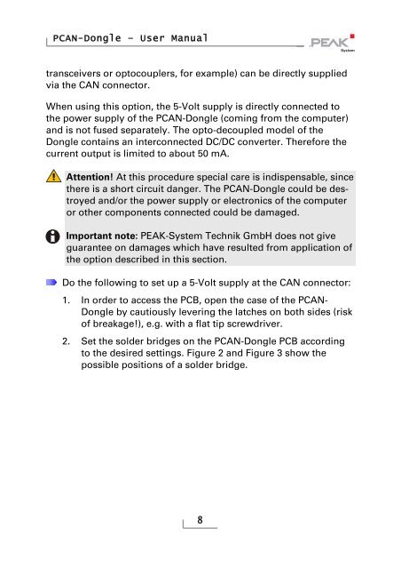
transceivers or optocouplers, for example) can be directly supplied<br />
via the CAN connector.<br />
When using this option, the 5-Volt supply is directly connected to<br />
the power supply of the <strong>PCAN</strong>-<strong>Dongle</strong> (coming from the computer)<br />
and is not fused separately. The opto-decoupled model of the<br />
<strong>Dongle</strong> contains an interconnected DC/DC converter. Therefore the<br />
current output is limited to about 50 mA.<br />
Attention! At this procedure special care is indispensable, since<br />
there is a short circuit danger. The <strong>PCAN</strong>-<strong>Dongle</strong> could be destroyed<br />
and/or the power supply or electronics of the computer<br />
or other components connected could be damaged.<br />
Important note: <strong>PEAK</strong>-<strong>System</strong> Technik GmbH does not give<br />
guarantee on damages which have resulted from application of<br />
the option described in this section.<br />
Do the following to set up a 5-Volt supply at the CAN connector:<br />
1. In order to access the PCB, open the case of the <strong>PCAN</strong>-<br />
<strong>Dongle</strong> by cautiously levering the latches on both sides (risk<br />
of breakage!), e.g. with a flat tip screwdriver.<br />
2. Set the solder bridges on the <strong>PCAN</strong>-<strong>Dongle</strong> PCB according<br />
to the desired settings. Figure 2 and Figure 3 show the<br />
possible positions of a solder bridge.<br />
8
![English - Low Quality [7.2 MB] - PEAK-System](https://img.yumpu.com/5931738/1/184x260/english-low-quality-72-mb-peak-system.jpg?quality=85)