PCAN-Dongle - User Manual - PEAK-System
PCAN-Dongle - User Manual - PEAK-System
PCAN-Dongle - User Manual - PEAK-System

You also want an ePaper? Increase the reach of your titles
YUMPU automatically turns print PDFs into web optimized ePapers that Google loves.
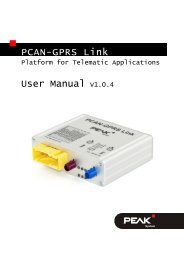
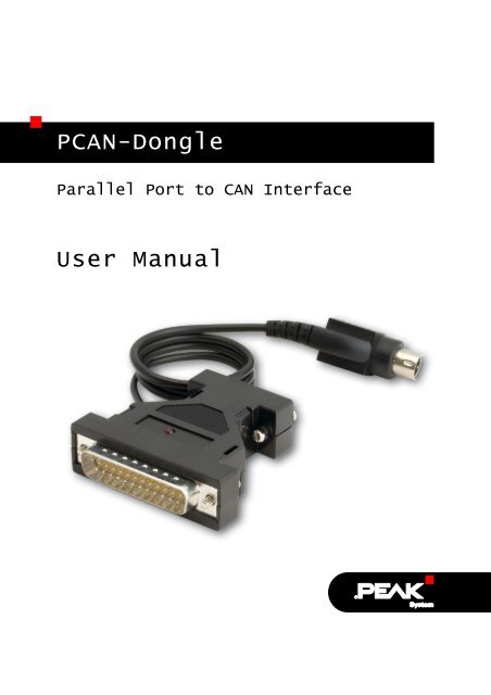
<strong>PCAN</strong>-<strong>Dongle</strong><br />
Parallel Port to CAN Interface<br />
<strong>User</strong> <strong>Manual</strong>
<strong>PCAN</strong>-<strong>Dongle</strong> – <strong>User</strong> <strong>Manual</strong><br />
Products taken into account<br />
Product Name Model Item Number<br />
<strong>PCAN</strong>-<strong>Dongle</strong> DIN IPEH-002015<br />
<strong>PCAN</strong>-<strong>Dongle</strong> PS/2 IPEH-002019<br />
<strong>PCAN</strong>-<strong>Dongle</strong> opto-decoupled PS/2 IPEH-002020<br />
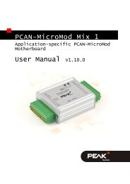
The cover picture shows the <strong>PCAN</strong>-<strong>Dongle</strong> opto-decoupled. The other models have a<br />
case with silver-colored coating.<br />
Product names mentioned in this manual may be the trademarks or registered<br />
trademarks of their respective companies. They are not explicitly marked by “” and<br />
“®”.<br />
© 2011 <strong>PEAK</strong>-<strong>System</strong> Technik GmbH<br />
<strong>PEAK</strong>-<strong>System</strong> Technik GmbH<br />
Otto-Roehm-Strasse 69<br />
D-64293 Darmstadt<br />
Germany<br />
Phone: +49 (0)6151-8173-20<br />
Fax: +49 (0)6151-8173-29<br />
www.peak-system.com<br />
info@peak-system.com<br />
Issued 2011-10-12<br />
2
<strong>PCAN</strong>-<strong>Dongle</strong> – <strong>User</strong> <strong>Manual</strong><br />
Contents<br />
1 Introduction 4<br />
1.1 Properties at a Glance 4<br />
1.2 <strong>System</strong> Requirements 5<br />
1.3 Scope of Supply 5<br />
2 Hardware Installation 6<br />
2.1 Connecting to the Computer 6<br />
2.2 Connecting a CAN Bus 7<br />
2.3 5-Volt Supply at the CAN Connector 7<br />
3 Software Setup 10<br />
4 Operation 11<br />
4.1 Prerequisites for the Operation 11<br />
4.2 Interface Information 12<br />
4.3 Operating Modes 14<br />
4.4 <strong>PCAN</strong>-View for Windows 15<br />
5 Linking Own Programs with <strong>PCAN</strong>-Light 18<br />
6 Frequently Asked Questions (FAQ) 19<br />
7 Technical Specifications 20<br />
Appendix A CE Certificate 22<br />
Appendix B Quick Reference 23<br />
3
<strong>PCAN</strong>-<strong>Dongle</strong> – <strong>User</strong> <strong>Manual</strong><br />
1 Introduction<br />
Tip: At the end of this manual (Appendix B) you can find a<br />
Quick Reference with brief information about the installation<br />
and operation of the <strong>PCAN</strong>-<strong>Dongle</strong>.<br />
The <strong>PCAN</strong>-<strong>Dongle</strong> allows the connection of a CAN bus to the<br />
parallel port of a computer. Therefore the computer can easily be<br />
integrated into a High-speed CAN network.<br />
The opto-decoupled model of the <strong>PCAN</strong>-<strong>Dongle</strong> additionally<br />
contains a galvanic isolation. An isolation of up to 500 V between<br />
the computer and the CAN parts of the interface is achieved by use<br />
of a DC/DC converter and an optocoupler.<br />
Note: This manual refers to both the <strong>PCAN</strong>-<strong>Dongle</strong> standard<br />
model as well as the one with galvanic isolation. Differences at<br />
use and at the technical specifications are mentioned<br />
accordingly in this manual.<br />
1.1 Properties at a Glance<br />
Connection of a High-speed CAN network (CAN specifications<br />
2.0A and 2.0B) to a computer<br />
Use of any parallel port that is capable of interrupts<br />
Supports all interrupt and port address settings for the parallel<br />
interface<br />
Supports the standard and the ECP mode of a parallel interface<br />
Equipped with the CAN controller SJA1000T by Philips/EXP<br />
CAN transfer rate up to 1 MBit/s<br />
4
<strong>PCAN</strong>-<strong>Dongle</strong> – <strong>User</strong> <strong>Manual</strong><br />
CAN connection 9-pin D-Sub male, pin assignment according to<br />
CiA recommendation DS 102<br />
Galvanic isolation up to 500 V for the CAN interface (only optodecoupled<br />
model)<br />
Power supply (5 V) via cable with T-piece for keyboard<br />
connector (DIN or PS/2)<br />
Support for operating systems Windows (starting with 2000) and<br />
Linux<br />
Note: This manual describes the use of the <strong>PCAN</strong>-<strong>Dongle</strong> with<br />
Windows. You can find device drivers for Linux and the<br />
corresponding information on <strong>PEAK</strong>-<strong>System</strong>'s website under<br />
www.peak-system.com/linux.<br />
1.2 <strong>System</strong> Requirements<br />
The following prerequisites must be given, so that the <strong>PCAN</strong>-<strong>Dongle</strong><br />
can be used properly:<br />
A free parallel port (D-Sub, 25 pins) at the computer, capable of<br />
interrupts<br />
Operating system Windows (Vista, XP SP2, 2000 SP4) or Linux<br />
1.3 Scope of Supply<br />
The scope of supply normally consists of the following parts:<br />
<strong>PCAN</strong>-<strong>Dongle</strong> (case with two ports and a cable with T-piece for<br />
DIN or PS/2 keyboard connector)<br />
CD-ROM with software (drivers, utilities), programming<br />
examples, and documentation<br />
5
<strong>PCAN</strong>-<strong>Dongle</strong> – <strong>User</strong> <strong>Manual</strong><br />
2 Hardware Installation<br />
2.1 Connecting to the Computer<br />
1. Make sure that the computer is turned off.<br />
2. Connect the <strong>PCAN</strong>-<strong>Dongle</strong> with the wider port (25 pins) to<br />
the free parallel port at the computer.<br />
3. Pull the keyboard connector from the corresponding port at<br />
the computer.<br />
4. Connect the T-piece at the cable of the <strong>PCAN</strong>-<strong>Dongle</strong> to the<br />
keyboard port.<br />
5. Now reconnect the keyboard to the free end of the T-piece.<br />
A configuration of the hardware is not needed. However, you<br />
should check the settings for the parallel interface in the computer's<br />
BIOS setup.<br />
If the computer has a parallel interface with EPP as well as ECP<br />
properties, the corresponding setting in the BIOS set-up should be<br />
“ECP” (not “EPP” and not “EPP+ECP”). Although the extended<br />
properties of the <strong>PCAN</strong>-<strong>Dongle</strong> usually will work with the lastmentioned<br />
setting some systems may have problems with it.<br />
Therefore the setting for the “pure” ECP mode should be preferred.<br />
Further information about the different operating modes of the<br />
<strong>PCAN</strong>-<strong>Dongle</strong> can be found in chapter 4.3 Operating Modes on page<br />
14.<br />
6
<strong>PCAN</strong>-<strong>Dongle</strong> – <strong>User</strong> <strong>Manual</strong><br />
First Test<br />
After turning on the computer the red LED at the <strong>PCAN</strong>-<strong>Dongle</strong><br />
must be permanently on. This indicates that the power supply for<br />
the <strong>PCAN</strong>-<strong>Dongle</strong> is correct.<br />
Attention! Don't remove <strong>PCAN</strong>-<strong>Dongle</strong> from the computer<br />
while powered on (red LED on <strong>PCAN</strong>-<strong>Dongle</strong> is lit). Electronic<br />
parts of the <strong>PCAN</strong>-<strong>Dongle</strong> or the computer's parallel interface<br />
may be harmed.<br />
2.2 Connecting a CAN Bus<br />
A High-speed CAN bus (ISO 11898-2) is connected to the 9-pin<br />
D-Sub port. The pin assignment corresponds to the CiA<br />
recommendation DS 102-1.<br />
Figure 1: Pin assignment HS-CAN<br />
(view onto connector of the <strong>PCAN</strong>-<strong>Dongle</strong>)<br />
2.3 5-Volt Supply at the CAN Connector<br />
A 5-Volt supply can optionally be routed to pin 1 and/or pin 9 of the<br />
CAN connector (<strong>PCAN</strong>-<strong>Dongle</strong> opto-decoupled: pin 1 only) by<br />
setting solder bridges on the <strong>PCAN</strong>-<strong>Dongle</strong> PCB (<strong>Dongle</strong> case<br />
opened). Thus devices with low power consumption (external<br />
7
<strong>PCAN</strong>-<strong>Dongle</strong> – <strong>User</strong> <strong>Manual</strong><br />
transceivers or optocouplers, for example) can be directly supplied<br />
via the CAN connector.<br />
When using this option, the 5-Volt supply is directly connected to<br />
the power supply of the <strong>PCAN</strong>-<strong>Dongle</strong> (coming from the computer)<br />
and is not fused separately. The opto-decoupled model of the<br />
<strong>Dongle</strong> contains an interconnected DC/DC converter. Therefore the<br />
current output is limited to about 50 mA.<br />
Attention! At this procedure special care is indispensable, since<br />
there is a short circuit danger. The <strong>PCAN</strong>-<strong>Dongle</strong> could be destroyed<br />
and/or the power supply or electronics of the computer<br />
or other components connected could be damaged.<br />
Important note: <strong>PEAK</strong>-<strong>System</strong> Technik GmbH does not give<br />
guarantee on damages which have resulted from application of<br />
the option described in this section.<br />
Do the following to set up a 5-Volt supply at the CAN connector:<br />
1. In order to access the PCB, open the case of the <strong>PCAN</strong>-<br />
<strong>Dongle</strong> by cautiously levering the latches on both sides (risk<br />
of breakage!), e.g. with a flat tip screwdriver.<br />
2. Set the solder bridges on the <strong>PCAN</strong>-<strong>Dongle</strong> PCB according<br />
to the desired settings. Figure 2 and Figure 3 show the<br />
possible positions of a solder bridge.<br />
8
<strong>PCAN</strong>-<strong>Dongle</strong> – <strong>User</strong> <strong>Manual</strong><br />
+5 Volt at the CAN connector:<br />
Figure 2:<br />
PCB <strong>PCAN</strong>-<strong>Dongle</strong> (bottom view):<br />
JP9, 2-1 (as shown) → Pin 1;<br />
JP9, 2-3 → Pin 9<br />
9<br />
Figure 3:<br />
PCB <strong>PCAN</strong>-<strong>Dongle</strong> opto-decoupled<br />
(top view):<br />
short-circuit pos. R11 → Pin 1<br />
3. For reassembly place the PCB overhead onto the top part of<br />
the case. Make sure that the cable is lying in the side cut-out<br />
with the strain relief inside the case, and that the LED is<br />
placed in the corresponding hole of the top part of the case.<br />
4. Push the bottom part of the case onto the top part (the<br />
latches click in).
<strong>PCAN</strong>-<strong>Dongle</strong> – <strong>User</strong> <strong>Manual</strong><br />
3 Software Setup<br />
Under Windows a driver is needed that can access the <strong>PCAN</strong>-<br />
<strong>Dongle</strong> and that provides the interface for Windows software.<br />
Beside the mentioned device driver the CAN monitor <strong>PCAN</strong>-View<br />
for Windows can also set up.<br />
Do the following to setup the driver and, if applicable, additional<br />
software:<br />
1. Please make sure that you are logged in as user with<br />
administrator privileges (not needed for normal use of the<br />
<strong>PCAN</strong>-<strong>Dongle</strong> later on).<br />
2. Insert the supplied CD-ROM into the drive of the computer.<br />
Usually a navigation program appears a few moments later.<br />
If not, start the file Intro.exe from the root directory of the<br />
CD-ROM.<br />
3. Navigate through the menus to the driver installation for the<br />
<strong>PCAN</strong>-<strong>Dongle</strong> (English > Drivers > <strong>PCAN</strong>-<strong>Dongle</strong>). Click on<br />
Install now afterwards. The setup program for the driver is<br />
executed. Under Windows Vista you may need to confirm<br />
the note about the execution with elevated rights.<br />
4. Follow the instructions of the setup program.<br />
10
<strong>PCAN</strong>-<strong>Dongle</strong> – <strong>User</strong> <strong>Manual</strong><br />
4 Operation<br />
4.1 Prerequisites for the Operation<br />
Under Windows you must explicitly determine the use of an<br />
interrupt for the parallel interface. This is done in the Windows<br />
Device Manager.<br />
Do the following to assign an interrupt to the parallel interface<br />
under Windows:<br />
1. Open the Windows Device Manager.<br />
One way to do this is by accessing the context menu of the<br />
desktop icon My Computer or Computer (right mouse click),<br />
by selecting the menu item Manage, and then by selecting<br />
the entry Device Manager from the tree view on the right.<br />
2. Under Ports (COM & LPT) in the tree view of the Device<br />
Manager double click on the entry Printer Port (LPTx) or ECP<br />
Printer Port (LPTx).<br />
Figure 4: Entry in the Device Manager for the printer port<br />
3. Select the tab Port Settings.<br />
4. Activate the option Use any interrupt assigned to the port.<br />
11
<strong>PCAN</strong>-<strong>Dongle</strong> – <strong>User</strong> <strong>Manual</strong><br />
Figure 5: Indicating the use of an interrupt<br />
4.2 Interface Information<br />
For the initialization of the <strong>PCAN</strong>-<strong>Dongle</strong> during the start of an<br />
application you need information about the used interrupt and port<br />
address of the parallel interface.<br />
Do the following to find out the interrupt and the I/O range used<br />
by the parallel interface:<br />
1. Open the Windows Device Manager.<br />
One way to do this is by accessing the context menu of the<br />
desktop icon My Computer or Computer (right mouse click),<br />
by selecting the menu item Manage, and then by selecting<br />
the entry Device Manager from the tree view on the left.<br />
2. Under Ports (COM & LPT) in the tree view of the Device<br />
Manager double click on the entry Printer Port (LPTx) or ECP<br />
Printer Port (LPTx).<br />
12
<strong>PCAN</strong>-<strong>Dongle</strong> – <strong>User</strong> <strong>Manual</strong><br />
Figure 6: Entry in the Device Manager for the printer port<br />
3. Select the tab Resources.<br />
4. From the entries I/O Range (first value = port address) and<br />
Interrupt or IRQ in the list you can see the needed<br />
information. Write down this information for later use.<br />
Figure 7: Resource information about the parallel interface<br />
13
<strong>PCAN</strong>-<strong>Dongle</strong> – <strong>User</strong> <strong>Manual</strong><br />
4.3 Operating Modes<br />
The <strong>PCAN</strong>-<strong>Dongle</strong> can be used in one of four possible operating<br />
modes:<br />
Name of Operating<br />
Mode<br />
Alternative<br />
Identifier<br />
14<br />
Description<br />
Multiplex Mode <strong>PEAK</strong> <strong>Dongle</strong>-CAN Standard Parallel Port (SPP)<br />
EPP Mode <strong>PEAK</strong> <strong>Dongle</strong>-CAN<br />
EPP<br />
Extended Capability Port (ECP)<br />
Multiplex PeliCAN<br />
Mode<br />
<strong>PEAK</strong> <strong>Dongle</strong>-CAN<br />
SJA<br />
EPP PeliCAN Mode <strong>PEAK</strong> <strong>Dongle</strong>-CAN<br />
SJA EPP<br />
Standard Parallel Port (SPP),<br />
extended CAN functionality (CAN<br />
2.0B incl. 29-bit IDs)<br />
Extended Capability Port (ECP),<br />
extended CAN functionality (CAN<br />
2.0B incl. 29-bit IDs)<br />
The EPP PeliCAN Mode is recommended to gain the full CAN<br />
functionality at lowest possible computer system load. If this mode<br />
doesn't work correctly, you can fall back to one of the other<br />
operating modes. The Multiplex Mode should work on any system.<br />
Tip: You can find further information about the PeliCAN Mode<br />
in the data sheet for the CAN controller SJA1000 by Philips/EXP<br />
obtainable at the according website, for example.<br />
You can find information about activating an operating mode in the<br />
following section.
<strong>PCAN</strong>-<strong>Dongle</strong> – <strong>User</strong> <strong>Manual</strong><br />
4.4 <strong>PCAN</strong>-View for Windows<br />
<strong>PCAN</strong>-View for Windows is a simple CAN monitor for viewing and<br />
transmitting CAN messages.<br />
Figure 8: <strong>PCAN</strong>-View main window<br />
Installation<br />
You can install the application optionally during the driver setup<br />
procedure (see also chapter 3 Software Setup on page 10).<br />
Program Start<br />
In the Start menu of the Windows desktop you can find the entry<br />
“<strong>PCAN</strong> Hardware”. From there you can execute the program <strong>PCAN</strong>-<br />
View.<br />
A dialog for the selection of the CAN hardware as well as the setting<br />
of the CAN parameters appears after the program start.<br />
15
<strong>PCAN</strong>-<strong>Dongle</strong> – <strong>User</strong> <strong>Manual</strong><br />
Figure 9: Selection of the CAN specific parameters<br />
If no entry is in the list “Available CAN hardware” (for example at<br />
the first program start), you need to add one (administrator rights<br />
needed):<br />
1. Press the button Add. The dialog box “Add CAN hardware”<br />
appears.<br />
2. Select the connected hardware and the operating mode<br />
from the list “Type of CAN hardware”. If the mode of the<br />
parallel interface is set to ECP in the computer's BIOS setup,<br />
you can register the <strong>PCAN</strong>-<strong>Dongle</strong> as “<strong>PEAK</strong> <strong>Dongle</strong>-CAN<br />
SJA EPP”.<br />
16
<strong>PCAN</strong>-<strong>Dongle</strong> – <strong>User</strong> <strong>Manual</strong><br />
Figure 10: Selection of hardware resources<br />
3. Enter the port address and the interrupt of the used parallel<br />
interface established before (see section above).<br />
4. Confirm your input with OK.<br />
In the dialog box “Connect to CAN hardware” make further settings<br />
(baud rate and CAN message filter) for the created hardware entry.<br />
If you need further help after the program start, use the online help<br />
provided with the program (key [F1]).<br />
17
<strong>PCAN</strong>-<strong>Dongle</strong> – <strong>User</strong> <strong>Manual</strong><br />
5 Linking Own Programs with<br />
<strong>PCAN</strong>-Light<br />
On the supplied CD-ROM you can find files that are provided for<br />
software development. You can access them with the navigation<br />
program (button Programming). The files exclusively serve the<br />
linking of own programs to hardware by <strong>PEAK</strong>-<strong>System</strong> with the help<br />
of the installed device driver under Windows.<br />
Further more the CD-ROM contains header files and examples for<br />
creating own applications in conjunction with the <strong>PCAN</strong>-Light<br />
drivers. Please read the detailed documentation of the interface<br />
(API) in each header file.<br />
Tip: You can find further information in the file<br />
<strong>PCAN</strong>Light_enu.chm (Windows Help file) on the CD-ROM.<br />
Notes about the License<br />
Device drivers, the interface DLL, and further files needed for linking<br />
are property of the <strong>PEAK</strong>-<strong>System</strong> Technik GmbH (<strong>PEAK</strong>-<strong>System</strong>)<br />
and may be used only in connection with a hardware component<br />
purchased from <strong>PEAK</strong>-<strong>System</strong> or one of its partners. If a CAN<br />
hardware component of third party suppliers should be compatible<br />
to one of <strong>PEAK</strong>-<strong>System</strong>, then you are not allowed to use or to pass<br />
on the driver software of <strong>PEAK</strong>-<strong>System</strong>.<br />
<strong>PEAK</strong>-<strong>System</strong> assumes no liability and no support for the <strong>PCAN</strong>-<br />
Light driver software and the necessary interface files. If third party<br />
suppliers develop software based on the <strong>PCAN</strong>-Light driver and<br />
problems occur during use of this software, please, consult the<br />
software provider. To obtain development support, you need to<br />
own a <strong>PCAN</strong>-Developer or <strong>PCAN</strong>-Evaluation version.<br />
18
<strong>PCAN</strong>-<strong>Dongle</strong> – <strong>User</strong> <strong>Manual</strong><br />
6 Frequently Asked Questions<br />
(FAQ)<br />
Question Answer<br />
In the computer's BIOS<br />
setup the parallel port<br />
setting shows ECP but the<br />
<strong>PCAN</strong>-<strong>Dongle</strong> works with<br />
the EPP mode. Is this<br />
correct?<br />
Can a printer still be<br />
connected to the <strong>PCAN</strong>-<br />
<strong>Dongle</strong>?<br />
Is it possible to supply the<br />
<strong>PCAN</strong>-<strong>Dongle</strong> PS/2 also via<br />
the computer's mouse<br />
connector?<br />
I have problems running<br />
the <strong>PCAN</strong>-<strong>Dongle</strong> under<br />
Windows Vista/XP/2000.<br />
Yes, it is. The naming of the<br />
operating mode EPP of the <strong>PCAN</strong>-<br />
<strong>Dongle</strong> has historical causes. The<br />
parallel interface at the computer<br />
went through various developments<br />
in the nineties. Only the EPP<br />
extension existed during the time,<br />
when the <strong>PCAN</strong>-<strong>Dongle</strong> arose. With<br />
version 1.9 the EPP extension already<br />
had similarities to the ECP extension,<br />
which is usually used in computers<br />
today. The name of the operating<br />
mode EPP was kept for the <strong>PCAN</strong>-<br />
<strong>Dongle</strong>.<br />
No. The <strong>PCAN</strong>-<strong>Dongle</strong> doesn't offer<br />
any possibility to connect through the<br />
parallel interface for the printer.<br />
Yes.<br />
The driver files <strong>PEAK</strong>CAN.SYS and<br />
<strong>PCAN</strong>_DNG.SYS must be available at<br />
least in version 2.30. You can<br />
determine the currently used driver<br />
version e.g. with the About dialog<br />
box in <strong>PCAN</strong>-View (menu command<br />
Help | About).<br />
19
<strong>PCAN</strong>-<strong>Dongle</strong> – <strong>User</strong> <strong>Manual</strong><br />
7 Technical Specifications<br />
Supply<br />
Supply voltage +5 V DC<br />
Current consumption <strong>PCAN</strong>-<strong>Dongle</strong>: max. 80 mA<br />
<strong>PCAN</strong>-<strong>Dongle</strong> opto-decoupled: max. 140 mA<br />
Connectors<br />
Supply Cable to the keyboard jack of the computer, length<br />
about 50 cm/20 inches<br />
Computer D-Sub (m), 25 pins (to standard parallel port)<br />
CAN D-Sub (m), 9 pins<br />
Pin assignment according to CiA recommendation<br />
DS 102-1<br />
IPEH-002020: galvanic isolation up to 500 V<br />
CAN<br />
Specification ISO 11898-2<br />
High-speed CAN (up to 1 MBit/s)<br />
2.0A (standard format) and 2.0B (extended format)<br />
Controller Philips SJA1000T<br />
Transceiver Philips PCA82C251<br />
Environment<br />
Operating temperature 0 – 60 °C (32 – 140 °F)<br />
Storage temperature -20 – +80 °C (-4 – 176 °F)<br />
Relative humidity 15 – 90 %, not condensing<br />
EMC EN 55024:2003-10<br />
EN 55022:2008-05<br />
EC directive 2004/108/EG<br />
Continued on the next page<br />
20
<strong>PCAN</strong>-<strong>Dongle</strong> – <strong>User</strong> <strong>Manual</strong><br />
Measures<br />
Size 56 x 18 x 62 mm (2 3/16 x 11/16 x 2 7/16 Inches)<br />
Weight <strong>PCAN</strong>-<strong>Dongle</strong> (DIN): 52 g (1.83 oz.)<br />
<strong>PCAN</strong>-<strong>Dongle</strong> (PS/2): 51 g (1.80 oz.)<br />
<strong>PCAN</strong>-<strong>Dongle</strong> opto-decoupled: 52 g (1.83 oz.)<br />
21
<strong>PCAN</strong>-<strong>Dongle</strong> – <strong>User</strong> <strong>Manual</strong><br />
Appendix A CE Certificate<br />
22
<strong>PCAN</strong>-<strong>Dongle</strong> – <strong>User</strong> <strong>Manual</strong><br />
Appendix B Quick Reference<br />
Hardware Installation<br />
Connect the <strong>PCAN</strong>-<strong>Dongle</strong> to the computer's parallel port, insert the<br />
T-piece at the cable's end between the keyboard port at the<br />
computer and the keyboard connector (for power supply). When the<br />
computer is turned on, the red LED indicates an existing power<br />
supply.<br />
Software setup and startup under Windows<br />
Execute the driver installation program from the supplied CD-ROM.<br />
Restart Windows after the setup procedure.<br />
Run the CAN monitor <strong>PCAN</strong>-View for Windows from the Start menu<br />
as a sample application for accessing the <strong>PCAN</strong>-<strong>Dongle</strong>. Get the<br />
parameters of the parallel interface (I/O address, interrupt) needed<br />
for initialization of the <strong>PCAN</strong>-<strong>Dongle</strong> from Windows' Device<br />
Manager.<br />
HS-CAN connector (D-Sub, 9 pins)<br />
23
![English - Low Quality [7.2 MB] - PEAK-System](https://img.yumpu.com/5931738/1/184x260/english-low-quality-72-mb-peak-system.jpg?quality=85)