Mathematics for Computer Science
e9ck2Ar
e9ck2Ar

You also want an ePaper? Increase the reach of your titles
YUMPU automatically turns print PDFs into web optimized ePapers that Google loves.
“mcs” — 2017/3/3 — 11:21 — page 428 — #436<br />
428<br />
Chapter 11<br />
Communication Networks<br />
IN OUT IN OUT IN OUT IN OUT<br />
0 0 1 1 2 2 3 3<br />
IN OUT IN OUT IN OUT IN OUT<br />
0 0 1 1 2 2 3 3<br />
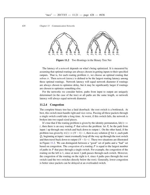
Figure 11.2<br />
Two Routings in the Binary Tree Net<br />
The latency of a network depends on what’s being optimized. It is measured by<br />
assuming that optimal routings are always chosen in getting inputs to their specified<br />
outputs. That is, <strong>for</strong> each routing problem , we choose an optimal routing that<br />
solves . Then network latency is defined to be the largest routing latency among<br />
these optimal routings. Network latency will equal network diameter if routings<br />
are always chosen to optimize delay, but it may be significantly larger if routings<br />
are chosen to optimize something else.<br />
For the networks we consider below, paths from input to output are uniquely<br />
determined (in the case of the tree) or all paths are the same length, so network<br />
latency will always equal network diameter.<br />
11.2.4 Congestion<br />
The complete binary tree has a fatal drawback: the root switch is a bottleneck. At<br />
best, this switch must handle right and vice-versa. Passing all these packets through<br />
a single switch could take a long time. At worst, if this switch fails, the network is<br />
broken into two equal-sized pieces.<br />
It’s true that if the routing problem is given by the identity permutation, Id.i/WWD<br />
i, then there is an easy routing P that solves the problem: let P i be the path from<br />
input i up through one switch and back down to output i. On the other hand, if the<br />
problem was given by .i/ WWD .N 1/ i, then in any solution Q <strong>for</strong> , each path<br />
Q i beginning at input i must eventually loop all the way up through the root switch<br />
and then travel back down to output .N 1/ i. These two situations are illustrated<br />
in Figure 11.2. We can distinguish between a “good” set of paths and a “bad” set<br />
based on congestion. The congestion of a routing P is equal to the largest number<br />
of paths in P that pass through a single switch. For example, the congestion of the<br />
routing on the left is 1, since at most 1 path passes through each switch. However,<br />
the congestion of the routing on the right is 4, since 4 paths pass through the root<br />
switch (and the two switches directly below the root). Generally, lower congestion<br />
is better since packets can be delayed at an overloaded switch.