

ORION Commercial 'LULA' Elevator - Advanced Lift Solutions
ORION Commercial 'LULA' Elevator - Advanced Lift Solutions
ORION Commercial 'LULA' Elevator - Advanced Lift Solutions

Create successful ePaper yourself
Turn your PDF publications into a flip-book with our unique Google optimized e-Paper software.
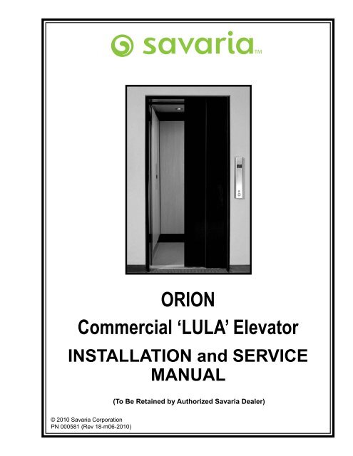
<strong>ORION</strong><br />
<strong>Commercial</strong> ‘LULA’ <strong>Elevator</strong><br />
INSTALLATION and SERVICE<br />
MANUAL<br />
© 2010 Savaria Corporation<br />
PN 000581 (Rev 18-m06-2010)<br />
(To Be Retained by Authorized Savaria Dealer)
Technical Documentation Modifications and Additions<br />
Orion <strong>Commercial</strong> ‘LULA’ <strong>Elevator</strong> Installation and Service Manual (PN 000581, Rev. 18-m06-2010)<br />
Note: Modifications between revisions are marked M; additions between revisions are marked A.<br />
Section Details<br />
Section 5.9, page 60<br />
Added detailed drawing of hardware for overspeed<br />
governor cable tensioner assembly<br />
Section 5.11, page 63 Updated Tape Reader installation section M<br />
Section 8.1, page 106 Updated Pro-Auto Door Operator installation section M<br />
Appendix C<br />
IMPORtANt<br />
the following details and provided documents replace or augment the published manuals<br />
and schematics. the most recent engineering changes and enhancements are reflected in<br />
the notes below.<br />
Updated Virginia PLC Controller information to reflect<br />
latest version<br />
PN# 301405 ©Savaria Concord <strong>Lift</strong>s Inc.<br />
1 of 1<br />
M<br />
M
1<br />
8<br />
15<br />
22<br />
31<br />
Install Rails and Rail Brackets<br />
Manual Ref. Sect. 3.1, pg. 18<br />
Estimated Time 8 hrs<br />
Completed?<br />
Install Hydraulic Piping and<br />
Overspeed Valve OR Hose<br />
Manual Ref. Sect. 5.0-5.1,<br />
pg. 45-47<br />
Estimated Time 0.5 - 4 hrs<br />
Completed?<br />
Install Halfway Junction Box<br />
Manual Ref. Sect. 7.1-7.2,<br />
pg. 93<br />
Estimated Time 15 mins.<br />
Completed?<br />
Connect Wiring at Hoistway<br />
Junction Box<br />
Manual Ref. Sect. 7.4 pg. 95<br />
Estimated Time 15 mins.<br />
Completed?<br />
Install Travelling Cables<br />
Manual Ref. Sect. 7.3, pg. 94<br />
Estimated Time 0.5 hrs<br />
Completed?<br />
2<br />
Time dependant on<br />
distance between hoistway<br />
and machine room & on<br />
hose or hard piping req’s<br />
16<br />
23<br />
Assemble Split Cylinder IF<br />
Required<br />
Manual Ref. Sect. 3.2, pg. 26<br />
Estimated Time 2 hrs<br />
Completed?<br />
9<br />
Install Tape & Tape Reader<br />
Manual Ref. Sect. 5.11, pg. 63<br />
Estimated Time 0.5 hrs<br />
Install Entrance Frames & Doors<br />
Manual Ref. Sect. 8.0, pg. 104<br />
or 2 Speed Door Manual<br />
Estimated Time 4 - 8 hrs<br />
32<br />
Completed?<br />
Completed?<br />
Time dependant on number<br />
of landings and/or doors &<br />
operators<br />
Connect Temporary<br />
Run Buttons<br />
Manual Ref. Sect. 5.2, pg. 50<br />
Connect Controller and<br />
COP Electrical Wiring<br />
Estimated Time 0.5 hrs<br />
Completed?<br />
Manual Ref. Sect. 7.0, pg. 92<br />
& Appendix A<br />
Estimated Time 2 hrs<br />
Completed?<br />
Install Jack Unit and Upstand<br />
Manual Ref. Sect. 3.3, pg. 30<br />
Estimated Time 1 hr<br />
Completed?<br />
Bleed Cylinder<br />
Manual Ref. Sect. 5.3, pg. 51<br />
Estimated Time 5 mins.<br />
Completed?<br />
Orion <strong>Commercial</strong> ‘LULA’ <strong>Elevator</strong> Step-by-Step Installation Guide<br />
Refer to Orion <strong>Commercial</strong> ‘LULA’ <strong>Elevator</strong> Installation and Service Manual Part Number 000581<br />
3<br />
17<br />
10<br />
Position Floor Magnets<br />
Manual Ref. Sect. 5.11, pg. 64<br />
Estimated Time 10 mins.<br />
Completed?<br />
Hoistway Entrance Door<br />
33<br />
Type?<br />
Program the PLC<br />
24<br />
25<br />
Manual Ref. Appendix C,<br />
Estimated Time 15 mins.<br />
Completed?<br />
4<br />
18<br />
Install Bumpers OR Buffers<br />
Manual Ref. Sect. 3.7, pg. 42<br />
Estimated Time 0.5 hrs<br />
Completed?<br />
11<br />
Install Limit Switches<br />
and Cams<br />
Manual Ref. Sect. 5.12, pg. 66<br />
Estimated Time 15 mins.<br />
Completed?<br />
Assemble & Plumb<br />
Entrance Frames (2 Spd.)<br />
Refer to 2 Speed Door Manual<br />
Estimated Time 6 - 12 hrs<br />
Completed?<br />
Secure Pro-Door Assembly<br />
& Wire Operator if req’d<br />
Manual Ref. Sect. 8.1 pg. 106<br />
Estimated Time 3 - 6 hrs<br />
Completed?<br />
34<br />
Install Aircraft Cable<br />
Manual Ref. Sect. 5.5, pg. 53<br />
Estimated Time 0.5 hrs<br />
Completed?<br />
Power ON and Test <strong>Elevator</strong><br />
Manual Ref. Sect. 7.8 & 12,<br />
pg. 103 & 131<br />
Estimated Time 1 hrs<br />
Completed?<br />
Time<br />
dependant<br />
on number<br />
of landings<br />
5<br />
19<br />
26<br />
27<br />
Assemble Sling<br />
Manual Ref. Sect. 3.5, pg. 35<br />
Estimated Time 2 hrs<br />
Completed?<br />
12<br />
Install & Wire Pit Switch<br />
Manual Ref. Sect. 5.10, pg. 62<br />
Estimated Time 4 to 8 hrs<br />
Completed?<br />
Secure Door Panels to<br />
35<br />
Header & Plumb<br />
Refer to 2 Speed Door Manual<br />
Estimated Time 2-8 hrs<br />
Completed?<br />
Adjust Pro-Lock<br />
& Door Closure if req’d<br />
Adjust Roping Position<br />
Manual Ref. Sect. 5.4, pg. 52<br />
Estimated Time 0.5 hrs<br />
Completed?<br />
Manual Ref. Sect. 9.0, pg. 112<br />
Estimated Time 1- 2 hrs<br />
Completed?<br />
Check Working Pressure<br />
w/Slack Rope Monitor Valve<br />
6<br />
20<br />
Manual Ref. Sect. 10.3, pg. 120<br />
Estimated Time 0.5 hrs<br />
Completed?<br />
Fill Oil Reservoir<br />
Manual Ref. Sect. 5.0, pg. 45<br />
Estimated Time 15 mins.<br />
Completed?<br />
13<br />
Install utility boxes for<br />
landing stations & hoistway wiring<br />
Site Dependant (est. 1 hr)<br />
Completed?<br />
28<br />
36<br />
Install Platform<br />
Manual Ref. Sect. 5.7, pg. 56<br />
Estimated Time 0.5 hrs<br />
Completed?<br />
2 Speed Doors are only installed with<br />
2 Speed Operators<br />
Cab Assembly<br />
Demonstrate the operation of the elevator to the<br />
customer, provide dealer information in the Owner’s<br />
Manual and warranty details as necessary.<br />
7<br />
Time dependant on<br />
distance between hoistway<br />
and machine room<br />
Manual Ref. Sect. 6.0, pg. 68<br />
Estimated Time 2 hrs<br />
Completed?<br />
Pro- Doors are only installed with Pro-Locks &<br />
Auto Gate Operators<br />
Set Over Pressure Relief Valve<br />
Manual Ref. Sect. 10.1,<br />
pg. 115<br />
Estimated Time 0.5 hrs<br />
Completed?<br />
NOTE<br />
Mount Controller on Tank<br />
and Connect Main Power Supply<br />
Manual Ref. Sect. 4.0 & 7.2,<br />
TSSA Test Redundancy Circuit<br />
(Ontario, Canada ONLY)<br />
Manual Ref. Sect. 15,<br />
pg. 133<br />
Estimated Time 1 hrs<br />
Completed?<br />
Tasks are shown sequentially for convenience. Experienced teams can complete many steps in parallel, reducing the overall installation time.<br />
38<br />
pg. 44 & 93<br />
Estimated Time 0.5 hrs<br />
Completed?<br />
14<br />
21<br />
37<br />
Set Safety Brake, Install Pit Prop<br />
& Overspeed Governor<br />
Manual Ref. Sect. 5.6-5.9,<br />
pg. 55-59<br />
Estimated Time 0.5 hrs<br />
Completed?<br />
Run Wiring between<br />
Landing Station to Controller<br />
Manual Ref. Sect. 7.5, pg. 100<br />
Estimated Time 2 - 8 hrs<br />
29<br />
30<br />
Completed?<br />
2 Speed Doors &<br />
2 Speed Door Operator<br />
Refer to 2 Speed Door Manual<br />
Estimated Time 4 - 8 hrs<br />
Auto-Gate & Porta-Gate Operator<br />
Manual Ref. Sect. 6.4 - 6.5,<br />
Adjust Valve Speeds<br />
Manual Ref. Sect. 10.6-11.2<br />
pg. 123-130<br />
Estimated Time 0.5 hrs<br />
Completed?<br />
Completed?<br />
pg. 76-81<br />
Estimated Time 1 - 2 hrs<br />
Completed?
IMPORTANT<br />
This Orion <strong>Commercial</strong> “LU/LA” <strong>Elevator</strong> should be installed, maintained and<br />
serviced by authorized Savaria dealers only.<br />
The authorized Savaria dealer should refer to this manual for installation,<br />
maintenance, service and repair instructions.<br />
The owner is responsible for ensuring the ongoing safe operating condition of the<br />
Orion <strong>Elevator</strong> through proper maintenance and service. An inspection check or<br />
service call should be performed on a regular basis every six to twelve months by<br />
an authorized Savaria dealer (or as frequently as required by local jurisdiction).<br />
This manual should be retained by the Dealer for future reference. On completion<br />
of the installation, the dealer MUST provide the owner with the information below<br />
and ensure that it is recorded in the Owner’s Manual.<br />
Customer Name:<br />
Installing Dealer:<br />
Dealer’s Telephone Number:<br />
Date Installed:<br />
Serial/Job Number:<br />
Orion Installation Guide<br />
PN 000581 (18-m06-2010)<br />
FOR OWNER’S RECORDS<br />
1 of 145<br />
o r i o n co m m e r c i a l ‘l u l a’ e l e vato r
o r i o n co m m e r c i a l ‘l u l a’ e l e vat o r<br />
2 of 145<br />
TABLE Of CONTENTS<br />
IMPORTANT 1<br />
1.0 PRE-INSTALLATION INSTRUCTIONS AND NOTES 6<br />
1.1 INTRODUCTION 7<br />
1.2 GENERAL SPECIfICATIONS 8<br />
1.3 TOOLS AND MATERIALS REQUIRED 9<br />
1.4 ELEVATOR TERMINOLOGY 10<br />
2.0 INSTALLATION SAfETY TIPS 12<br />
2.1 PRELIMINARY CHECKS 13<br />
3.0 INITIAL INSTALLATION PROCEDURES 14<br />
3.1 RAIL INSTALLATION wITH SPEEDY JIG 18<br />
3.2 SPLIT CYLINDER ASSEMBLY (If EQUIPPED) 26<br />
3.2.1 Plunger Assembly 26<br />
3.2.2 Cylinder Barrel Assembly 27<br />
3.2.3 Split Cylinder Sanding 28<br />
3.3 JACK UNIT AND UPSTAND INSTALLATION 30<br />
3.4 SHEAVE/GUIDE YOKE INSTALLATION 33<br />
3.5 LIfT CHANNEL UPRIGHTS (STILES) AND SLING 35<br />
3.5.1 Stile Retainer Bracket Installation 39<br />
3.6 CAR TOP PROP INSTALLATION 39<br />
3.7 BUMPERS AND BUffERS 42<br />
4.0 CONNECTING THE POwER SUPPLY 44<br />
5.0 HYDRAULIC INSTALLATION 45<br />
5.0.1 filling the Reservoir 46<br />
5.1 OVERSPEED VALVE INSTALLATION AND TESTING 47<br />
5.1.1 Testing Instructions 48<br />
5.2 TEMPORARY RUN BUTTON INSTALLATION 50<br />
5.3 BLEEDING AIR fROM THE CYLINDER 51<br />
5.4 ROPING POSITION 52<br />
5.5 CABLE INSTALLATION 53<br />
5.6 PIT PROP 55<br />
Orion Installation Guide<br />
PN 000581 (18-m06-2010)
5.7 PLATfORM INSTALLATION 56<br />
5.8 SETTING THE SAfETIES 58<br />
5.9 OVERSPEED GOVERNOR 59<br />
5.10 PIT SwITCH INSTALLATION 62<br />
5.11 TAPE READER 63<br />
5.12 LIMIT SwITCH/fLOOR ZONE 66<br />
6.0 CAB ASSEMBLY 68<br />
6.1 CAR OPERATING PANEL (COP) INSTALLATION 73<br />
6.2 LIGHT CURTAIN INSTALLATION 74<br />
6.3 AUTOMATIC CAB LIGHTING 76<br />
6.4 CAB GATE INSTALLATION (If EQUIPPED) 76<br />
Orion Installation Guide<br />
PN 000581 (18-m06-2010)<br />
6.4.1 Gate Lock Channel 80<br />
6.5 PORTA - GATE OPERATOR INSTALLATION 81<br />
6.6 PORTA - GATE OPERATOR ELECTRICAL INSTALLATION 83<br />
6.7 PORTA - GATE TROUBLESHOOTING 87<br />
6.8 DUPLINE BOARD PROGRAMMING<br />
fOR DOOR AND GATE OPERATORS 88<br />
6.9 CTIS INSTALLATION 89<br />
6.9.1 2-Speed Door Operator Configuration 89<br />
6.9.2 Cab Gate and Swing Pro-Door Configuration 90<br />
7.0 ELECTRICAL INSTALLATION 92<br />
7.1 HOISTwAY JUNCTION BOx INSTALLATION 93<br />
7.2 HOISTwAY JUNCTION BOx CONNECTIONS 93<br />
7.3 TRAVELLING CABLES 94<br />
7.4 CONTROLLER LAYOUT AND wIRING 95<br />
7.4.1 Selecting the Controller Location and Environment 96<br />
7.4.2 Controller Grounding 97<br />
7.4.3 Machine Room Connections 97<br />
7.5 LANDING CONNECTIONS 100<br />
7.6 TERMINATION Of wIRING AT CONTROLLER 101<br />
7.7 CAR STATION CONNECTIONS 102<br />
7.8 POwER UP AND TEST THE ELEVATOR 103<br />
3 of 145<br />
o r i o n co m m e r c i a l ‘l u l a’ e l e vato r
o r i o n co m m e r c i a l ‘l u l a’ e l e vat o r<br />
8.0 INSTALLATION Of fIRE RATED PRO-DOORS 104<br />
4 of 145<br />
8.1 PRO- AUTO DOOR OPERATOR i INSTALLATION 106<br />
8.1.1 Operator Adjustment 106<br />
8.1.2 Electrical Installation 108<br />
8.1.3 Potentiometer (POT) Adjustments 109<br />
8.1.4 Setting the Cams 111<br />
9.0 PRO-LOCK INSTALLATION 112<br />
9.1 PRO-LOCK OPERATION 112<br />
9.2 PRO-LOCK ADJUSTMENT 112<br />
9.3 ELECTRICAL CONTACTS ADJUSTMENT 113<br />
10.0 ADJUSTING AND SETTING THE EPV VALVE 115<br />
10.1 SETTING THE OVER PRESSURE RELIEf VALVE 115<br />
10.2 PRESSURE GAUGE 120<br />
10.3 SLACK ROPE MONITOR VALVE 120<br />
10.4 LOw PRESSURE SwITCH 122<br />
10.5 SEQUENCE Of OPERATION Of THE EPV VALVE 122<br />
10.6 DETERMINING SPEEDS 123<br />
10.6.1 Set Speed without a Tachometer 123<br />
10.7 SPEED SETTING DESCRIPTIONS 125<br />
11.0 PROGRAMMING THE VALVE 126<br />
11.1 SETTING SPEED 128<br />
11.2 ERROR MESSAGES 130<br />
11.3 EPV MAINTENANCE 130<br />
12.0 TESTING OPERATION 131<br />
13.0 AUTOMATIC CAB LIGHTING 132<br />
14.0 BEfORE LEAVING THE JOB SITE 132<br />
15.0 TEST REDUNDANCY CIRCUIT (TSSA, ONTARIO ONLY) 133<br />
15.1 REDUNDANCY BACK-UP<br />
TESTING wITH fIREMAN SERVICE 133<br />
15.2 REDUNDANCY BACK-UP<br />
Orion Installation Guide<br />
PN 000581 (18-m06-2010)
APPENDIx A ELECTRICAL SCHEMATICS (shipped separately)<br />
APPENDIx B PARTS LIST B-1<br />
APPENDIx C VIRGINIA PLC CONTROLLER C-1<br />
1.0 PRE-INSTALLATION INSTRUCTIONS AND NOTES C-2<br />
2.0 CONTROLLER INSTALLATION AND wIRING C-3<br />
3.0 START-UP INSTRUCTIONS C-4<br />
4.0 fINAL ADJUSTMENTS C-9<br />
5.0 MICRO-PROCESSOR HARDwARE DESCRIPTION C-13<br />
6.0 SETUP GUIDE fOR PROGRAMMING THE ALLEN BRADLEY PLC C-18<br />
7.0 CONTROLLER NOMENCLATURE C-26<br />
8.0 PARTS LIST C-27<br />
9.0 CONTROLLER DIAGNOSTICS USING DAT C-28<br />
10.0 TROUBLESHOOTING SUGGESTIONS C-48<br />
11.0 DUPLINE SYSTEM: ENTERING CALLS fROM THE CONTROLLER C-51<br />
12.0 I/O BOARD REPLACEMENT C-52<br />
13.0 CONTROLLER MAINTENANCE C-57<br />
14.0 fREQUENTLY ASKED QUESTIONS C-58<br />
APPENDIx D CAB TYPES & GATE HANDING D-1<br />
APPENDIx E HANDS fREE TELEPHONE PROGRAMMING INSTRUCTIONS E-1<br />
APPENDIx f <strong>ORION</strong> CAB ASSEMBLY HARDwARE PRE-PACK f-1<br />
APPENDIx G NEw JERSEY fIRE SERVICE SwITCH wIRING G-1<br />
Orion Installation Guide<br />
PN 000581 (18-m06-2010)<br />
5 of 145<br />
o r i o n co m m e r c i a l ‘l u l a’ e l e vato r
o r i o n co m m e r c i a l ‘l u l a’ e l e vat o r<br />
1.0 PRE-INSTALLATION INSTRUCTIONS AND NOTES<br />
General Notes<br />
Important information is highlighted by the headings WARNING, CAUTION, or NOTE. These<br />
words are defined as follows:<br />
wARNING Warnings are used to indicate instructions, which if not followed correctly, will<br />
likely result in personal injury or substantial damage to equipment.<br />
CAUTION Cautions are used to indicate instructions or information, which if no observed,<br />
may result in some damage to equipment if care is not taken.<br />
NOTE Notes are used to indicate instructions or information which is especially helpful<br />
in understanding and operating the equipment, and which will usually speed up<br />
the installation process.<br />
Important Precautions and Notes<br />
The following general rules and safety precautions must be observed for safe and reliable<br />
operation of your system.<br />
The elevator controller must be installed by experienced field<br />
Warninginstallation personnel. The field installation personnel must know<br />
and follow all the rules and regulations pertaining to the safe installation and running of<br />
elevators. Additional information for specific devices (such as the valves, door operator,<br />
etc.) is the responsibility of the manufacturers of those devices.<br />
This equipment is designed and built to comply with ANSI A17.1<br />
Warning and National Electrical Code and must be installed by a qualified<br />
contractor. It is the responsibility of the contractor to make sure that the final installation<br />
complies with all applicable local, state and national codes, and is installed safely.<br />
The AC power supply to this equipment must come from a fused<br />
Warningdisconnect switch or circuit breaker which is sized in accordance<br />
with all applicable national, state and local electrical codes, in order to provide the<br />
necessary overload protection for the controller and motor. Incorrect motor branch circuit<br />
protection may create a hazardous condition.<br />
6 of 145<br />
IT IS RECOMMENDED THAT YOU READ AND fULLY<br />
UNDERSTAND THIS MANUAL BEfORE BEGINNING<br />
THE INSTALLATION Of THE <strong>ORION</strong> ELEVATOR.<br />
Orion Installation Guide<br />
PN 000581 (18-m06-2010)
1.1 INTRODUCTION<br />
This manual contains installation and service instructions for the Orion <strong>Commercial</strong> “LULA”<br />
<strong>Elevator</strong>. We have spent much time and effort ensuring these instructions provide for a safe<br />
and efficient installation. Please follow these instructions exactly and call us immediately if<br />
you have any problems or need assistance.<br />
Please be certain you follow our installation instructions and do not try to “cut any corners”,<br />
eliminate any installation steps or modify the Orion <strong>Commercial</strong> “LULA” <strong>Elevator</strong>. It is<br />
important for your customer’s safety that the installation is thorough and correct. The best<br />
way to ensure this margin of safety is by following our installation instructions.<br />
Orion Installation Guide<br />
PN 000581 (18-m06-2010)<br />
NOTE<br />
Any preparatory work such as finishing electric source, pouring concrete<br />
base or pit, or carpentry, must be done before the unit is installed.<br />
HELP LINE<br />
If you have any questions that are not covered in this manual, please contact our Technical<br />
Support Department for assistance. Please have the following information available before<br />
calling to receive the fastest service possible:<br />
• Job Number<br />
• Job Name<br />
• Location<br />
• Product Type<br />
• Initial or Follow-up Visit<br />
• Brief Description of Problem<br />
• Call Back Number<br />
Savaria Corporation<br />
107 Alfred Kuehne Blvd.<br />
Brampton, Ontario, Canada L6T 4K3<br />
Toll Free: (800) 791-7999<br />
Fax: (905) 791-2222<br />
THIS SAfETY ALERT SYMBOL INDICATES AN IMPORTANT<br />
MESSAGE IN THIS MANUAL. wHEN YOU SEE THIS<br />
SYMBOL, CAREfULLY READ THE MESSAGE AND BE<br />
ALERT TO THE POSSIBILITY Of CAUSING DAMAGE TO<br />
THE EQUIPMENT AND/OR PERSONAL INJURY.<br />
7 of 145<br />
o r i o n co m m e r c i a l ‘l u l a’ e l e vato r
o r i o n co m m e r c i a l ‘l u l a’ e l e vat o r<br />
1.2 GENERAL SPECIfICATIONS<br />
8 of 145<br />
SPECIfICATION <strong>ORION</strong> COMMERCIAL “LULA” ELEVATOR<br />
Load Capacity 1400 lb (635 kg)<br />
Rated Speed 30 ft/min (0.15 m/s) (Nominal)<br />
Power Supply<br />
208 volt, three phase, 30 amps or<br />
230 volt, single phase, 50 amps<br />
Drive System 1:2 Cable Hydraulic<br />
Cab Size<br />
Maximum Travel 25 feet (7.6 m)<br />
Maximum # of Stops 5 stops<br />
Pit Depth Required<br />
Minimum Overhead<br />
Clearance<br />
48” Wide x 54” Deep (1220 mm x 1372 mm) or<br />
42” Wide x 60” Deep (1067 mm x 1524 mm) or<br />
51” x 51” (1295 mm x 1295 mm) or 54” x 54” (1372 mm x 1372 mm)<br />
14” (356 mm) Minimum<br />
96” (2438 mm) Maximum<br />
120” (3048 mm) - Existing Building<br />
134” (3404 mm) - New Building<br />
Control System Single Automatic Push Button<br />
Floor Selection Magnetic Selector<br />
Sub-Floor Material ⅛” Masonite over Plywood sub-floor<br />
Control Panel Finish Stainless Steel or Brass<br />
Hall Station Finish Stainless Steel or Brass<br />
Motor 5 HP (3.73 kW)<br />
Cab Panel Finish<br />
Steel Cab with Plastic Laminate Finish Walls or Steel Cab with Steel<br />
Finish Walls<br />
Lighting Supply 110 volt, 60 cycle, 15 amps<br />
Door Opening 36” x 80” (890 mm x 2030 mm) nominal<br />
Standard Features<br />
Emergency Battery Powered Lowering<br />
Automatic Emergency Lighting<br />
Automatic Timed Car Lighting<br />
Emergency Lowering Valve at Pump<br />
Anti-Creep Re-Levelling Device<br />
Slack/Broken Cable Safety Device<br />
Upper and Lower Limit Switches<br />
Final Limit Switch<br />
Stainless Steel Handrail<br />
Digital Floor Indicator in Cab<br />
Orion Installation Guide<br />
PN 000581 (18-m06-2010)
1.3 TOOLS AND MATERIALS REQUIRED<br />
o Allen Wrenches (Keys) (⅛" - ⅜" Imperial)<br />
o Allen Wrenches (Keys) (Metric)<br />
o Screwdrivers (Slotted and Phillips)<br />
o Set of Mechanical Sockets and Wrenches (¼" - 1 ¼" Imperial Sizes)<br />
o 4 foot (1219 mm) Carpenter’s Level and Square<br />
o ⅜" Reversible Hand Drill (Variable Speed)<br />
o Carbide Drill Bits, ⅜" (10 mm) and ½" (13 mm)<br />
o ½" Hammer Drill (for concrete fasteners)<br />
o Pry Bar<br />
o Chain Hoist (required for higher travel units), minimum ½ ton capacity<br />
o Hand Dolly<br />
o Temporary Run Buttons (refer to Appendix B Parts List)<br />
o Scratch Point Awl<br />
o Plumb Bob and Line<br />
o Chalk Line<br />
o Tape Measure<br />
o Wire Tie Wraps<br />
o Wire Puller (50 feet of ⅛" fish tape)<br />
o Volt-Ohm Meter (V.O.M.)<br />
o Stop Watch or Tachometer (to set final speed)<br />
o Funnel (for filling the oil reservoir)<br />
o Vise-Grip Pliers (standard and wide jaw welder’s type)<br />
o Rags and Cleaning Solvent<br />
o 100 foot (30 m) Extension Cord (Minimum 14 gauge wire)<br />
o 10" (250 mm) (Medium Cut) File (for filing joints, if required)<br />
o Scaffolding or ladders and planks for erection of rails and brackets<br />
o Wire Strippers<br />
o Temporary Light for hoistway<br />
o ½" Rope, minimum length to be as long as the hoistway height<br />
o Rubber Mallet<br />
o Speedy Jig (refer to Appendix B Parts List)<br />
o 2 Strap Wrenches for Split Cylinders<br />
o <strong>Lift</strong>ing Sling (Cable or Nylon Strap of Adequate Strength)<br />
o Coated Steel Shims, minimum 4" (100 mm) square<br />
o Wall Anchors<br />
o 10 Gauge and 14 Gauge Wire for motor and light wiring<br />
o Assorted Butt Electrical Wire Connectors and Crimping Tool<br />
o 32 Grade Hydraulic Oil, maximum 20 gallon (will vary depending on travel)<br />
o ½" Electrical Box Connectors<br />
o Hoistway Wiring Materials (varies depending on local codes), 20 gauge stranded<br />
multi-wire cable with 20-28 conductors for connecting the pump controller to the<br />
travelling cable at the halfway box.<br />
Orion Installation Guide<br />
PN 000581 (18-m06-2010)<br />
9 of 145<br />
o r i o n co m m e r c i a l ‘l u l a’ e l e vato r
o r i o n co m m e r c i a l ‘l u l a’ e l e vat o r<br />
1.4 ELEVATOR TERMINOLOGY<br />
10 of 145<br />
TERMINOLOGY DESCRIPTION<br />
Cab This is the compartment of the elevator in which people ride.<br />
Also, called the car.<br />
Cable Hydraulic This is the type of drive system used on the Orion. It involves a<br />
hydraulic jack, wire cable and pulley system to raise and lower<br />
the cab compartment.<br />
Car See cab.<br />
Cab Gate/Door This is a door or gate connected to the cab. Interior gate.<br />
Control System This is the entire electrical control system, usually identified as<br />
the “controller” (mounted at the pump unit).<br />
Cylinder This is the outside tubular casing of the jack.<br />
D.B.G. This is the Distance Between Guides (Rails) or the critical<br />
measurement between the face of the left rail and the face of<br />
the right rail.<br />
Electro-Mechanical Interlock This is the electrically and mechanically controlled door or gate<br />
lock that prevents the door/gate from opening when the elevator<br />
is not present at the landing and prevents the elevator from<br />
running, unless all doors/gates are closed and locked.<br />
Guide Yoke/Sheave This is a cable guide arrangement consisting of a sheave,<br />
guide shoes, roller bearings and adjustable cable guards. The<br />
sheave is furnished with rounded grooves to fit the cables and<br />
is mechanically attached to the end of the hydraulic plunger to<br />
provide the 1:2 mechanical advantage.<br />
Hoistway/Runway This is the elevator shaft totally enclosing the elevator.<br />
Hoistway Door This is a door connected to the hoistway at a landing.<br />
Jack Unit This is the hydraulic piston/plunger and cylinder used to drive<br />
the elevator cab up and down.<br />
L.E.D. This is a Light Emitting Diode.<br />
Landing This is any floor level or access level where passengers will<br />
enter and/or exit the elevator cab.<br />
<strong>Lift</strong> This is another word for elevator.<br />
Load (Rated) This is the maximum amount of allowable weight that the elevator<br />
is rated to carry (in persons or lb/kg).<br />
Orion Installation Guide<br />
PN 000581 (18-m06-2010)
TERMINOLOGY DESCRIPTION<br />
Machine Room This is a separate room usually next to the hoistway to hold the<br />
hydraulic power unit and motor control system.<br />
Overhead Clearance This is the vertical clearance required to fit the elevator and its<br />
drive components at the top floor. It is measured from the upper<br />
floor level to top of the hoistway.<br />
Pit This is the bottom area of the hoistway that is below the lowest<br />
floor level.<br />
Plunger/Piston This is the rod portion of the hydraulic cylinder that extends from<br />
the cylinder as hydraulic pressure is applied and is attached to<br />
the sling.<br />
Power Unit/Pump Unit This is a hydraulic power producing unit consisting of an electric<br />
motor, hydraulic pump, valves, and control panel.<br />
Wire Rope This is lifting wire cable.<br />
Roped Hydraulic See Cable Installation.<br />
Safeties This is a mechanical device used to stop and support the elevator<br />
cab, sling, and rated load if a failure in the normal suspension<br />
means occurs.<br />
Sling This is structural steel members that support the elevator cab.<br />
The sling carries the cab up and down the hoistway.<br />
Stiles These are vertical support members of the sling assembly.<br />
Travel This is the distance from the bottom finished floor level to the<br />
top finished floor level.<br />
Travelling Cable This is the black flat multi-wire electrical cable connecting the<br />
elevator control panel in the car to the pump unit, push buttons,<br />
and safety devices.<br />
Upstand Post The upstand post is a rigid steel post of varying lengths used to<br />
support the jack unit.<br />
Orion Installation Guide<br />
PN 000581 (18-m06-2010)<br />
11 of 145<br />
o r i o n co m m e r c i a l ‘l u l a’ e l e vato r
o r i o n co m m e r c i a l ‘l u l a’ e l e vat o r<br />
12 of 145<br />
THE fOLLOwING SAfETY INSTRUCTIONS MUST BE ADHERED<br />
2.0 INSTALLATION SAfETY TIPS<br />
The following safety installation tips must always be followed. Please read and understand<br />
this entire manual before installing the unit and carefully follow all procedures.<br />
1) Proper, safety-approved protection for your head, eyes, hands, and feet should be worn<br />
during all phases of the installation.<br />
2) Use extreme caution while raising the elevator components into position to avoid personal<br />
injury or damage to the equipment.<br />
3) Use extreme care when operating units without panels in place to avoid personal injury<br />
from moving parts.<br />
4) Power should be removed from the drive unit and operating systems when any electrical<br />
work or adjustments are being done.<br />
5) To avoid possible electrical shock, you should not work on a wet floor or enter an elevator<br />
or elevator pit when it contains water.<br />
6) Use only recommended anchor fasteners.<br />
7) Never work alone and always be aware of fellow workers and their safety.<br />
8) DO NOT wear loose-fitting clothing during installation. Shirt cuffs should be buttoned to<br />
avoid being caught in moving machinery.<br />
9) Ensure that all electrical and mechanical equipment is properly enclosed.<br />
10) Never place yourself in a position where you may be harmed (i.e., between shear points,<br />
under heavy objects, in the path of moving parts, etc.).<br />
11) Never stand directly under the cab or inside the hoistway during testing or when power is<br />
being supplied to the cab itself.<br />
12) Hoistway doors should be locked or nailed shut any time the area is left unattended.<br />
13) Always remember and practice, SAfETY fIRST.<br />
TO AT ALL TIMES. PRACTICE SAfETY fIRST.<br />
Orion Installation Guide<br />
PN 000581 (18-m06-2010)
2.1 PRELIMINARY CHECKS<br />
Pre-Delivery Check<br />
Carefully check all measurements of the lift hoistway enclosure and compare to the site Installation<br />
Drawings. Main items to be checked are:<br />
Items to be checked against site Installation Drawings<br />
Total travel from the bottom finished floor level to the top finished floor level.<br />
Clearance overhead. Top finished floor sill to top of the hoistway.<br />
Measure width and depth of hoistway. Check to ensure hoistway is “square”.<br />
Pit depth (check for equal depth and level).<br />
Size and location of the landing door or doors rough openings.<br />
Location of the machine (pump) room.<br />
Location of the electrical power disconnect switches.<br />
Correct voltage, three phase or single and the proper size of wire (assure compliance with local<br />
codes).<br />
Ensure the jack unit can be placed in the hoistway (clear access to hoistway/runway).<br />
Review “Provisions by Others” with site supervisor.<br />
Check that all walls/barriers surrounding hoistway area are smooth, solid, vertical and<br />
perpendicular to the floor and walls are square to each other.<br />
NOTE: It is important walls are perfectly level due to tight running clearances.<br />
Check oil and electrical line “sleeves” from machine room to hoistway.<br />
Confirm rail support wall is properly installed with adequate backing as per appropriate<br />
drawing.<br />
Pre-Installation Check<br />
Orion Installation Guide<br />
PN 000581 (18-m06-2010)<br />
note<br />
Checklist<br />
We strongly recommend that you conduct a before installation check when you receive shipment<br />
to verify contents for damaged or missing parts. Uncrate all boxes and spread out the parts.<br />
Carefully check for damages that you must report to your carrier immediately and check for<br />
missing materials against our shipping list.<br />
NO CLAIMS FOR SHORTAGE WILL BE ALLOWED UNLESS REPORTED WITHIN 24<br />
HOURS OF RECEIPT OF SHIPMENT.<br />
�<br />
�<br />
�<br />
�<br />
�<br />
�<br />
�<br />
�<br />
�<br />
�<br />
�<br />
�<br />
�<br />
13 of 145<br />
o r i o n co m m e r c i a l ‘l u l a’ e l e vato r
o r i o n co m m e r c i a l ‘l u l a’ e l e vat o r<br />
3.0 INITIAL INSTALLATION PROCEDURES<br />
Placement of the Controller Tank<br />
The ideal location for the Controller Tank is as close as possible to the hoistway.<br />
Do not place the Tank in an area where extreme temperature changes may occur during the<br />
year. It is recommended the power unit be located in an area where temperatures range from<br />
50° F to 120° F (10° C to 49° C).<br />
Note that the current design is equipped with the Variable Speed Valve inside the oil tank. Refer<br />
to Figures 2 and 3 for an inside layout view of the tank. Refer to Section 10 Adjusting and<br />
Setting the EPV Valve for more details.<br />
14 of 145<br />
������<br />
������<br />
�����<br />
�<br />
�����<br />
�<br />
figure 1 Typical Arrangement of Controller Tank<br />
�����<br />
Orion Installation Guide<br />
PN 000581 (18-m06-2010)
Orion Installation Guide<br />
PN 000581 (18-m06-2010)<br />
IMPORTANT<br />
The Controller Tank is shipped drained of hydraulic oil and will require filling<br />
during installation. It is recommended to drain the tank before packing and<br />
shipping to another location.<br />
The Tank is also equipped with a lockable access panel. The key must be left<br />
at the site to allow the owner to gain access to the Manual Lowering Handle.<br />
Specifications Controller Tank<br />
Dimensions (inches) H 57” x W 28” x D 17” (PLC)<br />
Minimum Required Clearance (inches) 39”<br />
Valve and Manual Lowering Handle Location Inside Tank<br />
Rupture Valve Test T-fitting factory installed<br />
Tank to Controller Wiring Quick connect valve and motor wiring<br />
Controller Layout PLC or Relay Board<br />
Keyed Lock to Tank Yes<br />
Machine Room Required No*<br />
Tank Capacity (gal/ltr) 15-16.5 gal/57-63 ltr<br />
Max. Dry Weight (lbs/kgs) 147 lbs/55 kg<br />
Max. Filled Weight (lbs/kgs) 312 lbs/117 kg<br />
Operating Environment 50°F - 120°F /10°C - 49°C<br />
Operating Volume 57 dBA<br />
Controller Tank Features<br />
• Hydraulic Hose Connection Port on either side of the tank<br />
• Built in handles on either side of the tank<br />
* with local jurisdiction approval<br />
• Isolation mounting of pump motor valve assembly minimizes operating noise<br />
15 of 145<br />
o r i o n co m m e r c i a l ‘l u l a’ e l e vato r
o r i o n co m m e r c i a l ‘l u l a’ e l e vat o r<br />
16 of 145<br />
Oil Level<br />
Dipstick<br />
Hydraulic Hose<br />
Connection<br />
Port<br />
Shut Off Valve<br />
Handle in OFF<br />
position<br />
Rupture Valve<br />
Test T-fitting<br />
figure 2 Controller Tank, inside view A<br />
Manual<br />
Lowering Handle<br />
figure 3 Controller Tank, inside view<br />
Orion Installation Guide<br />
PN 000581 (18-m06-2010)
Orion Installation Guide<br />
PN 000581 (18-m06-2010)<br />
LOCAL CODES AND REGULATIONS MAY REQUIRE A<br />
LICENSED ELECTRICIAN TO CONNECT TO THE MAINS.<br />
CHECK wITH YOUR LOCAL AUTHORITY BEfORE<br />
BEGINNING THE INSTALLATION.<br />
Direct the electrician to the proper installation location for the following:<br />
1) A fused, lockable, disconnect switch with the proper amperage and voltage supply, as<br />
detailed on the Pump Unit Data Plate or the supplied job specific Installation Drawings.<br />
The disconnect must be fused.<br />
2) A fused, lockable, disconnect switch or breaker for the cab lighting supply. The disconnect<br />
must be fused.<br />
3) A pit light, switch and receptacle. (Optional but may be required by local code.)<br />
NOTE<br />
Before starting the rail installation, it is important to clean the rail sections first. If they<br />
are shipped with a protective waxlike coating to prevent rusting, this protective coating<br />
must be removed. Once the rails are cleaned, check for any burrs or nicks and file as<br />
required. Apply lithium grease to rails when the installation is completed.<br />
17 of 145<br />
o r i o n co m m e r c i a l ‘l u l a’ e l e vato r
o r i o n co m m e r c i a l ‘l u l a’ e l e vat o r<br />
3.1 RAIL INSTALLATION wITH SPEEDY JIG<br />
The Speedy Jig (PN 200743) has been designed to speed up the rail installation process<br />
and improve the accuracy of the installation. The jig is adjustable to allow use for the Orion<br />
DBG of 30”. See the photos below showing the two different set ups.<br />
Tools required Set of mechanical sockets and wrenches (¼” – 1 ¼”), 4 foot Carpenter’s<br />
level, Carpenter’s square, ⅜” reversible hand drill, ½” Hammer drill,<br />
⅜” and ½” carbide drill bits, scratch point awl, chalk line, two plumb<br />
lines, tape measure, four vice-grip pliers, rags and cleaning solvent,<br />
temporary lighting for hoistway.<br />
Schedule 2 men for 3 to 5 hours<br />
The Leaf Brackets are now left and right handed. The round<br />
pre-drilled opening is to be installed on the rail wall side as<br />
shown in Figure 13.<br />
18 of 145<br />
figure 5<br />
figure 4<br />
figure 6<br />
Orion Installation Guide<br />
PN 000581 (18-m06-2010)
Installation Procedure<br />
To install the rails and rail brackets proceed as follows:<br />
1) Start by plumbing the hoistway to<br />
determine the tightest spot in order<br />
to establish running clearances and<br />
the overall condition of the rail support<br />
wall.<br />
2) Locate the centerline of the rails as<br />
referenced from the “sill line” on the<br />
Installation Drawings supplied with<br />
each elevator (Figure 7).<br />
Orion Installation Guide<br />
PN 000581 (18-m06-2010)<br />
NOTE<br />
The importance of accurately installing the rails is critical. The rails must be supported and<br />
aligned properly and they must be true and plumb. The overall performance and “ride” of the<br />
elevator depend primarily on how well the rails are installed.<br />
INSTALL THE LADDERS AND/OR SCAffOLDING TO THE<br />
MANUfACTURER’S RECOMMENDATIONS. USE ExTREME<br />
CARE wHEN wORKING AT HEIGHTS AND ALwAYS wEAR A<br />
SAfETY BELT.<br />
NOTE<br />
While 1 mechanic is working on steps 6, 12, 13, 14, 15, 16; the other mechanic can work on<br />
steps 7, 8, 9, 10, 11.<br />
figure 7 Installation Drawing<br />
(Sample)<br />
19 of 145<br />
o r i o n co m m e r c i a l ‘l u l a’ e l e vato r
o r i o n co m m e r c i a l ‘l u l a’ e l e vat o r<br />
3) Mark the centerline location on the wall and then,<br />
drop a plumb from this point. Be as accurate as<br />
possible here and verify that your measurements<br />
are within +/- 1/32”. “Snap” a chalked plumb line<br />
to mark the centerline from the top of the hoistway<br />
to the bottom, refer to Figure 8.<br />
4) Prepare a 4 foot (1219 mm) carpenter’s level as a<br />
“template” to mark the location of the rail bracket<br />
holes. Use a small tip permanent ink marker for<br />
this purpose. On the carpenter’s level mark the<br />
centerline and the position of each bracket hole<br />
to be drilled in the wall. Refer to Figure 9.<br />
20 of 145<br />
figure 9 Carpenter Level Template<br />
5) Starting at the top of the hoistway, use the prepared<br />
4 foot carpenter’s level to mark the position of the rail<br />
bracket mounting holes.<br />
a) Place the marked center point of the level even with<br />
the marked center of the rail bracket/cylinder bracket<br />
on the wall.<br />
b) Ensure that the level is “level” and then, mark the<br />
location of each rail bracket hole.<br />
c) Descend to each level and repeat this procedure at<br />
each rail bracket location.<br />
d) The exact number of brackets and their locations<br />
are shown on the Installation Drawings.<br />
6) Drill holes for each rail bracket. (Wall fasteners may be<br />
thru bolts, concrete anchors or lag bolts (for wood walls<br />
minimum ½” bolt). Check your Installation Drawings.<br />
7) Completely remove the protective coating from the rail<br />
sections and the splice plates. Once cleaned check the<br />
rails for burrs and nicks and file down.<br />
figure 8 Rail Bracket Centerline<br />
figure 10 Drill Holes<br />
Orion Installation Guide<br />
PN 000581 (18-m06-2010)
8) Scribe a centre line on the back<br />
of each rail using a T-square and<br />
scribe as shown in Figure 11.<br />
This line will be used to align the<br />
rail with the leaf brackets using<br />
the diamond cut-out on the leaf<br />
bracket.<br />
9) (OPTION) At this point preassemble<br />
the rail brackets and<br />
leaf brackets OR complete this<br />
step after the rail brackets are<br />
installed (step 11) using the<br />
hardware provided. Assemble<br />
figure 11<br />
the adjustable leaf brackets<br />
making sure that the brackets are pushed back fully as shown in Figure 12 and 13.<br />
DO NOT install the rail bracket clips as they will interfere with the use of the rail alignment<br />
jig.<br />
10) Refer to the installation drawing<br />
to install the splice plates to the<br />
top of each rail section using 4<br />
of the splice plate bolts, flats,<br />
locks and nuts provided. Bolts<br />
need to be snug only as they will<br />
be tightened up in the hoistway.<br />
CAUTION: Remember that you<br />
will be installing one rail “male”<br />
side up and the other “female”<br />
side up. See step 19.<br />
Orion Installation Guide<br />
PN 000581 (18-m06-2010)<br />
Adjust Leaf Brackets as shown<br />
figure 12 Rail Bracket Installed<br />
Rail wall Side<br />
figure 13 Rail Bracket and Leaf Bracket Assembled<br />
21 of 145<br />
o r i o n co m m e r c i a l ‘l u l a’ e l e vato r
o r i o n co m m e r c i a l ‘l u l a’ e l e vat o r<br />
11) Install the pre-assembled rail brackets using the wall fasteners making sure that the<br />
brackets are level. If thru-bolts are used cut off the excess threaded rod protruding from<br />
the rail brackets as shown in Figure 14.<br />
12) Proceed to the top rail bracket in the hoistway and install a plumb line on each of the<br />
adjustable leaf brackets aligning the plumb line with the diamond cut in the middle of<br />
the bracket.<br />
13) Install the jig at the top rail bracket as shown in the pictures on below. Using the built in<br />
vice-grips pull the adjustable leaf brackets into position making sure that the center line<br />
of the jig corresponds to the center line of the leaf bracket and the plumb line. Use the<br />
diamond in the middle of the bracket for alignment purposes, refer to Figure 16. Now<br />
using a tape measure adjust the jig location to ensure that there is 5” from the back wall<br />
to the plumb line.<br />
22 of 145<br />
figure 15<br />
figure 14 Cut Off excess through bolt<br />
Plumb Line<br />
figure 16<br />
Orion Installation Guide<br />
PN 000581 (18-m06-2010)
14) Now using a tape measure, check the plumb line location relative to the wall at all the<br />
other rail brackets. If the plumb line location shows a dimension at a rail bracket of less<br />
than 5”, it will be necessary for you to adjust the jig location at the top of the hoistway<br />
to ensure a minimum plumb line to wall dimension of 5”. Once you have the correct<br />
position for the top rail bracket tighten the leaf adjustment bolts and remove the jig.<br />
15) Proceed to the bottom of<br />
the hoistway and install the<br />
jig at the bottom rail bracket<br />
using the built in vice grips<br />
to pull the adjustable leafs<br />
into position ensuring the<br />
centreline of the leaf is in line<br />
with the plumb line. Tighten<br />
the adjustable leaf bolts<br />
then remove the jig. Now<br />
using a set of padded vice<br />
grips clamp the bottom of<br />
the plumb line to the center<br />
of the bottom adjustable leaf<br />
bracket.<br />
Orion Installation Guide<br />
PN 000581 (18-m06-2010)<br />
figure 17<br />
16) Proceed up the hoistway using the jig to set all of the adjustable leaf brackets relative to the<br />
plumb lines.<br />
17) Set the pit channel in place. Leave the pit channel loose but shim it to ensure it is level. The<br />
pit channel should be shimmed over its entire length since it supports the full weight of the<br />
lift and its rated load. The center directly under the jack upstand post must be shimmed with<br />
steel. Do not bolt the pit channel into place at this time.<br />
18) Use a pipe wrench to hold the rail clip in place, then install hardware as shown below, do<br />
not tighten.<br />
figure 18 Rail Clips on Leaf Bracket figure 19 Rail Clips on Rail<br />
23 of 145<br />
o r i o n co m m e r c i a l ‘l u l a’ e l e vato r
o r i o n co m m e r c i a l ‘l u l a’ e l e vat o r<br />
19) Stand the first two rail sections in<br />
the pit channel. CAUTION: Install<br />
one rail “male side up” and the<br />
other “female side up”.<br />
20) Align the centreline on the back<br />
of the rail with the diamond in the<br />
adjustable leaf bracket and install<br />
and tighten the rail clips. Care must<br />
be taken to ensure that the rail clips<br />
are properly seated on the rails.<br />
21) Continue up the hoistway installing<br />
the rails, rail bracket hardware<br />
and splice plate hardware. Make<br />
sure to snug up the splice plate<br />
bolts before tightening the rail clips<br />
above it. Check the rail joint with the<br />
carpenter’s level to ensure the rails<br />
are properly aligned in the tongue<br />
and groove joints before tightening<br />
the splice plate bolts.<br />
22) All rail joints must be tight, clean<br />
and smooth, with no overlapping.<br />
File as required to ensure smooth<br />
joints. The slightest misalignment<br />
here will be multiplied and felt in the<br />
cab. A good rail file job will smooth<br />
the joint. File at least 4” (102 mm)<br />
on either side of the joint. Do not<br />
“point file” at the joint.<br />
24 of 145<br />
figure 20 Rail Joints<br />
figure 21 Assembled Rails<br />
Orion Installation Guide<br />
PN 000581 (18-m06-2010)
Orion Installation Guide<br />
PN 000581 (18-m06-2010)<br />
NOTE<br />
The following cab configurations utilize the Leaf Brackets shown below.<br />
These brackets are not handed.<br />
► Orion (51” x 51”)<br />
► Voyager (35” x 84” Coffin Cab with 40” DBG)<br />
figure 22 Non - handed Leaf Bracket<br />
25 of 145<br />
o r i o n co m m e r c i a l ‘l u l a’ e l e vato r
o r i o n co m m e r c i a l ‘l u l a’ e l e vat o r<br />
3.2 SPLIT CYLINDER ASSEMBLY (If EQUIPPED)<br />
1) Remove all protective tape that has been applied to the ends of the cylinder rod halves.<br />
2) Prepare a lifting device for the raising of the cylinder halves in the hoistway.<br />
3) <strong>Lift</strong> the bottom half of the cylinder assembly to a vertical position with the exposed plunger<br />
facing upwards. Lean this assembly to one side and secure. Remove the lifting device and<br />
connect it to the top half of the cylinder assembly.<br />
4) The top half of the outer cylinder barrel and inner plunger must be lifted simultaneously. This<br />
may require the use of two separate hoisting devices and two nylon straps of cable slings.<br />
When the top assembly is raised, it should hang perfectly vertical, and the plunger should<br />
protrude out the bottom of the cylinder barrel about 6” (152 mm). Raise the assembly about<br />
6” (152 mm) higher than the lower assembly.<br />
3.2.1 Plunger Assembly<br />
1) Be sure to clean the threads and inspect the O-ring on the bottom of the plunger now<br />
hanging in the air. Lubricate the threads with “Lubriplate” (white grease) or similar petroleum<br />
based grease.<br />
2) Manoeuvre the lower half assembly into position below the upper half. Slowly lower the<br />
upper half assembly until the threaded portion of the upper plunger makes contact with<br />
the corresponding female thread of the lower piston rod. The initial starting of the thread is<br />
best accomplished by hand (since damage may be caused if cross threading occurs at the<br />
start). When started, protect the surface of the plunger halves.<br />
26 of 145<br />
NOTE<br />
Tools are needed to screw the two halves together. Strap wrenches are the tools of choice.<br />
Never use a chain wrench or a pipe wrench.<br />
3) When the two plunger halves are almost completely screwed together (approximately<br />
¼ turn from tight), pause for a moment. Rapidly rotate the rods together so that the flat<br />
surfaces mate with sufficient force to create a torqued joint. No finishing should be required,<br />
as the joints have been very accurately machined at manufacture but if a lip is noticed it can<br />
be sanded, refer to Section 3.2.3 Split Cylinder Sanding.<br />
Orion Installation Guide<br />
PN 000581 (18-m06-2010)
3.2.2 Cylinder Barrel Assembly<br />
1) Ensure that the female threads in the lower half cylinder barrel are clean. Inspect the seal<br />
of the O-ring just below the internal threads. With grease, lubricate the female threads and<br />
the O-ring, as described above.<br />
Orion Installation Guide<br />
PN 000581 (18-m06-2010)<br />
NOTE<br />
To prevent an external leak from occurring, there must be no nicks or scratches in the<br />
O-ring.<br />
2) Clean the male threads on the upper cylinder barrel and lubricate with grease.<br />
3) Lower the cylinder barrel of the upper assembly and carefully start the thread engagement<br />
into the bottom half. The same care and technique should be used, similar to joining<br />
the plunger halves. Once completely threaded together there should not be any visible<br />
threads.<br />
4) When the two-section jack assembly has been assembled, refer to section 3.3 Jack Unit<br />
and Upstand Installation.<br />
27 of 145<br />
o r i o n co m m e r c i a l ‘l u l a’ e l e vato r
o r i o n co m m e r c i a l ‘l u l a’ e l e vat o r<br />
3.2.3 Split Cylinder Sanding<br />
Required Tools<br />
• 80 grit Sandpaper, cut into 1” strips<br />
• 120 grit Sandpaper, cut into 1” strips<br />
• 150 or 180 grit Sandpaper, cut into 1” strips<br />
1) Once the two split cylinder sections are joined together as per Section 3.2 Split Cylinder<br />
Assembly, the visible crack at the joint can be sanded out as follows:<br />
28 of 145<br />
a) Cut the sandpaper into long 1” strips.<br />
b) Begin with the 80 grit paper, place the sandpaper parallel with the crack as shown in<br />
Figure 24. Slowly move the sandpaper up and down along the cylinder while sanding<br />
the crack.<br />
c) Continue with the 120 grit sandpaper in the same direction.<br />
d) Finish sanding with the 150 or 180 grit sandpaper in the same direction until the crack<br />
is no longer visible.<br />
Once the split cylinder<br />
sections are joined together,<br />
a visible crack may exist.<br />
figure 23 Split Cylinder Crack<br />
Orion Installation Guide<br />
PN 000581 (18-m06-2010)
Orion Installation Guide<br />
PN 000581 (18-m06-2010)<br />
Sand the crack ONLY<br />
in the direction<br />
shown.<br />
Move the sandpaper<br />
up and down along<br />
the cylinder while<br />
sanding.<br />
figure 24 Split Cylinder Sanding<br />
29 of 145<br />
o r i o n co m m e r c i a l ‘l u l a’ e l e vato r
o r i o n co m m e r c i a l ‘l u l a’ e l e vat o r<br />
3.3 JACK UNIT AND UPSTAND INSTALLATION<br />
The cable hydraulic system features cables, a sheave/guide yoke and a slack/broken cable<br />
SAFETY DEVICE.<br />
Care must be taken to ensure that all adjustments of the safety device are properly followed<br />
and that the lifting cables are handled according to the recommended procedures.<br />
To install the jack unit and upstand post proceed as follows:<br />
1) Place the bottom of the upstand post<br />
into the pit channel and secure the<br />
top using the jack bracket shown in<br />
Figure 27, and 28. Do not tighten at<br />
this time. See Installation Drawings<br />
for exact bracket locations.<br />
2) To adjust the upstand post to the<br />
required height (Figure 28):<br />
30 of 145<br />
a) Loosen the lock nut at the top<br />
b) See Installation Drawings for<br />
“Adjustable Upstand Setting”<br />
dimension<br />
c) Turn the screw until the correct<br />
height is achieved<br />
d) Finger tighten the lock nut.<br />
DO NOT PUT ANY wEIGHT ON THE JACK ASSEMBLY UNTIL<br />
BOTH THE JACK AND THE UPSTAND ARE SECURELY<br />
fASTENED TO THE wALL.<br />
Install the rubber<br />
gasket between the<br />
muffler clamp and<br />
cylinder<br />
3) Mount the jack unit on top of the<br />
upstand post ensuring the male end of<br />
the jack’s base fits the female socket<br />
figure 25 Jack Bracket<br />
on the top of the upstand. Secure the top of the jack unit to the rail using the jack bracket<br />
supplied (Figure 26 and 27). Do not tighten at this time.<br />
NOTE<br />
On elevators equipped with a 2” (51 mm) cylinder, the rubber gasket supplied must be<br />
installed on the jack bracket between the muffler clamp and the cylinder in order to provide<br />
a tight fit. Refer to Figure 25.<br />
Orion Installation Guide<br />
PN 000581 (18-m06-2010)
IMPORTANT<br />
The Jack Bracket must be installed<br />
as shown below. Note that the<br />
square cutout in the bracket must<br />
be positioned towards the top of the<br />
hoistway.<br />
4) Using a plumb line and carpenter’s<br />
level, ensure the jack and upstand are<br />
“in line” with each other and vertically<br />
plumb. Slight misalignment can<br />
cause undue wear on the seals and<br />
an unsatisfactory ride in the cab.<br />
NOTE: The jack centerline is 4 ⅜”<br />
(111 mm) in the right of the rail/cab centerline.<br />
5) Tighten all jack and upstand brackets.<br />
Orion Installation Guide<br />
PN 000581 (18-m06-2010)<br />
figure 27 Jack Bracket Installed<br />
figure 26 Jack Bracket Upstand<br />
The square<br />
cutout in the<br />
bracket must<br />
be positioned<br />
towards the top of<br />
the hoistway.<br />
The above Jack Bracket is supplied with 42 in.<br />
wide cabs<br />
31 of 145<br />
o r i o n co m m e r c i a l ‘l u l a’ e l e vato r
o r i o n co m m e r c i a l ‘l u l a’ e l e vat o r<br />
32 of 145<br />
figure 28 Detail of Adjustable Upstand Post<br />
Minimum Setting 5 ⅛”<br />
Maximum Setting 12”<br />
Orion Installation Guide<br />
PN 000581 (18-m06-2010)
3.4 SHEAVE/GUIDE YOKE INSTALLATION<br />
The sheave/guide yoke must be installed after the Jack Unit and Upstand Post are assembled<br />
and while the scaffolding is still in the hoistway. This is a heavy piece. Make sure you have<br />
sufficient help to assist in placing the yoke in position. Use a safety line.<br />
Orion Installation Guide<br />
PN 000581 (18-m06-2010)<br />
NOTE<br />
To facilitate the mounting of the yoke assembly onto the jack, it is easier to pre-assemble the<br />
guide shoes on the yoke before climbing the scaffold.<br />
To install the yoke assembly proceed as follows:<br />
1) Install the two (2) guide shoes, one on each side of the yoke and insert the nuts but do not<br />
tighten (Figure 29).<br />
2) Loosen the eight (8) nuts and bolts on either end of the yoke to make it easier to “squeeze”<br />
the yoke assembly between the rails.<br />
3) While standing on the scaffold, install the Jack Platen Plate on top of the jack and tighten<br />
(Figures 30 and 31). Note the difference when a Car Top Prop is used.<br />
figure 29 Sheave/Guide Yoke<br />
33 of 145<br />
o r i o n co m m e r c i a l ‘l u l a’ e l e vato r
o r i o n co m m e r c i a l ‘l u l a’ e l e vat o r<br />
4) Position the yoke assembly on top of the Jack Platen Plate making sure the guide shoes<br />
engage smoothly onto the rails and the two bolt holes on the Jack Platen Plate line up.<br />
Insert the bolts into the two bolt holes and install the nuts but do not tighten.<br />
5) “Line up” the yoke with the centerline of the rails before tightening the shoe bolts and<br />
ensure that the clearance between the shoe and the rail is approximately 1 /16” (2 mm) on<br />
each side. Adjustment is provided on each end of the channel.<br />
6) Tighten the Jack Platen Plate bolts to the Yoke. The inside edge of the sheave should now<br />
be “lined up” with the centreline of the rails and the center of the sheave should be “in line”<br />
with the centerline of the jack unit. THIS IS IMPORTANT!<br />
7) Tighten the shoe bolts to the yoke.<br />
8) Ensuring the guide shoes are approximately 1 /16” from the rail, tighten the eight (8) bolts on<br />
the yoke assembly.<br />
9) Loosen the four (4) bolts holding each of the two small channels inside the yoke (located on<br />
either side of the sheave). These channels are designed to prevent the cables from leaving<br />
(jumping) the sheave, in the event of the cables slackening. Once the cables are in place,<br />
these small channels will be re-positioned as close to the sheave as possible, usually within<br />
⅛” (3 mm), and then tightened.<br />
34 of 145<br />
NOTE<br />
The D.B.G. is 30” and; therefore, the distance inside to inside of the guide shoes should be<br />
29 ⅞”. It can be a little greater, but it should NEVER BE LESS.<br />
figure 30 Jack Platen Plate without Car Top Prop figure 31 Jack Platen Plate with Car Top Prop<br />
Orion Installation Guide<br />
PN 000581 (18-m06-2010)
3.5 LIfT CHANNEL UPRIGHTS (STILES) AND SLING<br />
The safety blocks are shipped in a small cardboard box. The blocks are covered with a<br />
protective coating that must be removed. The best way to remove the coating is by soaking<br />
them in a bucket of paint thinner. Once they are cleaned up, they are ready to install.<br />
Orion Installation Guide<br />
PN 000581 (18-m06-2010)<br />
NOTE<br />
There is a left and a right safety block. Ensure they are placed properly so that as the sling<br />
lowers, the knurled wheel is driven up into the wedge.<br />
To install the sling assembly proceed as follows:<br />
1) Bolt the safety blocks securely to the stiles with lock washers. Ensure the proper length<br />
bolts are used so that they are threaded at least ½” (13 mm) into the safety block. See<br />
Figure 32 and Figure 33.<br />
2) Loosely bolt the four (4) guide shoes on the “inside” of the lift channel uprights (stiles)<br />
and position the lift frame (sling) between the guide rails (Figure 34).<br />
3) Position the uprights on the rails one side at a time, securing each side to the rails.<br />
figure 32 Safety Block (R/H)Shown) figure 33 Adjusting Safety Block<br />
35 of 145<br />
o r i o n co m m e r c i a l ‘l u l a’ e l e vato r
o r i o n co m m e r c i a l ‘l u l a’ e l e vat o r<br />
4) Mount the two (2) torsion bars to the sling (Figure 34).<br />
5) Mount the car top prop to the uprights.<br />
6) Install the “X” braces on the uprights using ⅜” x 1” bolts, lock washers and nuts<br />
(Figure 34).<br />
Spreader Channel<br />
36 of 145<br />
NOTE<br />
The “X” braces are 1” x ¼” flat bar with slots in each end. ENSURE SLING IS<br />
“SQUARE” BEFORE TIGHTENING “X” BRACES! X braces are installed only<br />
when a telephone box is not used.<br />
Safety Block<br />
figure 34 Sling Assembly figure 35 Sling Assembled<br />
Orion Installation Guide<br />
PN 000581 (18-m06-2010)
7) The cables are normally shipped coiled and tied with baling wire. One end of the cable has<br />
a permanent “swaged” fitting attached and the other end is taped to prevent unravelling.<br />
The swaged end attaches to the sling lifting bracket and the free end attaches to the<br />
dead end available on the pit channel.<br />
Orion Installation Guide<br />
PN 000581 (18-m06-2010)<br />
CAUTION<br />
When uncoiling the cable, never pull it out by its center. Undo the wire and<br />
carefully “unroll” the cable. NEVER LET THE CABLE BECOME “KINKED”<br />
as this can greatly reduce the safety and life of the cable.<br />
NOTE<br />
The cable has been installed in the sling lifting bracket with two clamps holding the<br />
tension of the SAFETY ACTUATING SPRINGS. Do not remove the holding clamps until<br />
ready to start the pump unit and place tension on the cables. Refer to Figure 36.<br />
figure 36 Cables on <strong>Lift</strong>ing Bracket<br />
figure 37 <strong>Lift</strong>ing Bracket<br />
37 of 145<br />
o r i o n co m m e r c i a l ‘l u l a’ e l e vato r
o r i o n co m m e r c i a l ‘l u l a’ e l e vat o r<br />
8) Position the lifting bracket (with attached cables) so that the ½” (13 mm) hollow rod<br />
extends through each safety block actuating lever. See Figure 38. Using eight (8)<br />
carriage bolts, attach the lifting bracket to the uprights.<br />
9) With the bracket installed, note that the ½” (13 mm) hollow rod extends over to each<br />
stile and slightly beyond. The safety block actuating levers slide over each end of this<br />
rod and attaches to the safety block with the special Allen head screws supplied.<br />
38 of 145<br />
NOTE<br />
At this point, all attachments are “loose” and it should not be necessary to “force” anything<br />
into place. Note that the Allen screw acting as a swivel for the tripping lever is a special<br />
shoulder bolt. “DO NOT MIX IT UP” with the other two plate attachment screws. When<br />
installed, the tripping levers should be in the UP position and holding the knurled wheel<br />
clear of the rails.<br />
<strong>Lift</strong>ing Bracket<br />
Hollow Rod<br />
Safety Block<br />
Actuating Levers<br />
figure 38 <strong>Lift</strong>ing Bracket Mounted<br />
figure 39 Sling Assembly Mounted<br />
Orion Installation Guide<br />
PN 000581 (18-m06-2010)
3.5.1 Stile Retainer Bracket Installation<br />
The Stile Retainer Brackets secure the sling to the rails in the event of guide shoe failure. They<br />
are handed (250996, RH and 250997, LH).<br />
1) Place each bracket on top of the sling, wrap around the rail and secure to the sling with the<br />
provided ⅜” hardware (102197, 102188, 102191), QTY 4 of each.<br />
2) The Stile Retainer Brackets can be installed at any point during the installation.<br />
3.6 CAR TOP PROP INSTALLATION<br />
General<br />
The purpose of the Car Top Prop is to provide a refuge space equivalent to Rule 2.4 of A17.1<br />
for elevators with insufficient overhead clearance. According to Rule 5.2.1.4.4, the Car Top<br />
Prop may be permitted in an existing building as an alternative to providing sufficient overhead<br />
clearance.<br />
Operation<br />
Orion Installation Guide<br />
PN 000581 (18-m06-2010)<br />
figure 40 Stile Retainer Installation<br />
THE CAR TOP PROP MUST BE fULLY DEPLOYED TO<br />
THE “ON SERVICE” ExTREME RIGHT, ROTATED AND<br />
LOCKED POSITION BEfORE ENTERING THE CAR<br />
TOP AREA. RULE 5.2.1.4.4<br />
The prop is installed so that when rotated to the “ON SERVICE” position, it is designed to<br />
interact with a striking plate mounted at the top of the jack. By design, this will immediately<br />
stop the upward movement of the elevator both mechanically and electrically. An electrical<br />
protective switch detects movement of the telescoping portion of the prop and opens a<br />
control circuit to prevent further upward movement. The switch is sensitive to force and will<br />
39 of 145<br />
o r i o n co m m e r c i a l ‘l u l a’ e l e vato r
o r i o n co m m e r c i a l ‘l u l a’ e l e vat o r<br />
open when a maximum of 20 lbs. force is applied. This permits the lift to be operated in the<br />
down direction to move away from the prop, if inadvertently actuated. This is in conformance<br />
with Rule 5.2.1.4.4.<br />
Storage<br />
During normal operation of the elevator, the prop is lifted and rotated to the left maximum<br />
position where it will drop into a “locked” position. In this position, the prop is deactivated and<br />
does not contact the striking plate at the top of the jack.<br />
Deployment<br />
Position the elevator so that the car top is approximately level with the top floor landing.<br />
To position the car and open the hall door, use the hoistway access switch and the manual<br />
unlocking device. In compliance with the code requirements, the Car Top Prop can be deployed<br />
without full bodily entry into the<br />
car top area. The handle of<br />
the prop can be reached while<br />
leaning out from the landing<br />
sill. <strong>Lift</strong> the handle about ¼” (6<br />
mm) and rotate it to the right<br />
to its maximum travel. The<br />
prop will automatically drop<br />
into the locked position when<br />
released.<br />
40 of 145<br />
NOTE<br />
The prop must be in either the maximum left or maximum right rotated and locked position<br />
for operation of the elevator. In the maximum left position, the elevator is operated by<br />
the normal operating controls and with the prop in the maximum right position, the<br />
elevator is operated by the car top inspection station.<br />
figure 41 Car Top Prop<br />
Orion Installation Guide<br />
PN 000581 (18-m06-2010)
Orion Installation Guide<br />
PN 000581 (18-m06-2010)<br />
NOTE<br />
Before entering the car top area or starting to deploy the prop, set the Car Top Inspection<br />
Station Switch from the NORMAL to INSPECT position.<br />
figure 42 Car Top Prop Mounted<br />
41 of 145<br />
o r i o n co m m e r c i a l ‘l u l a’ e l e vato r
o r i o n co m m e r c i a l ‘l u l a’ e l e vat o r<br />
3.7 BUMPERS AND BUffERS<br />
To mount the bumper shim, proceed as follows:<br />
1) Position the bumper shim so that the buffer shims line up with the torsion bars on the<br />
cantilever arms (Figure 44).<br />
2) Secure to the pit floor using concrete anchors supplied.<br />
To mount the rail buffers, proceed as follows:<br />
1) Calculate the following:<br />
42 of 145<br />
NOTE<br />
A pit buffer is installed in a shallow pit measuring less than 16 inches, rail buffers are<br />
installed in a deep pit measuring more than 17 inches.<br />
figure 43 Bumper Shim figure 44 Bumper Shim Mounted<br />
Height of finished floor (varies between ⅛” – ⅝”) plus 16 ⅞” (429 mm).<br />
2) Place a level at the door entrance and mark the height on the rail.<br />
3) From the mark, measure the total distance calculated in step 1, and drill ½” (13 mm)<br />
hole (Figure 47) on the “milled” rail face.<br />
Orion Installation Guide<br />
PN 000581 (18-m06-2010)
figure 45 Rail Buffer (L/H Shown) figure 46 Rail Buffer Mounted<br />
Orion Installation Guide<br />
PN 000581 (18-m06-2010)<br />
figure 47 Rail Buffer Mounted Detail<br />
43 of 145<br />
o r i o n co m m e r c i a l ‘l u l a’ e l e vato r
o r i o n co m m e r c i a l ‘l u l a’ e l e vat o r<br />
4.0 CONNECTING THE POwER SUPPLY<br />
44 of 145<br />
LOCAL CODES AND REGULATIONS MAY REQUIRE<br />
A LICENSED ELECTRICIAN TO CONNECT TO THE<br />
MAINS. CHECK wITH YOUR LOCAL AUTHORITY<br />
BEfORE BEGINNING THE INSTALLATION.<br />
1) VALVE CONNECTIONS<br />
Connect valve wiring to the LEFT side of the controller tank.<br />
2) MOTOR wIRING<br />
Connect motor wiring to the RIGHT side of the controller tank.<br />
NOTE<br />
For step 3, the auxiliary switch will have to be temporarily jumped.<br />
3) BATTERY POwER SUPPLY (Emergency Lowering/Emergency Lights)<br />
• To test the operation of the emergency lowering battery supply, open the 110 volt<br />
power disconnect and the main power supply. The emergency light will illuminate<br />
and the elevator will run in the DOWN direction only. Connect UPS (uninterruptible<br />
power supply) to supply plug-in socket.<br />
4) CONNECTING THE MAIN POwER LINES<br />
• Make sure the power supply is in accordance with the ordered configuration.<br />
Connect to screw terminals L1 & L2 (for single phase) or L1, L2, & L3 (for three<br />
phase), as required. Connect ground to grounding strip “G”.<br />
5) CONNECTING THE CAB LIGHTING POwER SUPPLY<br />
• Wire the fused 110 volt, 15 amp supply to the Hot and Neutral screw terminals.<br />
Connect ground to grounding strip “G”.<br />
6) CONNECTING AUx (Auxiliary Contact Switch)<br />
• The National Electrical Code requires that when a secondary power supply or<br />
battery is used, the main disconnect must be provided with an auxiliary switch that<br />
will open when the disconnect switch is opened. This is a safety device and must<br />
be provided by the electrical contractor. Connect auxiliary disconnect switch to<br />
screw terminals P4 and 1 on the Controller Relay Board (labelled 4th Pole of the<br />
main line disconnect).<br />
NOTE<br />
Refer to the “Electrical Schematics” section (Appendix A) of this manual for power supply<br />
connections. To ensure proper power supply to the elevator controls, measure the input<br />
voltage for the lighting power supply (nominally 110 VAC) and the main motor and<br />
controller power supply (typically 220 VAC or 208 VAC). Ensure that the configuration<br />
is correct.<br />
Orion Installation Guide<br />
PN 000581 (18-m06-2010)
5.0 HYDRAULIC INSTALLATION<br />
When the EPV-12 is installed, the oil line must have a minimum<br />
¾” dia. with a ½” dia. NPT adapter at the jack.<br />
Steel Piping<br />
Before connecting the oil line, clean it out<br />
by placing the jack end of the oil line into<br />
a bucket and running the pump enough to<br />
flush out a cup or two of oil. DO NOT PUT<br />
THIS OIL BACK IN THE TANK!<br />
Make sure the pipe and fittings have the<br />
proper rating. Most jurisdictions require<br />
minimum Schedule 40 oil line and fittings.<br />
When routing the oil line to the hydraulic jack<br />
assembly, always minimize the number of<br />
90 o bends in the line. Each 90 o bend causes<br />
pressure loss and increases the noise level,<br />
as the elevator operates.<br />
Insulate the oil line where it passes through<br />
the hoistway wall to prevent vibration.<br />
The code permits the use of hydraulic<br />
hose within the machine (pump) room. It<br />
is recommended practice to install a short<br />
figure 48 Steel Piping<br />
length of hydraulic hose from the gate valve<br />
on the pump to where the steel oil line starts<br />
to pass through the hoistway wall. This will<br />
help reduce the noise level from the pump/motor operation.<br />
1) The steel oil line must be securely supported to reduce noise and eliminate vibration<br />
that may loosen or damage fittings and connections. Support the steel pipe on the<br />
upstand post and clip it to the hoistway wall using insulating clips (Figure 48).<br />
2) For a 90o elbow, a ½” male NPT to ½” male NPT is suggested. Remember, all fittings must<br />
be high strength (minimum<br />
Schedule 40).<br />
DISTANCE<br />
RECOMMENDED SIZE Of OIL<br />
3) For long runs of pipe,<br />
minimize the number of 90 o<br />
bends by using 45 o and 30 o<br />
fittings, wherever possible.<br />
Use the following chart as a<br />
guide.<br />
Orion Installation Guide<br />
PN 000581 (18-m06-2010)<br />
(Length of Oil Line/Hose)<br />
LINE/HOSE<br />
30 feet or less 1/2” Diameter<br />
31 to 60 feet 5/8” Diameter<br />
61 to 100 feet 3/4” Diameter<br />
Over 100 feet 1” Diameter<br />
45 of 145<br />
o r i o n co m m e r c i a l ‘l u l a’ e l e vato r
o r i o n co m m e r c i a l ‘l u l a’ e l e vat o r<br />
5.0.1 filling the Reservoir<br />
The amount of oil required will vary depending on the job. The usable fluid is approximately<br />
20 US gallons or 75.7 litres. When filled to capacity, the tank should hold approximately 15<br />
to 16.5 US gallons or 57 to 63 litres.<br />
46 of 145<br />
NOTE<br />
The pump and motor must be totally submerged in oil.<br />
The recommended oil is a 32 weight (grade) “Hydraulic Oil”. Never use old<br />
oil.<br />
When filling the reservoir, “top up” the oil until it can be seen in the filter (with the air breather<br />
cap removed). Remember that the hydraulic cylinder and oil line are empty and must be<br />
filled first when the motor starts up. This will reduce the amount of “usable” oil for operation<br />
when the system is filled. It may be necessary to “top up” the oil again once the system is<br />
filled. The oil should be about 1” to 1 ½” (25 mm - 38 mm) below the rim of the tank.<br />
ALwAYS ADD THE HYDRAULIC OIL TO THE<br />
RESERVOIR wHEN THE ELEVATOR IS AT THE<br />
BOTTOM LANDING.<br />
Orion Installation Guide<br />
PN 000581 (18-m06-2010)
5.1 OVERSPEED VALVE INSTALLATION AND TESTING<br />
REqUIREd PARTS<br />
Overspeed Valve Kit (PN 207178)<br />
• Overspeed Valve (PN 105229)<br />
• Adaptor, ½” x ¾” x 90° (PN 104387)<br />
• Adaptor, ¾” x 1 1 /16” Flare (PN 105129)<br />
• Adaptor, Flare JIC ⅞” (PN 105116)<br />
The Overspeed Governor and Pipe Rupture Valve<br />
are not required when the Overspeed Valve is<br />
installed on the Orion.<br />
1) Install a 90° ½” elbow adaptor to the oil<br />
inlet on the jack.<br />
Note the labelling on the Valve body, the “T”<br />
must be on the tank side of the valve assembly<br />
and the “Z” must be on the jack side of the<br />
valve assembly.<br />
2) Install the Overspeed Valve (PN 105229) to<br />
the elbow adaptor (PN 104387). Use Teflon<br />
tape to seal the threads. Refer to Figure<br />
49.<br />
3) Run the steel pipe as per the installation manual.<br />
4) The nut labelled “GPM” is the flow control adjustment. This is set at the factory to job<br />
specifications and typically will not require adjustment.<br />
5) Connect the Flare Adaptors (PN 105116 and PN 105129) to the T-fitting inside the oil<br />
tank, then connect the steel pipe to PN 105129. Refer to Figure 50.<br />
Orion Installation Guide<br />
PN 000581 (18-m06-2010)<br />
PN 105116<br />
Cylinder<br />
Upstand Post<br />
figure 50 T-fitting with Adaptors<br />
Oil Inlet ½” NPT<br />
Flow Control<br />
Adjustment<br />
Z<br />
Overspeed Valve<br />
(PN 105229)<br />
T<br />
90˚ Elbow (PN 104387)<br />
Cylinder Side<br />
Ta nk Side<br />
Steel Pipe Oil Line<br />
(Typical ½” Sched. 40 min)<br />
figure 49 Overspeed Valve<br />
PN 105129<br />
47 of 145<br />
o r i o n co m m e r c i a l ‘l u l a’ e l e vato r
o r i o n co m m e r c i a l ‘l u l a’ e l e vat o r<br />
5.1.1 Testing Instructions<br />
1) Locate the Valve Operator Board in the controller, note the function and value for DOWN<br />
High Speed may be f6 or f8 depending on the revision of the board. write the existing<br />
function value down, it will have to be re-entered once the test is complete.<br />
2) Set the DOWN High Speed (F6 or F8) to 96. Refer to the Valve Programming Instructions<br />
in the Orion Installation Manual or the EPV Valve Operator Circuit Board Programming<br />
Update.<br />
3) To test the Overspeed Valve, run the elevator UP to the second landing.<br />
4) Place a call to run the elevator DOWN to the bottom landing, while the elevator is<br />
descending, pull the Manual Lowering Release on the valve. Refer to Figure 3.<br />
5) As the elevator is travelling in the DOWN direction, it will STOP after approximately 1<br />
foot of travel at full speed after the Manual Lowering Release is pulled.<br />
6) Reset the DOWN High Speed (F6 or F8) function to the original value as noted in Step<br />
1.<br />
7) If required, an inspection seal can be crimped on the Overspeed Valve adjustment<br />
handle.<br />
48 of 145<br />
NOTE<br />
The maximum normal travelling speed is 30 feet per minute, the Overspeed Valve will<br />
activate at approximately 37 - 38 feet per minute.<br />
Orion Installation Guide<br />
PN 000581 (18-m06-2010)
L<br />
A<br />
B<br />
A Main Shut OFF Valve Handle<br />
B Main Shut OFF Valve<br />
C Low Pressure Switch<br />
D Check Valve<br />
E Pressure Gauge<br />
F Pressure Gauge Shut OFF<br />
Valve<br />
G Down Solenoid<br />
Orion Installation Guide<br />
PN 000581 (18-m06-2010)<br />
C<br />
D<br />
E<br />
F<br />
G<br />
figure 2 Variable Speed Valve<br />
H<br />
figure 51 Variable Speed Valve<br />
I<br />
Dome Cap/Top<br />
H Manual Lowering Release<br />
I Proportional Valve<br />
J Relief Valve<br />
K Slack Rope Valve<br />
J<br />
L Rupture Test T-fitting<br />
Lock Nut<br />
Adjusting Screw (inside)<br />
49 of 145<br />
o r i o n co m m e r c i a l ‘l u l a’ e l e vato r
o r i o n co m m e r c i a l ‘l u l a’ e l e vat o r<br />
5.2 TEMPORARY RUN BUTTON INSTALLATION<br />
The temporary run buttons (PN 200438) consist of an UP<br />
button (FAST and SLOW speed), a DOWN button (FAST<br />
and SLOW speed) and a red safety button.<br />
While pressing the red button, press the UP FAST or SLOW<br />
speed button to travel in the up direction or the DOWN FAST<br />
or SLOW speed button to travel in the down direction.<br />
Release the red button to stop the elevator.<br />
Temporary Button Operating Procedure<br />
50 of 145<br />
figure 52 Temporary Buttons<br />
1) Ensure the red wire inside the battery backup is plugged into the battery terminal.<br />
2) Place a temporary wire jumper between screw terminals 1X and 24V on the bottom of<br />
the main board to bypass the final limit and plank switches.<br />
3) Ensure that the auxiliary disconnect switch (fourth pole of disconnect) is connected to<br />
screw terminals 1 and P4 (or place a temporary wire jumper across them).<br />
4) Place a temporary clip-on jumper wire across the small wire loops labelled TP1 and<br />
TP2, located to the left of the temporary run cord jack on the top right of the main<br />
board.<br />
5) Plug the temporary buttons into the top right corner of the main relay board.<br />
ALL wIRE JUMPERS ADDED IN THE ABOVE<br />
PROCEDURE ARE TEMPORARY AND MUST BE<br />
REMOVED PRIOR TO THE LIfT BEING PLACED<br />
INTO SERVICE.<br />
NOTE<br />
Use of the temporary buttons must be restricted to trained personnel, since the lift will<br />
operate regardless of the status of all safety circuits and door locks.<br />
NOTE<br />
Refer to section called, “Electrical Installation” for pump connection.<br />
Orion Installation Guide<br />
PN 000581 (18-m06-2010)
The hydraulic system is now ready for start-up. Before starting up, however, first confirm the<br />
following:<br />
1) Power supply is properly connected to the correct voltage and phase. Use your meter<br />
to verify. Check that proper fuses have been supplied. On three phase systems, confirm<br />
that the pump is turning in the proper direction. Jog the pump, and if no pressure<br />
appears in the gauge after a few seconds, reverse any two (2) motor leads on the<br />
incoming L1, L2 or L3 power lines.<br />
2) All rails are installed and plumb. All fasteners and anchors are installed and tightened.<br />
3) The upstand post is connected plumb and straight to the special rail bracket.<br />
4) The jack unit is installed and it is plumb and straight. The cylinder wall mounting bracket<br />
is installed and secure.<br />
5) The guide yoke is lowered onto the jack unit, and all attachment plates and bolts are<br />
fastened correctly and securely.<br />
6) Sufficient oil is in the reservoir. The tank must be topped up full.<br />
7) A ladder or scaffold is in the hoistway, and access is available to the air bleeder valve<br />
at the top of the cylinder.<br />
8) The gate valve is open.<br />
5.3 BLEEDING AIR fROM THE CYLINDER<br />
1) Open the air bleeder screw a half of a turn. Using the temporary buttons, press the UP<br />
button on the temporary run button momentarily and release. The motor will start and<br />
then stop. Start and stop the motor quickly. Oil should start to flow through the main<br />
valve to the jack cylinder.<br />
2) As the oil flows into the cylinder, air will be heard to “hiss” out of the air bleeder valve.<br />
An assistant should be near the air bleeder to verify this.<br />
3) Do not run the motor continuously to try and speed up the bleeding process or the<br />
jack may jump up unexpectedly. This is due to the oil entering faster than the air can<br />
escape.<br />
4) When the air is exhausted from the cylinder, oil will begin to flow out of the bleeder<br />
valve. At this point, close the air bleeder valve. Check for oil leaks.<br />
Orion Installation Guide<br />
PN 000581 (18-m06-2010)<br />
NOTE<br />
A flow control valve must be specially ordered, if required.<br />
51 of 145<br />
o r i o n co m m e r c i a l ‘l u l a’ e l e vato r
o r i o n co m m e r c i a l ‘l u l a’ e l e vat o r<br />
5.4 ROPING POSITION<br />
To adjust the roping position, proceed as follows:<br />
1) Refer to Installation Drawings for “Roping Position” and run the cylinder to the height<br />
specified.<br />
2) The roping position will ensure 3” (76 mm) of “runby” at the top floor and the buffers<br />
will ensure a maximum of 3” (76 mm) of “runby” at the bottom floor. This may vary by<br />
jurisdiction.<br />
3) With the piston extended to the roping position and the sling sitting on the bumpers,<br />
rope the sling.<br />
52 of 145<br />
figure 53 Roping Position<br />
NOTE<br />
The elevator will not reach the top and bottom landings correctly, unless the roping<br />
position is set correctly.<br />
Orion Installation Guide<br />
PN 000581 (18-m06-2010)
5.5 CABLE INSTALLATION<br />
Orion Installation Guide<br />
PN 000581 (18-m06-2010)<br />
MAKE SURE THERE IS GOOD COMMUNICATION BETwEEN<br />
YOU AND YOUR CO-wORKER. DO NOT PLACE YOURSELf<br />
IN AN UNSAfE POSITION DURING THIS PROCEDURE. If<br />
SUPPLIED, ATTACH THE SAfETY STOPS.<br />
1) Attach the threaded rod of the wedge clamp to the rope tie down bracket located in the<br />
pit channel (Figures 54 to 56).<br />
2) Identify the cables as they descend the other side of the sheave and attach them to the<br />
wedge clamps. ENSURE THAT THE CABLES DO NOT CROSS OVER.<br />
NOTE<br />
Before putting any weight on the cables, make sure that the nuts on the wedge clamp<br />
threaded rods are “backed off” to the end of the threads on the rod. To ensure plenty of<br />
adjustment to equalize the cable tension when weight is applied, leave two full nuts at<br />
the end on the thread. When adjusted, there must be two (2) nuts locked together on<br />
the underside of each rod. There may also be one nut on top that is used to prevent the<br />
wedge clamp from rotating.<br />
3) Manually thread the cables into the wedge in a loop, then place the loose wedge piece<br />
in the loop. Pull on the loose end to take up the slack in the cable. Confirm that each<br />
loaded cable is directly over the threaded rod. DO NOT REVERSE.<br />
4) Pull up on both cables until they are equal in tension. The wedge piece will hold the<br />
cables in place. Tape the loose ends of each cable temporarily to prevent them from<br />
becoming wedged in the sling. They will be cut later.<br />
If CABLE ADJUSTMENT wITHIN THE wEDGE ASSEMBLY<br />
IS REQUIRED, MAKE SURE THE PLATfORM IS BOTTOMED<br />
OUT OR ON SAfETIES BEfORE RELEASING THE CABLE<br />
wEDGE AND CLAMPS.<br />
5) Perform a final inspection to ensure that all cables are in correct alignment and that all<br />
hardware such as bolts, clamps, wedges and pins are in place.<br />
There may be instances where the platform will not be able to reach the top landing, but<br />
the jack can still handle the travel.<br />
53 of 145<br />
o r i o n co m m e r c i a l ‘l u l a’ e l e vato r
o r i o n co m m e r c i a l ‘l u l a’ e l e vat o r<br />
When this happens, it usually means that the rope wedge terminations have not been<br />
correctly adjusted. If the rope wedge terminations are not properly adjusted and if the pit is<br />
deep enough, the elevator may descend 6” (152 mm) below the bottom floor level, but not<br />
be able to reach the top landing.<br />
To correct this problem, shorten the cables by tightening the nuts on the ½” (13 mm) threaded<br />
rods. Each cable should be shortened evenly to ensure that the elevator will reach the top<br />
landing and the terminal “runbys” with equal tension.<br />
54 of 145<br />
figure 55 Wedge Clamp<br />
figure 54 Wedge Clamp Procedure<br />
figure 56 Positioning of Wedge Clamps<br />
Orion Installation Guide<br />
PN 000581 (18-m06-2010)
5.6 PIT PROP<br />
General<br />
The purpose of the Pit Prop is to provide 36” of pit in conformance with ASME/ANSI A17.1,<br />
Rule 5.2.1.4.2, thereby, providing an area in the pit for maintenance and inspection.<br />
Operation<br />
The prop is installed so that without complete<br />
bodily entry into the pit, the prop can be rotated,<br />
lifted and “set” in the UP position. In the UP<br />
“set or locked” position, the prop is designed<br />
to physically stop and hold the loaded car at<br />
the governor tripping speed. By design, it will<br />
immediately stop the downward movement of<br />
the elevator and support the loaded weight<br />
of the elevator car without causing stresses<br />
and deflections in the car frame and platform<br />
members.<br />
Storage<br />
During normal operation of the elevator, the<br />
prop is lifted, rotated and lowered to its storage<br />
position flat on the floor of the pit.<br />
Deployment<br />
Position the elevator so that the platform is<br />
a minimum of five (5) feet (1524 mm) above<br />
the pit floor level. Use the hoistway access<br />
switch, if supplied, or the manual unlocking<br />
device and open the lower landing door. In<br />
compliance with the code requirements, the<br />
Pit Prop can be deployed without full bodily<br />
entry into the pit area. The handle of the prop<br />
can be reached while leaning into the pit area.<br />
Grab the handle and lift the prop UP to the<br />
vertical position, lift and “set”. The prop will<br />
automatically drop into the locked position<br />
when released.<br />
Installation<br />
The pit prop is permanently mounted to the pit<br />
floor. Locate the pit prop against/centered on<br />
the pit channel. Refer to Figure 57. Note, the<br />
handle on the pit prop is field reversible.<br />
Orion Installation Guide<br />
PN 000581 (18-m06-2010)<br />
figure 57 Pit Prop<br />
figure 58 Pit Prop in “Set” (Deployed) Position<br />
55 of 145<br />
o r i o n co m m e r c i a l ‘l u l a’ e l e vato r
o r i o n co m m e r c i a l ‘l u l a’ e l e vat o r<br />
5.7 PLATfORM INSTALLATION<br />
Install the cab platform 5 ¾” (146 mm) from the centerline of each guide rail and bolt the car<br />
door sill(s) to the platform. See Figure 59.<br />
Run the elevator the full travel of the hoistway, while checking for proper clearances between<br />
the elevator and the hoistway equipment. Particularly, note the sill clearance at each landing,<br />
and adjust the platform if necessary.<br />
For power sliding doors, the platform sill should be aligned evenly with the landing with a<br />
clearance of 6 ¾” (191 mm) at the tightest point, so that when the landing door is positioned,<br />
the sill to sill clearance is 1 ¼” (32 mm).<br />
For swing doors, the sill to sill clearance is typically ⅝” (16 mm). Refer to job specific<br />
Installation Drawings for your clearances.<br />
Once proper platform position is determined, level the platform in both directions and tighten<br />
bolts to the sling. Check the running clearance again.<br />
56 of 145<br />
6 ¾”<br />
figure 59 Platform Installation<br />
Orion Installation Guide<br />
PN 000581 (18-m06-2010)
figure 60 Platform Installation<br />
Orion Installation Guide<br />
PN 000581 (18-m06-2010)<br />
57 of 145<br />
o r i o n co m m e r c i a l ‘l u l a’ e l e vato r
o r i o n co m m e r c i a l ‘l u l a’ e l e vat o r<br />
5.8 SETTING THE SAfETIES<br />
1) Position yourself on<br />
the platform and make<br />
sure the two (2) lower<br />
guide shoes are loose<br />
on the bolts. It should<br />
be possible to manually<br />
push the platform toward<br />
the hoistway wall and<br />
sufficiently open the gap<br />
at the back of the safety<br />
block to place a 1 /16” (2<br />
mm) shim on each safety<br />
block. The shims should<br />
remain in position when<br />
the pressure is released<br />
from the platform (stop<br />
pushing). Refer to Figure<br />
61.<br />
2) Instruct your co-worker to<br />
pull the manual lowering<br />
valve while you press<br />
down on the tripping<br />
pan.<br />
58 of 145<br />
DO NOT ENTER THE PIT AREA UNTIL THE PIT PROP<br />
IS SECURELY SET AND LOCKED IN POSITION.<br />
<strong>Lift</strong>ing Bracket<br />
Tripping Pan<br />
Tripping Bar<br />
Slack Cable/<br />
Plank Switch<br />
Cables<br />
figure 61 Safety Block and Shim<br />
Safety Block<br />
Guide Shoe<br />
3) While pressing on it, the tripping pan will move down once the platform starts to descend;<br />
the safety block’s knurled wheels will be forced into position. This will wedge the safeties<br />
securely against the rails and prevent any further descent of the platform.<br />
4) This also “sets” the distance of clearance at the back of the safety blocks, as the 1 /16”<br />
shims are still in place. Once the safeties have “set” (supported the load), instruct your<br />
co-worker to release the manual lowering valve.<br />
5) With the safeties set and the shims in place, tighten the bolts on the two (2) lower guide<br />
shoes. This will “set” the clearance.<br />
6) Start the pump and move the elevator in the UP direction a few inches. This will apply<br />
tension to the cables and the safety device will automatically reset itself to its proper<br />
running position.<br />
Orion Installation Guide<br />
PN 000581 (18-m06-2010)
7) Remember to check the Plank Switch. This switch must be checked every time the<br />
safeties trip or the elevator will not operate.<br />
8) Remove the two (2) shims (behind the safety blocks) before attempting to run the<br />
platform. This may be difficult, as they may be “tight” in places and some loosening<br />
may be necessary to remove them. Usually, the shims will come out when the elevator<br />
is moved in the UP direction and is then lowered.<br />
9) Ensure proper tensioning to the cables on re-application of weight.<br />
5.9 OVERSPEED GOVERNOR<br />
1) Attach the auxiliary governor bracket to the governor mounting bracket using nuts, bolts<br />
and lock washers supplied. See Figure 62 and 63.<br />
2) While standing on top of the platform, install the overspeed governor assembly at the<br />
top of the rails. Fasten the bracket to the rails using four (4) rail clips on each side.<br />
3) Lower the elevator to the bottom level.<br />
Orion Installation Guide<br />
PN 000581 (18-m06-2010)<br />
figure 62 Overspeed Governor Assembly<br />
4) Raise the cab approximately six (6) feet (1829 mm) above the pit floor level so that work<br />
can be performed.<br />
5) Disconnect the power supply to the elevator including the power supply to the battery<br />
back-up system.<br />
MAKE SURE THE MAIN POwER IS DISCONNECTED<br />
TO THE ELEVATOR AND THE BATTERY BACK-UP<br />
SYSTEM.<br />
59 of 145<br />
o r i o n co m m e r c i a l ‘l u l a’ e l e vato r
o r i o n co m m e r c i a l ‘l u l a’ e l e vat o r<br />
6) Locate the cable tensioner assembly and remove the pulley. Refer to Figure 63.<br />
7) Attach the tensioning bar (complete with weight), to the pulley bracket (located in pit<br />
channel) using the ⅜” (9 mm) shoulder bolt supplied. Re-attach the pulley (refer to the<br />
bottom half of Figure 63 below).<br />
8) Block the counterweight up; thereby, lifting the pulley up to its’ highest position.<br />
60 of 145<br />
Nut (1/2-13)<br />
Lock washer<br />
Screw<br />
(1/2-13 x 2 1/2)<br />
Weight<br />
Bushing<br />
Pulley<br />
Bushing<br />
Tensioning bar<br />
figure 63 Cable Tensioner Assembly<br />
Nut (3/8-16)<br />
Screw (1/2 x 1/2)<br />
Flat washer<br />
Nylon washer<br />
Screw (1/2 x 1 5/8)<br />
Orion Installation Guide<br />
PN 000581 (18-m06-2010)
9) Feed the governor cable through the small hole in the bottom of the governor tripping<br />
cage. Refer to Figure 64. Continue feeding the entire cable until you reach the swaged<br />
button on the end.<br />
10) Continue to feed the cable through the bottom pulley, then up through the top pulley and<br />
back down to the governor tripping cage.<br />
11) Take up the excess slack and create a small loop at the end of the cable, insert the<br />
thimble then, clamp it together. Refer to Figure 65.<br />
12) Insert the cable loop into the top of the governor tripping cage and secure using clevis<br />
pin and cotter pin supplied.<br />
13) Remove the block from underneath the counterweight to further tighten the cable.<br />
14) Reconnect the power supply, including the power supply to the battery back-up<br />
system.<br />
Governor<br />
Tripping<br />
Cage<br />
Orion Installation Guide<br />
PN 000581 (18-m06-2010)<br />
figure 64 <strong>Lift</strong>ing Bracket<br />
Safety<br />
Tripping Rod<br />
Governor Cable<br />
figure 65 Cables on <strong>Lift</strong>ing Bracket<br />
15) Hold the UP - SLOW SPEED (on temporary buttons) to gradually take up the slack in<br />
the cable.<br />
16) Wire the overspeed governor switch (refer to Figure 62) in series with the pit switch<br />
through conduit to the controller, refer to the Electrical Schematics in Appendix A.<br />
61 of 145<br />
o r i o n co m m e r c i a l ‘l u l a’ e l e vato r
o r i o n co m m e r c i a l ‘l u l a’ e l e vat o r<br />
5.10 PIT SwITCH INSTALLATION<br />
1) Install the “switch-box” portion of the Pit Stop Switch Assembly in the pit area close<br />
to the slam side of the door frame. The “switch box” portion should be installed about<br />
4 feet (1219 mm) above the lower landing level, where it can be easily reached while<br />
standing in the door opening.<br />
2) Run wiring or conduit from the Pit Switch to the Pump Controller. Refer to the Electrical<br />
Schematics in Appendix A and connect pit switch across screw terminals 2 and 3.<br />
62 of 145<br />
figure 66 Pit Stop Switch Box<br />
NEVER USE SOLID wIRE SUCH AS THERMOSTAT<br />
wIRE TO wIRE THE LIfT. USE THE STRANDED<br />
MULTI-wIRE PROVIDED.<br />
Orion Installation Guide<br />
PN 000581 (18-m06-2010)
5.11 TAPE READER<br />
1) Bolt the tape brackets to the rail so that the tape sits<br />
“behind” the yoke.<br />
2) Attach the tape reader to the left hand sling stile.<br />
(Figure 68).<br />
3) Slide the tape through the tape reader.<br />
4) Attach the tape to the rails (top and bottom) and<br />
stretch until taut.<br />
5) Level the cab with the floor and mark the center of<br />
the tape reader on the tape behind it with a marker.<br />
This marked point will be the center of the 8-inch<br />
magnets. This procedure will position the magnets<br />
roughly in the correct position.<br />
Orion Installation Guide<br />
PN 000581 (18-m06-2010)<br />
figure 68 Tape Reader<br />
figure 67 Tape Reader Bracket<br />
63 of 145<br />
o r i o n co m m e r c i a l ‘l u l a’ e l e vato r
o r i o n co m m e r c i a l ‘l u l a’ e l e vat o r<br />
64 of 145<br />
NOTE<br />
Do not remove the sticky tape from the back of the magnets until the first<br />
maintenance visit.<br />
6) Position the magnets as shown in Figure 69 on the next page making careful note of the<br />
placement of + (north, all black) and - (south, yellow stripe) polarities and the 3 vertical<br />
column positions. Refer also to the Electrical Schematics in Appendix A.<br />
7) Adjust the valve operator board so the lift stops in the center of the magnet. Jump up<br />
and down in the cab and confirm that neither LU (level up) or LD (lever down) come on.<br />
If they do, the board needs to be adjusted again.<br />
8) Once the cab is confirmed to be stopping in the center of the magnets, check the car<br />
sill and landing sill alignment and slide the magnets up or down accordingly so the cab<br />
stops even with the landing.<br />
9) If the tape reader does not sense the magnets, do the following:<br />
a) The north and south magents are centered on the tape as shown in Figure 69.<br />
b) To adjust the sensors, remove the tape reader and bring it into the cab. Remove<br />
the tape reader cover and bend the black sensors (Hall Effect sensors) closer to the<br />
magnets.<br />
c) Clip additional magnets to the back side of the tape reader, north behind north and<br />
south behind south.<br />
Orion Installation Guide<br />
PN 000581 (18-m06-2010)
Slowdown Up Level, Down Level & Door Zone Targets<br />
1FP (-)<br />
Landing<br />
Reset<br />
Targets<br />
6th Landing<br />
5th Landing<br />
4th Landing<br />
3rd Landing<br />
2nd Landing<br />
1st Landing<br />
Landing<br />
Reset Target<br />
Floor Position Magnet Installation<br />
(PLC Controller)<br />
©Savaria Concord <strong>Lift</strong>s Inc.<br />
Yellow<br />
South<br />
Black<br />
North<br />
Orion Installation Guide<br />
PN 000581 (18-m06-2010)<br />
4FP (-) Landing<br />
Reset Targets<br />
(+)<br />
Down High<br />
Speed<br />
Slowdown<br />
Distance<br />
(+)<br />
Up High<br />
Speed<br />
Slowdown<br />
Distance<br />
(+)<br />
Door Zone<br />
Slowdown<br />
& Levelling<br />
Target<br />
2FP (-)<br />
Landing<br />
Reset<br />
Targets<br />
Car Floor Position<br />
figure 69 Magnet Positions On Tape<br />
Tape<br />
Reader<br />
LED’s<br />
Bottom Landing DZ ON<br />
Second Landing<br />
Third Landing<br />
Fourth Landing<br />
Fifth Landing<br />
Sixth Landing<br />
LED<br />
LED<br />
Description<br />
DZ Door Zone<br />
1FP<br />
2FP<br />
4FP<br />
Floor Position<br />
Indicator<br />
LU Level Up<br />
LD Level Down<br />
DZ ON<br />
1FP ON<br />
DZ ON<br />
2FP ON<br />
DZ ON<br />
1FP ON<br />
2FP ON<br />
DZ ON<br />
4FP ON<br />
DZ ON<br />
1FP ON<br />
4FP ON<br />
rev. 07-06-1<br />
65 of 145<br />
o r i o n co m m e r c i a l ‘l u l a’ e l e vato r
o r i o n co m m e r c i a l ‘l u l a’ e l e vat o r<br />
5.12 LIMIT SwITCH/fLOOR ZONE<br />
All elevators are equipped with a Normal Limit Up (NLU), a Normal Limit Down (NLD) and<br />
a Final Limit switch which bolt to the right side of the sling. These switches should only<br />
contact the cam if the elevator runs past the floor by 1” (25 mm). The floor zone switch is<br />
only supplied on elevators with electric solenoid door locks and swing doors, it clips to the<br />
rail. This switch is activated by the floor zone cam mounted on the sling and it should make<br />
contact 2” (51 mm) above or below the floor.<br />
66 of 145<br />
NOTE<br />
All limit switches and cam adjustments must be installed before the cab is assembled.<br />
figure 70 Floor Zone and Hoistway Access figure 71 NLU/NLD Limit Switch Assembly<br />
figure 72 NLU Cam Assembly<br />
Orion Installation Guide<br />
PN 000581 (18-m06-2010)
Refer to the table below to determine which switches are supplied based on the elevator<br />
configuration ordered.<br />
Switch Type Sliding 2-Speed Doors Swing Pro-Doors<br />
Floor Zone Switch<br />
Energizes lock solenoid to open doors<br />
at selected landing<br />
Hoistway Access Switch<br />
Keyswitch in hall call and COP enables<br />
doors to remain open and travel away<br />
from the top landing for maintenance<br />
Overtravel Limit Switch<br />
Prevents overtravel of the cab at top<br />
and bottom landing<br />
Orion Installation Guide<br />
PN 000581 (18-m06-2010)<br />
Overtravel Limit<br />
Switch Cam<br />
Overtravel Limit<br />
Switches<br />
No Yes<br />
Yes, optional based on travel between the top<br />
landing and the 2nd from the top landing, and code<br />
Yes Yes<br />
figure 73 Limit Switches and Floor Zone Arrangement<br />
Floor Zone and/or Hoistway<br />
Access Switch<br />
Floor Zone and/or<br />
Hoistway Access Cam<br />
67 of 145<br />
o r i o n co m m e r c i a l ‘l u l a’ e l e vato r
o r i o n co m m e r c i a l ‘l u l a’ e l e vat o r<br />
6.0 CAB ASSEMBLY<br />
To assemble the cab, proceed as follows:<br />
1) Bolt the handrail to the control wall.<br />
2) Insert washers over the studs on the wall base plates and secure the wall to the base<br />
plates using the ¼” - 20 hardware supplied. Note, the number of washers required is<br />
determined by sill / finished floor height. Refer to Figure 74.<br />
68 of 145<br />
IMPORTANT<br />
WHEN INSTALLING A LIGHT CURTAIN, SECURE THE STATIC SIDE OF<br />
THE LIGHT CURTAIN TO THE STRIKE jAMB PRIOR TO INSTALLING THE<br />
STRIKE jAMB.<br />
3) Position the cab walls (with base plates) flush to the platform starting with the control<br />
wall first, then the front wall, the opposite wall and finally the rear wall. Secure the walls<br />
to the platform using #10 - ¾” wood screws supplied. Refer to Figure 76 or 77.<br />
NOTE<br />
The side wall (opposite control wall) for steel cab models is placed 1 ½” (38 mm) from<br />
the edge of the platform (Figure 74).<br />
4) Install all the ¼” - 20 hardware loose until the cab is plumb and square.<br />
5) Carefully position the cab ceiling and loosely install all the hardware.<br />
NOTE<br />
In order to allow the cab to be “plumbed and squared”, leave all the nuts and bolts<br />
loose.<br />
Orion Installation Guide.<br />
PN 000581 (18-m06-2010)
Orion Installation Guide<br />
PN 000581 (18-m06-2010)<br />
figure 74 Base Plate Detail<br />
69 of 145<br />
o r i o n co m m e r c i a l ‘l u l a’ e l e vato r
o r i o n co m m e r c i a l ‘l u l a’ e l e vat o r<br />
6) Install the two (2) cab stabilizer brackets (from the top of the cab to the sling) using ⅜”<br />
hardware. Do not tighten. Refer to Figure 75. If required, trim each bracket on the cab<br />
ceiling side.<br />
7) Ensure the cab entrance frame is plumb and square to<br />
the landing entrance. Once the entire cab is plumb and<br />
square, tighten the hardware starting with the ⅜” ceiling<br />
mounting angles, the ¼” hardware in all four corners,<br />
then the rest of the hardware top, bottom and sides.<br />
8)<br />
70 of 145<br />
a) For steel cabs, thread the six (6) screws into the preinstalled<br />
pem nuts located on the control panel wall.<br />
b) for units equipped with plastic laminate panels, thread the six (6) inserts into<br />
the pre-drilled plastic laminate control panel holes with an Allen key. Note, do not<br />
hammer the inserts into place. Thread the six (6) screws into the inserts.<br />
9) Install the control panel backing plate.<br />
10) Install the control panel box.<br />
11) Mount the telephone box (if supplied).<br />
Cut the brackets here<br />
figure 75 Cab Stabilizer Brackets<br />
12) Install the wire duct from the ceiling to the control panel.<br />
Orion Installation Guide.<br />
PN 000581 (18-m06-2010)
Orion Installation Guide<br />
PN 000581 (18-m06-2010)<br />
figure 76 Steel Cab<br />
figure 77 Plam Cab<br />
71 of 145<br />
o r i o n co m m e r c i a l ‘l u l a’ e l e vato r
o r i o n co m m e r c i a l ‘l u l a’ e l e vat o r<br />
72 of 145<br />
figure 78 Cab Assembly<br />
Orion Installation Guide.<br />
PN 000581 (18-m06-2010)
6.1 CAR OPERATING PANEL (COP) INSTALLATION<br />
Plastic Laminate Cab (Plam)<br />
1) Thread six 7 /32” machine screws with washers into the provided pre-drilled holes located<br />
around the COP cutout of the cab control wall.<br />
2) Unpack the COP and loosen the Allen head set screws to gain access to the COP.<br />
3) Locate the six slots on the hinge base mounting plate of the COP. Align these slots with<br />
the machine screws threaded into the control wall in step 1.<br />
4) Loosely mount the COP on the control wall.<br />
5) Locate the Car Junction Board assembly and mount to the existing six 7 /32” screws in<br />
the bottom half of the COP cutout (oriented with the Dupline module towards the top).<br />
6) Attach the wire duct from the car top to the cutout in the left hand side of the Car<br />
Junction Box.<br />
Orion Installation Guide<br />
PN 000581 (18-m06-2010)<br />
NOTE<br />
The black enclosure box must be installed at the top of the COP cutout after the elevator<br />
installation is complete to allow access to the tape reader and normal limit switches.<br />
Mount to the existing 7 /32” screws in the top half of the COP cutout.<br />
73 of 145<br />
o r i o n co m m e r c i a l ‘l u l a’ e l e vato r
o r i o n co m m e r c i a l ‘l u l a’ e l e vat o r<br />
6.2 LIGHT CURTAIN INSTALLATION<br />
The safety light curtain provides obstruction sensitivity. It signals the operator to stop and<br />
re-open the doors. Refer to Figure 79 below.<br />
Required Parts<br />
• Light Screen Support Bracket (PN 251785)<br />
• Light Screen Strike Post Panel (PN 251581)<br />
• Light Screen, 2000 mm (PN 105274)<br />
The safety light curtain provides obstruction sensitivity. It signals the door operator to stop<br />
and re-open the doors. See Figure 79 below. The light curtain assembly consists of the<br />
following:<br />
• transmitter<br />
• receiver<br />
• 24V power supply<br />
• mounting brackets and hardware<br />
When installing the light curtain:<br />
1) Ensure the door jamb and the door edge are square to one another, both in the closed<br />
and open positions.<br />
2) It is imperative that the light<br />
screen transmitter and receiver<br />
are aligned vertically (have the<br />
same line of sight and are pointed<br />
directly at one another).<br />
3) Verify the vertical alignment of<br />
the transmitter and receiver, and<br />
then drill holes in the fast car<br />
door for the channel mounting<br />
bracket.<br />
4) Install the channel mounting<br />
bracket to the fast car door with<br />
the provided self-tapping screws<br />
(TEKs), then install the transmitter<br />
to the bracket.<br />
74 of 145<br />
figure 79 Light Curtain Install<br />
5) Route the cables from the<br />
transmitter along the top of the<br />
fast car door and secure with cable ties and sticky bases. Ensure sufficient length of<br />
cable remains to allow the doors to fully close without stretching the cable.<br />
Orion Installation Guide.<br />
PN 000581 (18-m06-2010)
Orion Installation Guide<br />
PN 000581 (18-m06-2010)<br />
NOTE<br />
If any landing door or car gate is left open then the cab lights will remain on, and the life<br />
span of the light bulbs will be reduced.<br />
Remove terminal<br />
blocks to install<br />
power supply<br />
6) Remove the terminal plugs from the 24V power supply as shown in Figure 80 and<br />
secure to the top of the car near the 2 speed door operator.<br />
7) Connect the transmitter and receiver cables to the 24V power supply. Note that each<br />
cable can be plugged into either terminal. Refer to Figure 80.<br />
8) Replace the terminal blocks on the 24V power supply and connect to the Dupline board<br />
as follows, refer to Figure<br />
81.<br />
✔ Green terminal 1 to D-<br />
✔ Green terminal 3 to<br />
DC+<br />
✔ Black terminal 4 to I2 ✔ Black terminal 6 to D-<br />
9) Verify the operation of the<br />
light curtain by checking the<br />
LED located on the receiver<br />
(static door frame side):<br />
✔ Red LED must be ON<br />
when the light curtain<br />
is obstructed<br />
figure 80 24V Power Supply<br />
figure 81 Dupline Board<br />
Black T-4 to I 2<br />
Green T-3 to<br />
dC+<br />
Connect<br />
transmitter<br />
and<br />
receiver<br />
cables here<br />
Black T-6 to d-<br />
Green T-1 to d-<br />
75 of 145<br />
o r i o n co m m e r c i a l ‘l u l a’ e l e vato r
o r i o n co m m e r c i a l ‘l u l a’ e l e vat o r<br />
6.3 AUTOMATIC CAB LIGHTING<br />
This feature automatically turns the car ceiling lights ON and OFF through the control circuitry.<br />
It is not necessary to add a light switch or key switch to control the lighting. The features and<br />
sequence of operation are as follows:<br />
1) Calling the elevator from landing controls<br />
Upon pressing the call button, the car lights will automatically come ON when the elevator<br />
starts to move. The car will arrive at the landing with the car lights ON.<br />
2) Entering the elevator<br />
If the elevator is at the same landing as the caller, then open the landing door or car gate to<br />
enter the elevator. The elevator interior lights will turn ON automatically.<br />
3) Power failure<br />
If there is a power failure in the main power supply to the motor control (not the lighting<br />
supply), then the lights will also turn ON as a safety feature.<br />
6.4 CAB GATE INSTALLATION (If EQUIPPED)<br />
To install the gate assembly, proceed as follows:<br />
1) Remove the lower gate track from the platform (Figure 82).<br />
2) Shim underneath the lower gate track so that the top of the track is flush with the<br />
finished floor. Secure the gate track to the platform.<br />
3) Thread the rollers located at the top of the gate assembly onto the upper gate track.<br />
76 of 145<br />
NOTE<br />
If gate assembly is equipped with a power door operator, the operator must be installed<br />
prior to the gate assembly. For auto-gates, proceed to section Auto-Gate Operator.<br />
Orion Installation Guide.<br />
PN 000581 (18-m06-2010)
4) Mount the upper gate track, along with the gate assembly, to the header using ⅜”<br />
machine screws. Ensure the guide pin at the bottom of the gate assembly is properly<br />
inserted into the lower track.<br />
Orion Installation Guide<br />
PN 000581 (18-m06-2010)<br />
NOTE<br />
Before threading the rollers onto the upper gate track, place the track against the header<br />
and orientate the track in the correct direction by aligning the holes.<br />
5) Install the GAL gate switch on top of the door header (Figure 83).<br />
NOTE<br />
For auto-gates, the machine screws pass through the header and screw into the bottom<br />
of the gate operator.<br />
6) Attach the gate switch arm to the leading edge of the gate assembly.<br />
7) Connect the wiring harness to the operator. The wiring harness is pre-wired to the<br />
controller. For the operator and card schematics, refer to the gate operator schematics<br />
shipped separately with the elevator.<br />
NOTE<br />
For units equipped with auto-gate operator, tighten all the screws that secure the operator<br />
to the ceiling.<br />
77 of 145<br />
o r i o n co m m e r c i a l ‘l u l a’ e l e vato r
o r i o n co m m e r c i a l ‘l u l a’ e l e vat o r<br />
Toeguard<br />
78 of 145<br />
Auto Gate Operator<br />
Mounting Bracket<br />
Header<br />
Upper<br />
Gate<br />
Track<br />
Gate<br />
Switch<br />
Arm<br />
Sill<br />
Lower Gate Track<br />
figure 82 Car Entrance w/Auto Gate<br />
Orion Installation Guide.<br />
PN 000581 (18-m06-2010)
Header<br />
Gate Leading Edge<br />
Orion Installation Guide<br />
PN 000581 (18-m06-2010)<br />
Cab Gate<br />
Lock<br />
Screws<br />
figure 83 GAL Gate Switch<br />
Switch Arm<br />
79 of 145<br />
o r i o n co m m e r c i a l ‘l u l a’ e l e vato r
o r i o n co m m e r c i a l ‘l u l a’ e l e vat o r<br />
6.4.1 Gate Lock Channel<br />
Each Gate Lock Channel configuration is based on travel, contact<br />
Tech Support for replacements. Install as follows:<br />
1) Locate the centre of each landing and install the Door Zone<br />
Block Plate(s) (PN 251640) on the gate latching side with<br />
the provided hardware (PN 101186 #14 - 1 ¼”).<br />
2) Secure the Cab Gate Lock to the header and slam post.<br />
3) If required, assemble the Lock Hook Parts (PN’s 251638,<br />
251639) with the provided wing nuts (PN 104499).<br />
4) Secure the Gate Lock Channel sections to the<br />
hoistway on the gate latching side with the<br />
provided hardware (PN 101186 #14 - 1 ¼”).<br />
The Gate Lock Channel must be alinged with<br />
the entire length of the hoisway and mated<br />
Gate Lock<br />
Channel<br />
sections<br />
with the Door Zone Block Plate(s). Refer to Figure 84.<br />
251639<br />
80 of 145<br />
door<br />
Zone<br />
Block<br />
Plate<br />
251640<br />
6.<br />
00<br />
6.<br />
00<br />
251638<br />
Gate<br />
Slam<br />
Post<br />
Cab Gate Lock<br />
Gate Switch<br />
Bracket<br />
figure 84 Gate Lock Channel<br />
DETAIL<br />
A<br />
Gate Operator<br />
Header<br />
A<br />
Gate Panel<br />
Orion Installation Guide.<br />
PN 000581 (18-m06-2010)<br />
6<br />
6
6.5 PORTA - GATE OPERATOR INSTALLATION<br />
1) Unpack the unit, remove the cover, and check for any physical damage before<br />
proceeding.<br />
2) Check to see that you have the correct hand unit. The operator is designed so the motor<br />
is on the stack side of the gate. Although the operator can have its handing reversed, this<br />
requires a large amount of overhang and will result in the operator warranty being voided.<br />
3) Install the gate assembly as follows using gate hardware pre-pack PN 202054:<br />
a) Loosely install the sill to the platform.<br />
b) Install the toeguard backing (wood) and the toeguard onto the sill.<br />
c) Adjust the sill assembly upwards until the toeguard is flush with the finished floor,<br />
then tighten.<br />
d) Install the entrance angle.<br />
e) Install the pocket angle.<br />
f) Install the header.<br />
g) Hang the gate assembly from the top track.<br />
h) Mount the gate to the top track using the supplied #8-32 x ¾” flat head screws.<br />
i) Insert the guide pins located in the bottom of the gate assembly into the bottom<br />
track.<br />
j) Drill 5 holes spaced equally through the trailing edge of the gate assembly and the<br />
pocket angle and secure using #6 x ¾” screws.<br />
k) Position the gate jamb post against the entrance angle then mark and drill the<br />
entrance angle.<br />
l) Install the gate jamb post onto the entrance angle using #6 x ½” flat head tap<br />
screws.<br />
4) Operate the gate manually. The door must operate smoothly without any binding.<br />
Correct any problems with the gate before proceeding.<br />
Orion Installation Guide<br />
PN 000581 (18-m06-2010)<br />
NOTE<br />
A separate clear anodized gate operator arm assembly is supplied when Clear Fold<br />
gates are ordered (P/N 200788).<br />
81 of 145<br />
o r i o n co m m e r c i a l ‘l u l a’ e l e vato r
o r i o n co m m e r c i a l ‘l u l a’ e l e vat o r<br />
5) Install the operator onto the gate header using three ¼”-20 nuts, lock washers and flat<br />
washers Align the bottom lip of the Operator Chassis with the edge of the header and<br />
tighten the fasteners.<br />
6) Attach the gate operator arm to the gate lead post with the ¼”-20 x 1 ¼” carriage bolts<br />
and acorn nuts provided. Refer to Figure 85.<br />
7) Pull the gate closed until the gate arm magnet contacts the magnet flag. Note that both<br />
magnets needs to be in full contact with the flag.<br />
8) Check for any binding or interference during operation by manually rotating the lead<br />
screw (it is easier to rotate if you remove the drive O-ring but remember to replace). Reposition<br />
the operator or shim the gate arm as necessary to ensure smooth operation.<br />
9) Manually rotate the lead screw to open the gate about ½” from its fully closed position.<br />
Adjust the closed limit so that it “clicks” when the gate is about ¼” from being fully<br />
closed; check by manually rotating<br />
the lead screw.<br />
10) Adjust the close slow down limit<br />
so that it is about 2” center-tocenter<br />
from the closed limit.<br />
11) Manually rotate the lead screw<br />
to about ½” from its fully open<br />
position. Adjust the open limit so<br />
that it “clicks” when the gate is<br />
about ¼” from being fully open;<br />
check by manually rotating the<br />
lead screw.<br />
12) Adjust the open slow down limit<br />
switch so that it is about 2” center<br />
to center from the open limit<br />
switch.<br />
13) Ensure all pivot points rotate<br />
freely at the top and bottom of the<br />
gate. If the pivot points are stiff,<br />
lubricate them with a 3-in-1 oil,<br />
then fold and unfold the gate.<br />
82 of 145<br />
figure 85 Gate Installation<br />
Orion Installation Guide.<br />
PN 000581 (18-m06-2010)
ntroller to interface board. Reinstall SP1 if using only an open signal<br />
6.6 PORTA - GATE OPERATOR ELECTRICAL INSTALLATION<br />
ation and replace cover.<br />
1) The Porta-Gate Operator is field wired including the gate switch. Run electrical<br />
field wires from operator through conduit or greenfield. 2 ½” knockouts are<br />
provided in the chassis for an appropriate fitting.<br />
2) Ground the chassis per local<br />
electrical code.<br />
3) Verify power before<br />
connecting the operator.<br />
4) Verify the type and voltage<br />
of control signal being used,<br />
refer to Appendix A Electrical<br />
Schematics.<br />
5) There are 5 jumpers on the<br />
board:<br />
a) SP1: Auto close, with<br />
this jumper installed<br />
the operator will<br />
automatically close<br />
when there is no signal<br />
to open. This must be installed.<br />
Patent Pending<br />
b) SP2-SP5: Are used to select the control signalization. Refer to Appendix A<br />
Electrical Schematics.<br />
6) To test unit, set speed pots in the middle of their range. Then use on board toggle switch<br />
to open and close the operator. Adjust the speed control and limit switches as necessary.<br />
7) Connect the gate operator harness to the COP board at T11 and/or T14. Reinstall<br />
SP1 if using only an open signal from the controller. Refer to Figures 88 and 89.<br />
8) Test the unit for automatic operation and replace cover.<br />
Orion Installation Guide<br />
PN 000581 (18-m06-2010)<br />
NOTE<br />
figure 86<br />
Page6<br />
Porta Inc. Phone: (847) 381-3004<br />
28W039 <strong>Commercial</strong> Ave. Fax:(847) 381-5997<br />
Lake Barrington, IL 60010 website: portainc.com<br />
If the gate is stalled during the open cycle. it will shut down. To reset, turn the power OFF by<br />
turning the car STOP button OFF and ON again.<br />
83 of 145<br />
o r i o n co m m e r c i a l ‘l u l a’ e l e vato r
o r i o n co m m e r c i a l ‘l u l a’ e l e vat o r<br />
84 of 145<br />
figure 87 Porta-Gate Operator Board Layout<br />
Orion Installation Guide.<br />
PN 000581 (18-m06-2010)
Orion Installation Guide<br />
PN 000581 (18-m06-2010)<br />
figure 88 Porta-Gate Operator Wiring Connection<br />
85 of 145<br />
o r i o n co m m e r c i a l ‘l u l a’ e l e vato r
o r i o n co m m e r c i a l ‘l u l a’ e l e vat o r<br />
86 of 145<br />
figure 89 COP Board Layout<br />
Connect the Gate Operator harness to<br />
the T11 and/or T14 as required.<br />
Orion Installation Guide.<br />
PN 000581 (18-m06-2010)
6.7 PORTA - GATE TROUBLESHOOTING<br />
Pr o b l e m Po s s i b l e ca u s e co r r e c t i v e ac t i o n<br />
No Function No power Verify 24V between “B+” and “B-”<br />
Orion Installation Guide<br />
PN 000581 (18-m06-2010)<br />
Fuse Check Fuse “F1”<br />
Controller Signal Check operation with test switch<br />
Faulty Limit Verify that limits are open<br />
when not actuated<br />
No High Speed Faulty Slow down Verify that slow downs are open when not actuated<br />
No low speed Slow down not<br />
engaged<br />
Motor turns but<br />
no gate movement<br />
Reverse operation Board wiring or<br />
controller wiring<br />
Excessive<br />
breakaway force<br />
Board is powered but motor<br />
does not engage<br />
Verify that the cam engages the slow down limit switch.<br />
Faulty Slow down Verify that slow downs have continuity when actuated<br />
Loose Pulleys Verify that the drive and driven pulley’s are tight on the<br />
shafts<br />
0-Ring Check for loose or missing O-ring<br />
Gate Check gate for excessive bind<br />
Step 1<br />
Step 2<br />
Check operation with test switch<br />
DOWN is open.<br />
Swap M+ and M- if necessary<br />
Put small washers on the magnets opposite the flag. If<br />
force is still excessive, go to step 2<br />
Remove a magnet. If force is still excessive, put small<br />
washers on the remaining magnet opposite the flag.<br />
Unit has stalled out Step 1: Shut off power supply to unit.<br />
Step 2: Identify and remove the cause of the stall.<br />
Step 3: Power unit back up.<br />
NOTE<br />
If the resistance to gate closure exceeds the magnetic coupler, the gate dis-engages from<br />
the operator and becomes a MANUAL GATE. Advise the user that they must do one of the<br />
following:<br />
• Close the door manually to run the elevator<br />
• Cycle the door to re-engage the magnetic coupler<br />
87 of 145<br />
o r i o n co m m e r c i a l ‘l u l a’ e l e vato r
o r i o n co m m e r c i a l ‘l u l a’ e l e vat o r<br />
6.8 DUPLINE BOARD PROGRAMMING fOR DOOR AND GATE<br />
OPERATORS<br />
Required Tools<br />
✔ Dupline Programming Tool (PN 104318)<br />
The Dupline boards for door operators or gates are programmed to “front”. <strong>Elevator</strong>s with<br />
rear door operators or gates require the Dupline board to be re-programmed for “rear”.<br />
Refer to the appropriate Car Wiring Electrical Schematic in Appendix A and Table 1 for<br />
Dupline values.<br />
1) To program the Dupline board(s), refer to the Dupline OEM instructions provided with<br />
the programming tool.<br />
2) Locate the operator/gate Dupline board in the door operator/gate header.<br />
3) Connect the Programming Tool to the Dupline board, the Tool will disable normal<br />
operation to the operator/gate.<br />
4) Read/Program the correct Dupline values.<br />
Note that the labelling on the Dupline boards may vary from the provided electrical schematics<br />
as follows :<br />
D+ is equivalent to DUP<br />
D- is equivalent to GND<br />
88 of 145<br />
2 Speed Doors (Wittur) and<br />
Sliding Doors (ECI)<br />
Table 1 Dupline Values<br />
Swing Door Gate<br />
Operator<br />
Front door Operator Rear door Operator Front Gate Operator<br />
I1 = not used I1 = not used I1 & I2 = not used<br />
I2 = B4 I2 = E4 O1 = A1<br />
I3 = B6 I3 = B8 O2 = A2<br />
I4 = B5 I4 = B7 Rear Gate Operator<br />
O1 = not used O1 = not used I1 & I2 = not used<br />
O2 = A3 O2 = A7 O5 = A5<br />
O3 = A2 O3 = A6 O6 = A6<br />
O4 = A1 O4 = A5<br />
Orion Installation Guide.<br />
PN 000581 (18-m06-2010)
6.9 CTIS INSTALLATION<br />
Select the appropriate procedure:<br />
6.9.1 2-Speed Door Operator Configuration<br />
1) Secure the CTIS to the CTIS mounting bracket (PN 251590) using #10-32 machine<br />
screws.<br />
2) Remove the plug (9-pin or 10-pin<br />
TSSA) from the CTIS harness.<br />
3) Thread the CTIS harness<br />
through the provided ⅜” flex<br />
conduit (½” flex conduit is also<br />
suitable).<br />
4) Install the CTIS and mounting<br />
bracket to the 2-Speed Door<br />
Operator mounting bracket<br />
using 7 /16” bolts and washers<br />
(QTY 4 ea.) as shown in Figures<br />
90 and 91.<br />
5) Locate the appropriate cab<br />
ceiling wiring knock-out and<br />
route the CTIS harness through<br />
the knock-out towards the Car<br />
Station Junction board.<br />
6) Run the wiring from the CTIS to the Car Station Junction board, removing wiring covers<br />
where necessary.<br />
7) Secure the flex conduit to the<br />
wiring knock-out.<br />
8) Connect the 9-pin or 10-pin<br />
plug to the CTIS harness and<br />
terminate wiring at the Car<br />
Station Junction board as per the<br />
Car Wiring Diagram in Appendix<br />
A, Electrical Schematics.<br />
9) Install the light bulb (not<br />
provided) and light bulb<br />
protective cover on the CTIS.<br />
Orion Installation Guide<br />
PN 000581 (18-m06-2010)<br />
NOTE<br />
CTIS buttons must be accessible from the hoistway entrance.<br />
figure 90 CTIS mounted, rear view<br />
figure 91 CTIS mounted, top view<br />
89 of 145<br />
o r i o n co m m e r c i a l ‘l u l a’ e l e vato r
o r i o n co m m e r c i a l ‘l u l a’ e l e vat o r<br />
6.9.2 Cab Gate and Swing Pro-Door Configuration<br />
Option A<br />
1) Insert two (2) spring loaded clips (with spring against the cab ceiling) to the cab ceiling<br />
struts at the cab<br />
entrance as shown<br />
in Figure 92.<br />
2) Secure the mounting<br />
bracket (PN 251726)<br />
to the spring clips<br />
with ¼” bolts and<br />
lock washers (QTY<br />
2 ea.) as circled in<br />
Figure 93.<br />
90 of 145<br />
figure 92 Spring Clip<br />
3) Remove the plug (9-pin or 10-pin TSSA) from<br />
the CTIS box harness. Thread the CTIS harness<br />
through the provided ⅜” flex conduit (½” flex<br />
conduit is also suitable).<br />
4) Secure the CTIS box to the mounting bracket<br />
with two (2) #10-32 screws as circled in Figure<br />
94.<br />
5) Locate the appropriate cab ceiling wiring<br />
knock-out and route the CTIS harness through<br />
the knock-out to the Car Station Junction<br />
board.<br />
6) Run the wiring from the CTIS box to the<br />
Car Station Junction board, removing wiring<br />
covers where necessary.<br />
7) Secure the flex conduit to the wiring knockout.<br />
8) Connect the 9-pin or 10-pin plug to the CTIS<br />
box harness and terminate wiring at the<br />
Car Station Junction board as per the Car<br />
Wiring Diagram in Appendix A, Electrical<br />
Schematics.<br />
9) Install the light bulb (not provided) and light<br />
bulb protective cover on the CTIS box.<br />
Bracket<br />
opening<br />
must face<br />
entrance<br />
figure 93 Mounting Bracket<br />
figure 94 CTIS Assembly Mounted rear<br />
view<br />
Orion Installation Guide.<br />
PN 000581 (18-m06-2010)
Option B (If Hoistway Dimensions Permit)<br />
1) Secure two (2) spring loaded clips to the mounting bracket (PN 251726) with ¼” bolts<br />
and lock washers (QTY 2 ea.) as shown in Figure 95.<br />
2) Remove the plug (9-pin or 10pin<br />
TSSA) from the CTIS box<br />
harness. Thread the CTIS<br />
harness through the provided<br />
⅜” flex conduit (½” flex<br />
conduit is also suitable).<br />
3) Secure the CTIS box to the<br />
mounting bracket with two (2)<br />
#10-32 screws as circled in<br />
Figure 95.<br />
4) Insert the assembly into the cab ceiling struts from the side of the cab by sliding the<br />
springs into the strut. Take care to avoid dropping the springs in the hoistway.<br />
5) Locate the appropriate cab ceiling wiring knock-out and route the CTIS harness through<br />
the duct to the Car Station Junction board.<br />
6) Run the wiring from the CTIS box to the Car Station Junction board, removing wiring<br />
knock-out covers where necessary.<br />
7) Secure the flex conduit to<br />
the wiring knock-out.<br />
8) Connect the 9-pin or 10pin<br />
plug to the CTIS box<br />
harness and terminate<br />
wiring at the Car Station<br />
Junction board as per<br />
the Car Wiring Diagram<br />
in Appendix A, Electrical<br />
Schematics.<br />
9) Install the light bulb (not<br />
provided) and light bulb<br />
protective cover on the<br />
CTIS box.<br />
Orion Installation Guide<br />
PN 000581 (18-m06-2010)<br />
Install spring clips as shown<br />
figure 95 CTIS Assembly<br />
figure 96 CTIS Assembly Mounted<br />
91 of 145<br />
o r i o n co m m e r c i a l ‘l u l a’ e l e vato r
o r i o n co m m e r c i a l ‘l u l a’ e l e vat o r<br />
7.0 ELECTRICAL INSTALLATION<br />
Refer to Appendix A for Electrical Schematics (schematics are shipped in a separate package).<br />
92 of 145<br />
figure 97 Orion Wiring Layout<br />
Orion Installation Guide<br />
PN 000581 (18-m06-2010)
7.1 HOISTwAY JUNCTION BOx INSTALLATION<br />
1) Prior to starting the wiring review the schematics and field wiring diagrams to ensure you<br />
are comfortable with the various harnesses that need to be installed and where they will<br />
terminate (hoistway box or controller). Determine where the box will be installed.<br />
2) Install the Hoistway Junction Box in the hoistway. It is typically mounted on the rail wall<br />
outside the rails, but if there is room, the box may be mounted on any wall without a<br />
door. The box should be situated vertically, approximately two (2) feet (610 mm) above the<br />
halfway point of the elevator travel.<br />
3) Mount the Junction Box using the four (4) #12 x 1” wood screws provided in the Junction<br />
Box/Raceway prepack or with Dealer supplied hardware if preferred.<br />
7.2 HOISTwAY JUNCTION<br />
BOx CONNECTIONS<br />
Terminate all the travelling cables<br />
to their appropriate terminals as<br />
shown in Appendix A Electrical<br />
Schematics.<br />
1) Terminate all the travelling<br />
cables to their appropriate<br />
terminals.<br />
2) Connect wiring from T52 and<br />
T53 to the controller box,<br />
observing necessary gauge<br />
of wiring from chart below.<br />
Orion Installation Guide<br />
PN 000581 (18-m06-2010)<br />
HOISTwAY wIRING MUST BE DONE IN<br />
ACCORDANCE wITH LOCAL CODES AND<br />
REGULATIONS. CHECK wITH YOUR LOCAL<br />
T52<br />
Black, White and Green 14 AWG<br />
All the rest<br />
T53<br />
ENfORCING AUTHORITY.<br />
18 AWG preferred, 20 AWG<br />
acceptable<br />
Black and White 14 AWG<br />
All the rest<br />
18 AWG preferred, 20 AWG<br />
acceptable<br />
figure 98 Hoistway Junction Board<br />
93 of 145<br />
o r i o n co m m e r c i a l ‘l u l a’ e l e vato r
o r i o n co m m e r c i a l ‘l u l a’ e l e vat o r<br />
7.3 TRAVELLING CABLES<br />
1) The travelling cables exit the back of the controller<br />
box at the bottom. Route them to the underside of<br />
the platform.<br />
2) Attach the travelling cables to the underside of the<br />
platform using the under cab cable bracket<br />
(Figures 98 and 99). Secure the under cab cable<br />
bracket to the bottom of the platform using #10-<br />
½” wood screws. Leave a large loop of cable<br />
at the point where the travelling cables exit the<br />
under cab cable bracket. The loop should be large<br />
enough to accommodate the full up and down<br />
travel of the elevator. Ensure there is sufficient<br />
slack in the cable when the elevator is at the<br />
top and bottom landing before final fastening or<br />
routing of travelling cable.<br />
3) When two (2) travelling cables are used, insert both<br />
cables under the wedge.<br />
4) To route the travelling cables to the halfway junction<br />
box, pass them behind the safety device tripping<br />
figure 99 Bracket Mounted<br />
rod and the lifting bracket up to the hoistway junction box.<br />
5) To support the load of the cables, install the tension relief bracket one (1) foot (305 mm)<br />
below the bottom of the halfway junction box (Figure 99). The tension relief bracket<br />
supports the weight of the travelling cables, so that this weight does not act on the<br />
hoistway junction box terminals.<br />
6) Ensure that when the elevator is run to the top floor, there is at least 12” (305 mm) of<br />
cable hanging below the tension relief bracket and a gentle bend connecting to the cab.<br />
With the elevator at the bottom landing, ensure that the cable is not too tight and is not<br />
rubbing on the side of the platform or piling up on the pit floor. If the cable is not installed<br />
properly, shortened cable life will result.<br />
7) If there is extra travelling cable, do not let it pile up on the pit floor. Fold it neatly and<br />
fasten the excess travelling cable to a brace under the platform, or fold it between the<br />
hoistway junction box and the tension relief bracket.<br />
94 of 145<br />
Orion Installation Guide<br />
PN 000581 (18-m06-2010)
7.4 CONTROLLER LAYOUT AND wIRING<br />
Orion Installation Guide<br />
PN 000581 (18-m06-2010)<br />
1 2<br />
6<br />
7<br />
9<br />
10<br />
1 DC Power Supply<br />
2 PLC<br />
3 PLC Expansion Module, TSSA (Ontario only)<br />
4 Master Dupline Module<br />
5 Valve Operator Board<br />
6 Transformer, Cab Lighting Supply<br />
7 By-pass Relays for CTIS, TSSA (Ontario only)<br />
8 Main Relay Board<br />
3 4 5<br />
8<br />
13<br />
figure 100 Controller Layout<br />
11 12<br />
14<br />
15<br />
9 Transformer, Controller Supply<br />
10 Back-Up Battery<br />
11 Contactor, Pump Motor PM 1<br />
12 Contactor, Pump Motor PM 2<br />
13 Ground Terminal Strip<br />
14 Power In Terminal Block<br />
15 Pump Motor Overload<br />
Test Jumper<br />
(TJ 1, TJ2)<br />
and Temp Run<br />
Button Input<br />
Hall Station<br />
Wiring Input<br />
Car Wiring<br />
Input<br />
95 of 145<br />
o r i o n co m m e r c i a l ‘l u l a’ e l e vato r
o r i o n co m m e r c i a l ‘l u l a’ e l e vat o r<br />
7.4.1 Selecting the Controller Location and Environment<br />
Mount the controller in a location that provides:<br />
• adequate support for the weight of the controller (66 lb). The controller is shipped with<br />
brackets to allow it to be mounted to the hydraulic unit but it can be remote and mounted<br />
to properly reinforced walls.<br />
• adequate lighting for installation and maintenance activities.<br />
• convenient access for the routing of the required conduits and cables,<br />
• convenient access to other devices in the machine room.<br />
For improved controller reliability:<br />
• Keep the machine room clean.<br />
• Do not install the controller in a dusty area.<br />
• Do not install the controller in a carpeted area or area where static electricity is a<br />
problem.<br />
• Keep room temperature between 50°F to 120°F (10°C to 49°C) and 95% noncondensing<br />
relative humidity. Extended high temperatures will shorten the life of<br />
electronic components. Provide adequate ventilation or air-conditioning as required if<br />
necessary.<br />
• Avoid condensation on the equipment. Keep the controller away from sources of<br />
condensation and water (such as open windows) as these can create a hazardous<br />
condition and can damage the equipment.<br />
• Do not install the controller in a hazardous location or where excessive amounts of<br />
vapors or chemical fumes may be present<br />
• Make sure power line fluctuations are within ±5%.<br />
• High levels of radio frequency emissions may cause interference with the controller<br />
micro-processor, and produce unexpected and even dangerous results. This could be<br />
caused by hand-held communications devices used near the controller.<br />
96 of 145<br />
Orion Installation Guide<br />
PN 000581 (18-m06-2010)
7.4.2 Controller Grounding<br />
Grounding of the controller must conform to all applicable codes. Proper grounding is essential<br />
to the safe operation of the equipment and contributes to improved lifetimes/reliability of the<br />
electronic components.<br />
Specifically ensure that:<br />
• The grounding wire is sized per the applicable codes.<br />
• The ground is properly connected to a good building ground, such as the structural<br />
steel of the building, or a cold water pipe.<br />
7.4.3 Machine Room Connections<br />
Refer to Appendix A for more detail.<br />
1) Connect the hydraulic valve to the Main Controller board using cable supplied.<br />
Connections are as shown in Figure 101.<br />
2) Connect the pump and motor to the appropriate connections in the main controller box.<br />
Refer to Figure 102 for single phase units and 3 phase units.<br />
3) Connect the Main Power to the terminal blocks in the Controller box as shown in Figure<br />
103.<br />
4) Connect the back up battery as shown in Figure 104.<br />
Orion Installation Guide<br />
PN 000581 (18-m06-2010)<br />
CAUTION<br />
PROPER GROUNDING IS VITAL fOR THE SAfE OPERATION Of YOUR SYSTEM.<br />
BRING THE GROUND wIRE TO THE GROUNDING STRIP LOCATED IN THE UPPER<br />
RIGHT HAND CORNER Of THE CONTROLLER BOx (SEE LABELED PICTURE<br />
BELOw). YOU MUST CHOOSE THE PROPER CONDUCTOR SIZE. SEE NATIONAL<br />
ELECTRICAL CODE ARTICLE 250-95, OR THE RELATED LOCAL APPLICABLE<br />
CODE.<br />
97 of 145<br />
o r i o n co m m e r c i a l ‘l u l a’ e l e vato r
o r i o n co m m e r c i a l ‘l u l a’ e l e vat o r<br />
98 of 145<br />
Plug and Play<br />
Plug and Play<br />
Plug and Play<br />
figure 101<br />
figure 102<br />
Orion Installation Guide<br />
PN 000581 (18-m06-2010)
Orion Installation Guide<br />
PN 000581 (18-m06-2010)<br />
figure 103<br />
figure 104<br />
99 of 145<br />
o r i o n co m m e r c i a l ‘l u l a’ e l e vato r
o r i o n co m m e r c i a l ‘l u l a’ e l e vat o r<br />
7.5 LANDING CONNECTIONS<br />
Installation and wiring of hall call stations for 2 Speed Doors (Sliding)<br />
Refer to Appendix A Electrical Schematics for more detail.<br />
1) Run wiring from the Fire Service Station (if equipped) to the main hall call station.<br />
Connect the wiring at each hall call station as shown in the hall call wiring schematics<br />
shipped separately with the job (in a box with a large roll of 9-conductor wire).<br />
2) Run wiring from the hoistway access station (if equipped) to the hall call station and<br />
connect wiring at each hall call station .<br />
3) Install wiring from the landing door lock contacts to T109 of the hall call station at each<br />
landing.<br />
4) Wire T100 and T101 from each hall call station to the next appropriate hall call station<br />
and then to the controller’s ‘hatch wiring” terminals.<br />
5) Terminate wiring from hall call stations at the controller.<br />
6) Ensure the required jumpers are installed at the top landing hall call station.<br />
Installation and wiring of hall call stations for Pro - Doors (Swing)<br />
1) Run wiring from the door operator in the header and connect to T105 of the hall call<br />
station.<br />
2) Run wiring from the floor zone switch (wired normally open) to T104.<br />
3) Run wire from the door close microswitch to T102 of the hall call station.<br />
4) Run wiring between hall call stations and the controller, connect T100 and T101 of each<br />
hall call station.<br />
5) Connect hall call station wiring to the controller.<br />
6) Ensure the required jumpers are installed at the top landing hall call station.<br />
100 of 145<br />
Orion Installation Guide<br />
PN 000581 (18-m06-2010)
7.6 TERMINATION Of wIRING AT CONTROLLER<br />
After wiring all of the hall stations and locks into the halfway box you are ready to terminate<br />
the cables at the controller. This step of the installation requires the greatest attention to detail<br />
as you will be connecting numerous pre-stripped wires to terminal blocks in the controller .<br />
Attention to detail is very important to ensure a problem free installation and start up.<br />
Starting with travelling cable A connect the correct color and number wire to the numbered<br />
terminals on the main control board.<br />
NOTE: If the site is an area prone to lightning strikes, ground the sling to TA 15. Connect the<br />
rails to ground is the machine room.<br />
Orion Installation Guide<br />
PN 000581 (18-m06-2010)<br />
figure 105 Wiring Connections<br />
101 of 145<br />
o r i o n co m m e r c i a l ‘l u l a’ e l e vato r
o r i o n co m m e r c i a l ‘l u l a’ e l e vat o r<br />
7.7 CAR STATION CONNECTIONS<br />
Refer to Appendix A Electrical Schematics and the Car Station Junction Board layout below to<br />
connect the harnesses to their appropriate terminals as follows:<br />
✔ T1, T2, T3, T4, T7, T8 to Hoistway Junction Box Travelling Cables<br />
✔ T10 to Car Operating Panel (COP) Pushbuttons and Position Indicator Harness<br />
✔ T11, T12, T13 and T26 to Front Gate Operator Harness<br />
✔ T14, T15, T16 and T27 to Rear Gate Operator Harness<br />
✔ T17 to Plank Switch Harness (Slack Cable Switch)<br />
✔ T18 to Car Top Prop Harness<br />
✔ T19, T20, T21, T22 to Car Top Inspection Station Harness<br />
✔ T23 to NLU/NLD/FL Harness<br />
✔ T24 to Cab Pot Lights Harness<br />
✔ T25 to Magnetic Tape Selector Harness<br />
102 of 145<br />
figure 106 Car Station Junction Board<br />
Orion Installation Guide<br />
PN 000581 (18-m06-2010)
7.8 POwER UP AND TEST THE ELEVATOR<br />
Once all of the cabling has been completed you are ready to power up and test the lift.<br />
Refer to Appendix C, section 3.6 to perform a few simple tests to ensure controller is<br />
wired correctly before power is applied. failure to do so may cause damage to the<br />
controller.<br />
Calling the lift to the floor:<br />
Orion Installation Guide<br />
PN 000581 (18-m06-2010)<br />
IMPORTANT<br />
The steps described in Appendix C must be completed before attempting to run the<br />
elevator.<br />
1) If safety circuit is completed, all doors and gates are closed with CTIS in RUN position,<br />
the lift is enabled and the lift is not in use (hall call light OFF); pressing a call button at<br />
any landing will register a call for the cab and the button light will come ON. At this point<br />
other calls will be prevented (one call only). The lift will go to the floor from which the<br />
call was placed, door(s) will unlock and power gate/door will open (if equipped). The<br />
door will stay open for a pre-selected time before closing. If the door is held open then<br />
gate will remain open and locks will not time-out.<br />
2) Inside the cab a call can be placed to any floor. Once the call is entered doors and gates<br />
will start closing.<br />
3) When the gate(s) close the door will lock and the lift will start moving to selected floor.<br />
At this point the call can be cancelled with the car stop switch but not the car key<br />
switch. When the lift approaches the selected landing fast speed will be turned OFF<br />
approximately 8” from the floor and lift will continue on low speed until the levelling<br />
signal (LU or LD) is OFF. Then lift will then stop, locks will open and the power gate/<br />
door will open (if equipped).<br />
4) After door/gate closes and locks it can be reopened by pressing the DOB button or call<br />
button corresponding to current landing.<br />
NOTE<br />
This is not an exhaustive test and all limit switches, zone switches etc. should be tested<br />
and their operation confirmed prior to handing over to the owner.<br />
103 of 145<br />
o r i o n co m m e r c i a l ‘l u l a’ e l e vato r
o r i o n co m m e r c i a l ‘l u l a’ e l e vat o r<br />
8.0 INSTALLATION Of fIRE RATED PRO-DOORS<br />
The PRO-DOOR LANDING ENTRANCES are fire rated and have been tested and approved<br />
for minimum fire separation of two (2) hours. The landing entrances are an integral unit, prewired,<br />
zinc wipe coated and ready for installation at the site. Each integral landing entrance<br />
has a manual or automatic swing type door with a clear opening of 35” wide x 80” high (890<br />
mm x 2030 mm).<br />
104 of 145<br />
NOTE<br />
It is recommended to leave the doors in the frames and make sure the beaks/latch bolts<br />
enter the locks freely. This will ensure trouble-free door operation after the frames are<br />
bricked in or framed in. There is close running clearance between the door frames and<br />
the edge of the platform, therefore, the door frames must be set carefully and exactly.<br />
Align the door and door frames to the platform as shown in Figure 109.<br />
NOTE: Never allow a contractor to install your PRO-DOORS.<br />
1 ¼” c a b w a l l t h i c k n e s s<br />
d ay l i g h t e d g e<br />
o f d o o r<br />
fire rated<br />
door<br />
½” to ⅝”<br />
c a b P l at f o r m<br />
figure 109 Positioning of Pro-Door and Frame<br />
Orion Installation Guide<br />
PN 000581 (18-m06-2010)
1) Begin at the bottom floor and move the door and frame into the rough opening.<br />
2) Ensure the cab is square and level before lining up the doors.<br />
3) Line up the door so the car sill to door sill is the required clearance (refer to installation<br />
drawings). For the left to right adjustment, line up the door frame to the cab opening.<br />
Ensure the door is square and level.<br />
4) Fasten the door sill to the floor using large flat head screws (wooden floors); or the<br />
¼” x 1 ¼” drive pins supplied (concrete floors). It is a good idea to discuss entrance<br />
placement (sill) with the contractor since, in some cases, the sill may have to be raised<br />
to permit the finished building floor to match the door sill.<br />
5) Secure the top of the frame with the frame support brackets, ⅜” x ¾” long bolts,<br />
washers, nuts and ¼” x 1 ¼” drive pins supplied.<br />
6) After the frame is secured, carefully open the door and check the clearance between<br />
the beak/latch bolts and the door lock. The door must latch easily.<br />
7) Set the rest of the floor doors and frames in the same manner as above.<br />
8) The frames can now be either bricked-in or framed-in and dry-walled. It is recommended<br />
that the installer be on-site when the contractor finishes around the door frames.<br />
9) When the door frames are complete, install the fascias between the door frames. Note<br />
that on through-cabs the fascias must be put on above and below rear door frames,<br />
or to meet local code requirements. Install the fascias using pop rivets at the top and<br />
bottom of the door frames. Use ¼” drive pins to secure the fascias at the edge.<br />
Orion Installation Guide<br />
PN 000581 (18-m06-2010)<br />
NOTE<br />
Fascias must be custom measured at the site and are a different size for each job.<br />
Therefore, they are not supplied by the factory and must be obtained locally.<br />
105 of 145<br />
o r i o n co m m e r c i a l ‘l u l a’ e l e vato r
o r i o n co m m e r c i a l ‘l u l a’ e l e vat o r<br />
8.1 PRO- AUTO DOOR OPERATOR iii INSTALLATION<br />
8.1.1 Operator Adjustment<br />
The Pro-Auto Door Operator III is factory shipped pre-installed in fire rated Pro-Auto Doors.<br />
The handing of the Pro-Auto Door and the Pro-Auto Door Operator III must be the same,<br />
LH (PN 300698) or RH (PN 300697). Note that Pro-Door handing is determined by which<br />
side the door lock in on.<br />
RH pulley rotation<br />
(clockwise)<br />
Electrical connections, cam adjustments and tension settings must be completed to enable<br />
operation.<br />
1) Remove the operator cover from the Pro-Door header. Set the hardware aside.<br />
2) Remove the ¼” x 1 ¼” flat-head Phillips screw securing the arm assembly to the<br />
operator spring shaft. Slide the arm from the spring shaft.<br />
3) Set the tension on the spring as follows:<br />
a) for right-hand operators, rotate the pulley in a clockwise direction to feel a<br />
noticeable resistance. Release the pulley, and when it stops rotating, turn the<br />
pulley clockwise 3 more times and insert a small flat-head screwdriver between<br />
the belt and the pulley. Refer to Figure 111.<br />
b) for left-hand operators, rotate the pulley in a counter-clockwise direction<br />
to feel a noticeable resistance. Release the pulley, and when it stops rotating,<br />
turn the pulley counter-clockwise three more times and insert a small flat-head<br />
screwdriver between the belt and the pulley. Refer to Figure 111.<br />
106 of 145<br />
door Lock<br />
door Lock<br />
RH LH<br />
figure 110 Pro-Door Handing<br />
LH pulley rotation<br />
(counter-clockwise)<br />
Orion Installation Guide<br />
PN 000581 (18-m06-2010)
c) The operator may have to be removed for this step. If drive belt tension adjustment<br />
is required, loosen the three ½” Phillips machine screws from the motor mounting<br />
bracket and slide left or right to tighten/loosen the belt around the pulley. Refer to<br />
Figure 111.<br />
Remove 3 screws from<br />
motor mounting bracket<br />
d) With the door at a 45°, place the arm over the spring shaft and secure with the ¼”<br />
x 1 ¼” flat-head Phillips screw. Remove the screwdriver and test door function<br />
e) If more adjustment is required, open the door to a 45° angle and stop the drive belt<br />
by inserting the screwdriver between the belt and pulley. Remove the ¼” screw<br />
and separate the arm from the spring shaft.<br />
f) To further increase spring force: from the 45° angle, close the door approximately<br />
12”, rotate the arm by one spring shaft groove, and loosely re-attach the arm to the<br />
spring shaft with the ¼” screw.<br />
Orion Installation Guide<br />
PN 000581 (18-m06-2010)<br />
OR<br />
g) To further decrease spring force: from the 45° angle, open the door approximately<br />
12”, rotate the arm by one spring shaft groove, and loosely re-attach the arm to the<br />
spring shaft with the ¼” screw.<br />
4) Connect the electrical wiring as per Section 8.1.2 Electrical Installation.<br />
5) Adjust cams and pots as per Sections 8.1.3 Potentiometer Adjustments and 2.4 Setting<br />
the Cams.<br />
6) Once no further adjustment is required, remove the ¼” screw, apply blue Loctite thread<br />
locker (or equivalent), and firmly re-install the screw through the arm and spring shaft.<br />
7) Re-install the door header cover.<br />
8) Test operation.<br />
Rotate pulley to<br />
set spring tension<br />
Remove arm from spring shaft<br />
figure 111 Setting Spring Tension (RH Shown)<br />
107 of 145<br />
o r i o n co m m e r c i a l ‘l u l a’ e l e vato r
o r i o n co m m e r c i a l ‘l u l a’ e l e vat o r<br />
8.1.2 Electrical Installation<br />
IMPORTANT<br />
The battery back-up wires are shipped disconnected. Connect the red and black wires<br />
to T4-1 (negative) and T4-2 (positive) terminals and check the F1 fuse for continuity.<br />
1) Connect the operator harness from terminal T2 on the Operator Control Board to the<br />
elevator Hoistway Junction Board (i.e. TDOB, TDOM, TDOT). Refer to the Electrical<br />
Schematics supplied with the lift/elevator. Also refer to Figure 112 on a later page.<br />
2) Connect the lock harness located in the door header to the hall station harness. Refer<br />
to the Electrical Schematics supplied with the lift/elevator.<br />
Jumper Configuration<br />
Start-Up<br />
Initial Force Jumper, RH two pins for max. or LH two pins for min. Set to the maximum position<br />
J1 only if the extra initial opening force is required to get the door started; otherwise set to the<br />
minimum position.<br />
J3 Install jumper (should stay installed)<br />
During initial installation set the following:<br />
1) Initial force Jumper J1 must be set to MIN.<br />
2) Pot R13 Open Speed must be set to MIN. Remaining pots must be set to top centre<br />
as shown in figure 112.<br />
3) Slowly turn R13 Open Speed clockwise until the door opens. Leave R13 at this setting.<br />
4) When R13 Open Speed is set to MAX, the board will shut down. Turn R13 Open Speed<br />
counter-clockwise to MIN and repeat step 3.<br />
108 of 145<br />
Orion Installation Guide<br />
PN 000581 (18-m06-2010)
8.1.3 Potentiometer (POT) Adjustments<br />
The cams “stop” and “start” the opening and closing of the door. However, if fine tuning is<br />
required, there are five potentiometers located on the circuit board which can be adjusted. In<br />
each case, turning the pot clockwise increases the value, and counter-clockwise decreases<br />
the value. Refer to Figure 112.<br />
POT fUNCTION INITIAL SETTING<br />
R16 o P e n t i m e Cw sets the Open Time to maximum, approximately 1 minute<br />
R13 o P e n s P e e d CCw sets Open Speed to minimum<br />
R18 h o l d c u r r e n t/b a c kc h e c k CCw sets Hold Current to minimum<br />
R39 c l o s e s P e e d CCw sets Close Speed to minimum<br />
R45 o P e n i n g f o r c e /o v e r c u r r e n t Cw sets the Overcurrent trip point to maximum<br />
TERMINAL fUNCTION<br />
T1 Motor power leads connector, T1-1 (+), T1-2 (-)<br />
T2 <strong>Lift</strong>/<strong>Elevator</strong> Main Control Board harness connector<br />
T3 Switch and Cam Assembly harness connector<br />
T4 Battery Back-Up leads connector, T4-1 (+), T4-2 (-)<br />
T5 Remote Control Receiver harness connector (not used)<br />
TSS Electric Strike leads connector (provided by others)<br />
TDOB Wall mounted Push Button Switch leads connector (not used)<br />
TAC Wall Transformer (power in) leads connector (not used)<br />
Orion Installation Guide<br />
PN 000581 (18-m06-2010)<br />
109 of 145<br />
o r i o n co m m e r c i a l ‘l u l a’ e l e vato r
o r i o n co m m e r c i a l ‘l u l a’ e l e vat o r<br />
Refer to figure 112 for pot layout.<br />
a) Set all the pots as previously indicated.<br />
b) Press the Door Open button. The Open LED will come ON.<br />
c) Adjust the Open Speed pot R13 to obtain the desired opening speed.<br />
d) Once the door reaches the open position, adjust the Hold Current pot R18 to hold<br />
the door open against the return spring.<br />
e) When the open time expires and the door begins to close, adjust the Close Speed<br />
pot R39 to obtain the desired closing speed.<br />
f) Repeat the above procedures as many times as required to fine tune the settings<br />
and adjust the Open Time pot R16.<br />
g) Adjust the Opening Force pot R45 so that the door closes if it encounters an obstruction<br />
while opening. The amount of force the door will apply to overcome any obstruction or<br />
blockage is determined by the Opening Force pot setting.<br />
J1<br />
110 of 145<br />
R16<br />
Open<br />
Time<br />
TAC<br />
R13<br />
Open<br />
Speed<br />
J3<br />
R18<br />
Hold<br />
Current<br />
TdOB<br />
R45<br />
Open<br />
Force<br />
TSS<br />
R39<br />
Close<br />
Speed<br />
T1<br />
T2 T5 T3<br />
T4<br />
figure 112 Control Board (PN 772393)<br />
Orion Installation Guide<br />
PN 000581 (18-m06-2010)
8.1.4 Setting the Cams<br />
There are two cam and switch assemblies which require field adjustment. Adjust each cam<br />
in the exact sequence as indicated below:<br />
1) Use a pair of needle-nose pliers to hold each cam and manually rotate around the<br />
spring shaft into position.<br />
2) Brake Switch (Top Switch, Fig. 113-A)<br />
Wire colours are Red and Green; the switch is wired normally open. As the door is<br />
closing, adjust the upper cam (Brake Switch cam Figure 113-A) so that the cam stops<br />
making contact with the microswitch when the door is 3/4” (19 mm) from the fully closed<br />
position.<br />
3) Open Limit Switch (Bottom Switch, Fig. 113-B)<br />
Wire colours are Brown and Blue; the switch is wired normally open. Adjust the lower<br />
cam (Open Limit cam Figure 113-B) so that the cam stops making contact with the<br />
microswitch when the door is in the fully open position.<br />
Orion Installation Guide<br />
PN 000581 (18-m06-2010)<br />
Manualy rotate each cam into position with<br />
needle-nosed pliers<br />
figure 113 Cam amd Switch Assembly<br />
A<br />
B<br />
Spring Shaft<br />
111 of 145<br />
o r i o n co m m e r c i a l ‘l u l a’ e l e vato r
o r i o n co m m e r c i a l ‘l u l a’ e l e vat o r<br />
9.0 PRO-LOCK INSTALLATION<br />
The PRO-LOCK is a true interlock (or elevator style lock). An electric contact will interrupt<br />
the power to the control mechanism if the door is in the OPEN position or if the door is not<br />
securely closed and locked. The interlock will prevent movement of the elevator when the<br />
door is OPEN. The PRO-LOCK is also the rated Fire Latch for use with the PRO-DOOR.<br />
9.1 PRO-LOCK OPERATION<br />
� With the door in the closed position, the Pro-Lock is de-energized and the door is locked<br />
in the closed position.<br />
� The latch-bolt is positioned forward into the doorkeeper.<br />
� When the latch bolt center pin strikes the post in the center of the keeper, it allows the<br />
silver-plated electrical contacts within the Pro-Lock to close.<br />
� This action informs the controller that the door is “closed and locked”, and the lift will<br />
respond to a call.<br />
� When the elevator arrives at a floor, the Pro-Lock is electrically energized to unlock the<br />
door.<br />
� The lock remains unlocked when the door is open. When the door is closed, the lock<br />
remains energized until a pre-set time passes. The solenoid then de-energizes to lock<br />
the door and complete the circuit to the controller.<br />
9.2 PRO-LOCK ADJUSTMENT<br />
The PRO-LOCK is factory installed in each PRO-DOOR and tested prior to shipping.<br />
112 of 145<br />
Site adjustment may be required to the lock and keeper.<br />
The lock body is mounted in the entrance assembly frame and is accessible from the<br />
hoistway side. The keeper is mounted on the face edge of the door.<br />
1) To ensure proper and consistent operation of the Pro-Lock, open and close the door<br />
and observe the lock function.<br />
2) First, remove the lock cover from the hoistway side by removing the four (4) attachment<br />
screws. The mechanical action of the lock can be exposed for viewing the manual<br />
opening and closing of the lock mechanism.<br />
3) From the hoistway side, manually press down on the top of the solenoid where it attaches<br />
to the latch bolt lever yoke. This will retract the latch bolt into the lock body and unlock<br />
the door.<br />
4) Slowly release the pressure on the latch bolt and let it return into the door keeper. If<br />
correctly aligned, the movement of the latch bolt will be smooth and easy as it enters<br />
the keeper.<br />
Orion Installation Guide<br />
PN 000581 (18-m06-2010)
5) If the latch bolt operation appears to be stiff and does not cleanly enter the keeper,<br />
then some adjustment of the keeper and/or lock assembly is needed. There is some<br />
movement of the lock body on the slotted mounting holes provided. These can be seen<br />
when the cover is removed.<br />
Orion Installation Guide<br />
PN 000581 (18-m06-2010)<br />
NOTE<br />
Disconnect the power supply before removing the nuts to avoid shorting the<br />
electrical contacts to ground.<br />
6) Access to the nuts holding the lock is best achieved with a “nut-driver”. There is limited<br />
space within the lock; therefore, care must be used when inserting the nut driver.<br />
7) Loosen the nuts. The lock body may now be moved slightly up and down, as well as in<br />
and out, toward the keeper. Tighten the attachment nuts when completed. Make sure<br />
that wiring does not get caught under the nuts.<br />
8) If the alignment is still not correct, there are four (4) screws on the face of the keeper.<br />
The two (2) outside screws are for fastening the keeper mounting plate to the door<br />
edge. The two (2) inner screws are for adjusting the position of the keeper itself in<br />
relation to the latch bolt in the lock.<br />
9) Loosen the two inner screws, just enough to allow the keeper to move. Do not remove<br />
the inner screws. Note that the keeper may be adjusted 360º within the back plate<br />
holder. If the screws are left “snug”, the keeper will stay in any position it is placed.<br />
10) Close the door to allow the latch bolt to release and move forward into the keeper. If<br />
it does not enter cleanly, then gently push the latch bolt into the keeper. The keeper<br />
will adjust its position to align with the latch bolt. With the latch bolt in the keeper, try to<br />
open the door. This pressure will assist the keeper to align itself.<br />
11) Manually open and close the latch bolt and note that the operation is smooth (since the<br />
keeper is now aligned). Manually open the latch bolt and tighten the keeper attachment<br />
screws.<br />
9.3 ELECTRICAL CONTACTS ADJUSTMENT<br />
Observe the two (2) electrical contacts on the carrier mounted on top of the latch bolt. When<br />
the latch bolt is fully forward into the keeper, there should be at least 1 /16” (2 mm) of spring<br />
compression on each side of the contact.<br />
This indicates sufficient contact pressure to permit consistent electrical operation. If the<br />
spring compression is less than 1 /16” (2 mm), it may be necessary to shim the keeper forward<br />
toward the lock assembly.<br />
113 of 145<br />
o r i o n co m m e r c i a l ‘l u l a’ e l e vato r
o r i o n co m m e r c i a l ‘l u l a’ e l e vat o r<br />
114 of 145<br />
NOTE<br />
The PRO-LOCK has been certified by CSA International as a true interlock.<br />
The PRO-LOCK has also been tested and certified to the A.S.M.E. A17.1 and the CSA<br />
B44 Standards for elevator interlocks.<br />
figure 114 Pro-Lock RH<br />
Mounting nuts<br />
insert slot<br />
Latch bolt mates with keeper<br />
Voltage reducing switch<br />
Mounting nuts insert slot<br />
Solenoid<br />
Lock contacts<br />
Compression springs<br />
figure 115 Pro-Lock Keeper<br />
Orion Installation Guide<br />
PN 000581 (18-m06-2010)
10.0 ADJUSTING AND SETTING THE EPV VALVE<br />
When the EPV-12 is installed, the oil line must have a minimum ¾” dia.<br />
with a ½” dia. NPT adapter at the jack.<br />
MODELS<br />
The EPV variable speed (control) valve is provided in three models:<br />
• EPV-4 is intended for oil flows up to four (4) gallons per minute, the minimum down<br />
working pressure is 180 psi.<br />
• EPV-7 is intended for oil flows in excess of four (4) gallons per minute, up to a maximum<br />
of seven (7) gallons per minute, the minimum down working pressure is 300 psi.<br />
• EPV-12 is intended for oil flows up to a maximum of twelve (12) gallons per minute, the<br />
minimum down working pressure is 300 psi.<br />
10.1 SETTING THE OVER PRESSURE RELIEf VALVE<br />
The EPV Series valves are equipped with an adjustable relief valve that, when set, may be<br />
locked and sealed by an inspector. This is also a requirement of most enforcing authorities. As<br />
well, it is recommended that the relief valve be tested and set, even in jurisdictions where an<br />
inspection is not required.<br />
To set the relief valve, place a full load on the car and run the lift in the UP direction. Read the<br />
pressure gauge as the lift ascends, and mark down the pressure indicated. This is the working<br />
pressure of the lift. The relief must be set to open at a pressure not greater than 125% of the<br />
working pressure. If the indicated pressure was 800 psi, then the maximum relief pressure<br />
permissible by the code is 1000 psi (800 psi x 125% = 1000 psi).<br />
Orion Installation Guide<br />
PN 000581 (18-m06-2010)<br />
NOTE<br />
To test the lift and set the valve, connect a jumper between TP1 and TP2 on the controller<br />
panel signal board of the Orion if the wiring is not completed. This will send power<br />
directly to the valve signal board. The connection of Temporary Run Buttons is also<br />
recommended.<br />
NOTE<br />
There is a facility to install a seal, if required by the inspector. The seal may be threaded<br />
through the holes in the domed cap and through the hole provided at one corner of the<br />
body of the valve.<br />
NOTE<br />
DO NOT exceed a working pressure of 1600 psi.<br />
115 of 145<br />
o r i o n co m m e r c i a l ‘l u l a’ e l e vato r
o r i o n co m m e r c i a l ‘l u l a’ e l e vat o r<br />
1) Remove the dome cap on the relief valve and expose the Allen Head adjusting screw<br />
and lock nut. Refer to Figure 116/J.<br />
2) Loosen the lock nut and place a ¼” (6 mm) Allen wrench in the adjusting screw. Initially,<br />
turn the adjusting screw out at least two (2) full turns.<br />
3) Close the Main Shut OFF valve with the rear handle. (Figure 116/A)<br />
4) Using the Temporary Run Buttons, press the UP button and let the motor come up<br />
to speed. Continue to allow the motor to run as the adjustment is done. Observe the<br />
pressure reading on the gauge.<br />
5) To increase the relief valve pressure, turn the screw in (clockwise). To reduce the<br />
relief pressure, turn the screw out (counter-clockwise). Turn the adjustor screw until the<br />
indicated pressure on the gauge is about 1000 psi.<br />
6) Release the button to stop the motor. Tighten the lock nut. The relief valve is now set.<br />
7) Install the domed cap.<br />
8) Open the Main Shut OFF valve.<br />
116 of 145<br />
Orion Installation Guide<br />
PN 000581 (18-m06-2010)
A Main Shut OFF Valve Handle<br />
B Main Shut OFF Valve<br />
C Low Pressure Switch<br />
D Check Valve<br />
E Pressure Gauge<br />
F Pressure Gauge Shut OFF<br />
Valve<br />
G Down Solenoid<br />
Orion Installation Guide<br />
PN 000581 (18-m06-2010)<br />
figure 116 EPV 4-7 Variable Speed Valves<br />
H Manual Lowering Release<br />
I Proportional Valve<br />
J Relief Valve<br />
K Slack Rope Valve<br />
117 of 145<br />
o r i o n co m m e r c i a l ‘l u l a’ e l e vato r
o r i o n co m m e r c i a l ‘l u l a’ e l e vat o r<br />
A Main Shut OFF Valve Handle<br />
B Main Shut OFF Valve<br />
C Low Pressure Switch<br />
D Check Valve<br />
E Pressure Gauge<br />
F Pressure Gauge Shut OFF Valve<br />
G Down Solenoid<br />
H Manual Lowering Valve<br />
118 of 145<br />
figure 117 EPV-12 Variable Speed Valve<br />
I Proportional Valve<br />
J Pressure Relief Valve<br />
K Adjustable Slack Rope Valve<br />
L Check Valve<br />
M Down Solenoid Electrical<br />
Contacts<br />
Orion Installation Guide<br />
PN 000581 (18-m06-2010)
Orion Installation Guide<br />
PN 000581 (18-m06-2010)<br />
figure 118 EPV-12 Valve Hydraulic Schematic<br />
119 of 145<br />
o r i o n co m m e r c i a l ‘l u l a’ e l e vato r
o r i o n co m m e r c i a l ‘l u l a’ e l e vat o r<br />
10.2 PRESSURE GAUGE<br />
(Figure 116/117 E, F)<br />
Every EPV valve is provided with a standard pressure gauge and a pressure gauge isolating<br />
valve. It is recommended that the gauge be isolated from the pressure line by turning the<br />
gauge isolating valve to “OFF”, unless the lift is being repaired or serviced.<br />
To return the gauge to “ZERO” pressure before closing the isolating valve:<br />
1) Rotate the handle of the Main Shut Off valve handle to the “OFF” position.<br />
2) Open the manual lowering valve by pulling on the red handle on the front of the valve.<br />
The gauge will return to “ZERO”.<br />
3) Turn the gauge isolating valve to the “OFF” position.<br />
4) Return the Main Shut Off to the “ON” position (parallel with the oil line).<br />
10.3 SLACK ROPE MONITOR VALVE<br />
(Figure 116/117 K)<br />
Each EPV valve is provided with a standard monitor to detect the occurrence of slack rope or<br />
“loss of pressure” in the hydraulic system. The device is non-adjustable and is permanently<br />
mounted in the body of the valve. If required, the EPV 4 and 7 valve may be removed for<br />
servicing, but otherwise needs no attention. The EPV 12 is also factory pre-set but may<br />
require adjustment.<br />
1) To test the valve, the technician must create a loss of pressure in the hydraulic system.<br />
This can be done by manually setting the safeties on the car, or supporting the car on<br />
the rail stops.<br />
2) Pull on the Manual Lowering Release (Figure 116/117 H) and observe the hydraulic<br />
plunger. There may be a slight movement of the plunger as the remaining pressure<br />
bleeds off. The plunger will remain in position while the manual lowering handle is held<br />
open, some slack cable may occur.<br />
120 of 145<br />
wARNING<br />
INSTALL THE RAIL STOPS AND SET THE SAfETY BRAKES BEfORE MAKING<br />
ANY ADJUSTMENTS UNDERNEATH THE CAB wHILE THE LIfT IS IN MOTION.<br />
fAILING TO DO SO MAY RESULT IN SEVERE INJURY.<br />
Orion Installation Guide<br />
PN 000581 (18-m06-2010)
3) Raise the car with the Temporary Run Buttons connected at the pump control and<br />
repeat.<br />
4) Repeat the test using the Temporary Run Buttons to energize the down solenoid. There<br />
may be a slight movement of the plunger as the remaining pressure bleeds off. The<br />
plunger will remain in position while the DOWN solenoid is energized. Some slack<br />
cable may occur.<br />
5) To reset the valve, simply raise the lift from the safeties and allow pressure to return<br />
to the hydraulic system. The valve will automatically reset. Take care that any slack<br />
cable is carefully aligned with the sheave prior to raising the plunger and reset the slack<br />
(plank) cable switch on the sling of the cab. Refer to Figure 119.<br />
<strong>Lift</strong>ing Bracket<br />
Tripping Pan<br />
Tripping Bar<br />
EPV 12 Adjustment (Slack Rope Monitor)<br />
1) Loosen the lock nut. Figure 117 K.<br />
2) Insert an Allen key in the adjusting screw and rotate counter clockwise to stop.<br />
3) Turn clockwise by 2 turns.<br />
4) Check operation and adjust as required. Clockwise increases the pressure required to<br />
bring the cylinder down.<br />
Orion Installation Guide<br />
PN 000581 (18-m06-2010)<br />
Slack Cable/<br />
Plank Switch<br />
figure 119 Slack Cable Switch<br />
121 of 145<br />
o r i o n co m m e r c i a l ‘l u l a’ e l e vato r
o r i o n co m m e r c i a l ‘l u l a’ e l e vat o r<br />
10.4 LOw PRESSURE SwITCH<br />
122 of 145<br />
(AKA NEGATIVE PRESSURE SwITCH)<br />
(Figure 116/117 C)<br />
When activated due to loss of pressure, an electrical contact in the negative pressure switch<br />
on the left side of the valve will open the power supply to the DOWN solenoid. This switch<br />
has been factory set, but adjustment on site is possible.<br />
There is an adjustable screw on the end of the switch. Turning the screw clockwise will<br />
increase the pressure at which the contacts open . Turning the screw counter-clockwise<br />
will reduce the pressure at which the contact opens. Typically, the contact will open at about<br />
75-100 psi.<br />
1) To test the switch on-site, place the leads of a VOM test meter directly on the DOWN<br />
solenoid and across the two solenoid connections. Refer to Figure 116/117 E.<br />
2) Set the meter on low voltage direct current setting. With the lift operating in the DOWN<br />
direction, the meter should read approximately 24 Volts DC, because the solenoid is<br />
now energized.<br />
3) Stop the lift and close the handle of the main gate valve. Attempt to run the lift in the<br />
DOWN direction by placing a down call.<br />
4) If the main gate valve handle is in the open position, the pressure gauge will read<br />
ZERO. The test meter should read ZERO volts on the solenoid connections due to the<br />
contacts opening in the negative pressure switch. If there is power on the connections,<br />
adjust the switch as instructed.<br />
10.5 SEQUENCE Of OPERATION Of THE EPV VALVE<br />
The following functions (F#) are used to set the various speeds of the lift.<br />
UP Direction function Acronym<br />
UP start time delay (“F0” Function) F0<br />
UP high (normal) speed (“F4” Function) uH<br />
UP low (levelling) speed (“F3” Function) uL<br />
UP acceleration (“F1” Function) uA<br />
UP deceleration (“F2” Function) ud<br />
DOwN Direction function Acronym<br />
DOWN high (normal) speed (“F8” Function) dH<br />
DOWN low (levelling) speed (“F7” Function) dL<br />
DOWN acceleration (“F5” Function) dA<br />
DOWN deceleration (“F6” Function) dd<br />
Orion Installation Guide<br />
PN 000581 (18-m06-2010)
1) The EPV solenoid is fully closed, when a button is pressed to call or send the lift in<br />
the UP direction, power is applied to the valve circuit board and the microprocessor.<br />
2) On power up, the solenoid fully opens for a short period (about one second), when all<br />
the oil sent from the pump returns to the oil reservoir. This permits the motor to start<br />
up under very little load.<br />
3) This start time is adjusted using the “F0” UP Start TIme Delay setting is displayed<br />
on the valve circuit board. The microprocessor continues to send signals to the EPV<br />
solenoid as per the “F0” settings.<br />
4) When the timing of the “F0” setting has passed, the display changes to the “F1” UP<br />
Acceleration setting and the lift smoothly ACCELERATES.<br />
5) The valve circuit board display then changes from “F1” to the “F4” UP High Speed<br />
setting.<br />
6) When the elevator reaches its selected floor, the magnetic switch at that floor will<br />
send a signal to the controller that the elevator is at the correct floor. The processor<br />
starts the DECELERATION phase to the floor level.<br />
7) The display will indicate a change from “F4” back to “F2” UP Deceleration setting,<br />
and the lift will immediately start to slow down, as the solenoid responds to the new<br />
signal. The slow down distance from full speed to levelling speed is approximately 5”<br />
to 5 ½” (127 mm - 140 mm). (The distance depends on magnet length and both vary<br />
depending on speed).<br />
8) As the lift approaches within a few inches of the floor level, the display will change from<br />
“F2” to “F3” UP Levelling setting.<br />
9) The lift will slow to the preset “LEVELLING SPEED” and will continue ascending until<br />
the magnetic switch signals the next STOP.<br />
10) The process for the DOWN direction operation and speed signals is identical to the UP<br />
direction, except the EPV valve starts closed and opens to increase the DOWN speed.<br />
The function numbers are also different, for example, “F5” is the DOWN Acceleration,<br />
F6 is the DOWN Deceleration, “F7” is the DOWN Levelling, and “F8” is the DOWN Full<br />
Speed setting.<br />
10.6 DETERMINING SPEEDS<br />
A tachometer is recommended to set the speed setting of the lift. Refer to the recommended<br />
speed settings and the Installation Drawings for the rated speed of the lift. Note the<br />
recommended speed setting are not absolute and may have to be adjusted to suit the<br />
application.<br />
The Temporary Run Buttons must set up and wired, as instructed in the manual, refer to<br />
Section 5.2, Temporary Run Button Installation.<br />
Orion Installation Guide<br />
PN 000581 (18-m06-2010)<br />
123 of 145<br />
o r i o n co m m e r c i a l ‘l u l a’ e l e vato r
o r i o n co m m e r c i a l ‘l u l a’ e l e vat o r<br />
• Press the UP button to allow the lift will ascend at levelling speed. By holding<br />
in the UP button and pressing the High Speed button, the lift will accelerate to<br />
full speed. Note the rate of acceleration. The same procedure is required for the<br />
DOWN direction settings.<br />
• If a tachometer is not available to set the speeds, use a stopwatch and time the lift<br />
to set the speeds. A simple method to set the levelling speed is to use a standard<br />
landing doorway height. This height is usually 80” or 84” (2032 mm or 2134 mm).<br />
• For the DOWN direction, set the lift car with the platform opposite to the top of the<br />
door panel. This means the platform is now about 80”- 84” higher than the landing<br />
sill. Use the stopwatch (or the second hand of a watch) and start the lift down in<br />
slow or levelling speed. Time how long it takes to reach the bottom of the door or<br />
the landing level. It should take about one (1) minute, and the levelling speed will<br />
be approximately seven (7) feet per minute.<br />
• If the speed is faster, the time will be shorter than one minute, decrease the “F7”<br />
setting. (The lower the number is set, the slower the levelling speed.)<br />
• If the timing is longer than one minute, then to speed up the lift, the function “F7”<br />
will have to be increased. The technician should note that the time of one minute<br />
is only approximate, not absolute. The objective is to adjust the levelling speed to<br />
be approximately seven or eight (7 or 8) feet per minute.<br />
• Repeat the process for the UP direction levelling speed. Start at the landing level<br />
and time how long the lift takes to reach the top of the door panel.<br />
10.6.1 Set Speed without a Tachometer<br />
1) Time the UP fast speed by setting “F4” to the highest number, 96.<br />
2) Time how long it takes to travel the full distance from level at the bottom landing to level<br />
at the top landing. Note this time.<br />
124 of 145<br />
NOTE<br />
Before making any adjustments to the EPV, fully open the flow control on the jack<br />
assembly. Refer to Figure 48, pg. 45. On completion, turn to close the flow control until<br />
the speed is affected, back off ½ turn away from that point, then lock.<br />
3) Time how long it takes for the lift to travel from the level at the top landing to level at the<br />
bottom landing. The time should be approximately the same.<br />
4) If the DOWN travel time is significantly longer than the UP travel time, then the lift is<br />
travelling slower. To increase the speed in the DOWN direction, the “F8” setting must<br />
be increased.<br />
Orion Installation Guide<br />
PN 000581 (18-m06-2010)
10.7 SPEED SETTING DESCRIPTIONS<br />
The recommended speed settings are starting points only, more adjustment may be<br />
required.<br />
EPV 4-7 F0 16 EPV 12 F0 16<br />
• F0 represents adjustment of the start time delay.<br />
The start time delay is the amount of time between motor start up and lift motion; this<br />
delay is usually only required on smaller lifts such as the INFINITY. Adjust the numbers<br />
higher to increase the start time delay and downwards to reduce the start time delay.<br />
EPV 4-7 F1 80 F2 60 EPV 12 F1 80 F2 40<br />
• F1 represents UP acceleration and F2 UP deceleration.<br />
Setting to a higher number shortens or makes the acceleration or deceleration harsher;<br />
setting to a lower number lengthens or softens the acceleration or deceleration.<br />
EPV 4-7 F3 50 EPV 12 F3 85<br />
• F3 represents UP levelling speed.<br />
Setting to a higher number increases the levelling speed; setting to a lower number<br />
decreases the levelling speed.<br />
EPV 4-7 F4 95 EPV 12 F4 95<br />
• F4 represents UP fast speed.<br />
Setting to a higher number increases the full speed of the lift; setting to a lower number<br />
decreases the full speed of the lift.<br />
EPV 4-7 F5 80 F6 55 EPV 12 F5 80 F6 55<br />
• F5 represents DOWN acceleration and F6 DOWN deceleration.<br />
Setting to a higher number shortens or makes the acceleration or deceleration harsher;<br />
setting to a lower number lengthens or softens the acceleration or deceleration.<br />
EPV 4-7 F7 25 EPV 12 F7 20<br />
• F7 represents DOWN levelling speed.<br />
Setting to a higher number increases the levelling speed; setting to a lower number<br />
decreases the levelling speed.<br />
EPV 4-7 F8 40 EPV 12 F8 30<br />
• F8 represents DOWN fast speed.<br />
Setting to a higher number increases the full speed of the lift; setting to a lower number<br />
decreases the full speed of the lift.<br />
Orion Installation Guide<br />
PN 000581 (18-m06-2010)<br />
125 of 145<br />
o r i o n co m m e r c i a l ‘l u l a’ e l e vato r
o r i o n co m m e r c i a l ‘l u l a’ e l e vat o r<br />
11.0 PROGRAMMING THE VALVE<br />
Each FUNCTION adjustment (F0 through F8) may be set to any number from 1 through<br />
96. Typically, the higher the chosen number is, the further the EPV solenoid will open<br />
and the faster the lift will move. Note the value displayed is not the actual speed but<br />
a percentage of the speed only. The settings are different depending on speed, jack<br />
assembly and type of lift or elevator.<br />
The valve PC board is also equipped with several switches and buttons for setting purposes:<br />
TEST / NORMAL / LEARN / STORE / ONES / TENS. Refer to Figure 120.<br />
TEST indicates valve programming and allows the reading of preset speeds.<br />
NORMAL indicates the elevator run mode, the settings cannot be viewed or changed.<br />
LEARN displays default settings or hold down and press TENS to change speeds.<br />
STORE will enable the changes of preset speeds to be saved.<br />
ONES allows changes to speeds by a segment of 1. i.e. 1, 2 3.<br />
TENS allows changes to speeds by a segment of 10. i.e. 10, 20, 30 or press during<br />
operation to view function acronyms.<br />
1) While the unit is running and the selector switch is on TEST (press the Temporary Run<br />
Button to run the elevator), then press the ONES and TENS buttons at the same time<br />
while a FUNCTION is displayed.<br />
2) When the display begins to flash, release both buttons. The processor is now in<br />
programming mode.<br />
3) While in the TEST mode, in order to scroll through the “F” functions, press the ONES<br />
button on the right side of the LED display. The left side of the display indicator shows<br />
an “F”. The right side of the indicator shows the FUNCTION chosen, a number from 0<br />
to 8. Choose the FUNCTION number that you wish to review, for example F8, DOWN<br />
Full Speed. Press the button slowly for each number increase or decrease.<br />
4) Once a desired FUNCTION is displayed, press the LEARN button to view the factory<br />
setting.<br />
5) Ensure that the magnets have been set at the floor levels as instructed in the manual,<br />
refer to Figure 69, pg. 65. It is recommended that each adjustment be performed in<br />
the following order:<br />
126 of 145<br />
NOTE<br />
The valve is programmed from 1 to 99, however, the use of numbers 97-99 is not<br />
recommended as it may cause problems.<br />
UP direction<br />
1. “F0” Function<br />
2. “F4” Function<br />
3. “F3” Function<br />
4. “F2” Function<br />
5. “F1” Function<br />
dOwN direction<br />
6. “F8” Function<br />
7. “F7” Function<br />
8. “F6” Function<br />
9. “F5” Function<br />
Orion Installation Guide<br />
PN 000581 (18-m06-2010)
If the processor detects no input from the technician for five (5) minutes, it will default back<br />
to the NORMAL mode, even if the switch is in TEST mode. Any changes made while in TEST<br />
mode will be lost, and the processor will default back to the settings, as they were when the<br />
technician originally entered TEST mode. The five-minute time limit restarts every time there<br />
is input into the processor. To permanently save the settings made while in TEST mode, the<br />
TEST switch must be returned to NORMAL before the five-minute delay passes.<br />
Orion Installation Guide<br />
PN 000581 (18-m06-2010)<br />
figure 120 Valve Operator Board<br />
127 of 145<br />
o r i o n co m m e r c i a l ‘l u l a’ e l e vato r
o r i o n co m m e r c i a l ‘l u l a’ e l e vat o r<br />
11.1 SETTING SPEED<br />
1) Scroll using the ONES button to F8, press the button marked LEARN and the display<br />
will change from “F8” to a number between 1 and 96. The indicated number is the value<br />
set for F8.<br />
2) To check the speed of the lift for the F8 DOWN High Speed, ensure that the lift is high<br />
enough to be able to use the tachometer and read the current speed. Situate yourself<br />
and your co-worker in a safe position to place the tachometer on the lift.<br />
3) Press the DOWN and HIGH SPEED buttons at the same time, and the lift starts and<br />
accelerates to full speed as per the current setting of F8. Note the full speed with the<br />
tachometer.<br />
4) To adjust the DOWN speed, increase or decrease the F8 setting as required. To change<br />
the setting, press and hold the LEARN button while scrolling the ONES or TENS buttons.<br />
Adjust F8 to the lowest possible value while keeping the speed at the same rate. i.e. If<br />
lift runs down at the same rate as 70 and 50, select 50.<br />
5) Press the STORE button while holding in the LEARN button. The number is now<br />
temporarily stored for use by the processor. When the toggle switch is returned to<br />
NORMAL, permanent storage will occur.<br />
6) Check the DOWN speed again and compare it to the last measurement. The speed<br />
should have increased noticeably. If the speed still is not correct, adjust the settings<br />
up or down as indicated, to reach the desired speed. Use the same procedures just<br />
described for moving the settings.<br />
7) Once the DOWN speed has been set correctly, the next recommended setting is the<br />
DOWN levelling speed. This is Function F7 on the display. Position the lift to use the<br />
tachometer for measuring the DOWN levelling speed.<br />
8) Press the DOWN direction control button (without pressing the high speed button),<br />
and read the DOWN levelling speed. Five (5) f.p.m. to eight (8) f.p.m. seems to be the<br />
optimum setting, but this may vary depending on job site conditions.<br />
9) Press the LEARN button to review the current settings, adjust the settings as instructed<br />
for the DOWN full speed, using the F7 function. To reduce or speed up the lift, adjust<br />
the numbers either UP or DOWN.<br />
With the full speed and the levelling speed set, the lift can now be tested with a car or hall<br />
call to the bottom floor. It is preferable to be on the lift and watch it approach the floor.<br />
10) Take the lift UP the runway a short distance using the temporary buttons, and then press<br />
a DOWN call. Take note of the DOWN acceleration, whether rough, smooth, or taking too<br />
long to reach full speed.<br />
As the lift approaches the bottom floor, the magnetic switch will signal the lift to DECELERATE.<br />
If the deceleration is set too short, the lift will reduce its speed to levelling speed in a rough,<br />
jerky manner and remain in levelling speed for excessive time.<br />
128 of 145<br />
Orion Installation Guide<br />
PN 000581 (18-m06-2010)
If the setting is too long, the DECELERATION may take the lift directly to the floor with no<br />
slow down or past the floor level. The ideal length of slow down is about 4” to 5” (102 mm -<br />
127 mm), depending on speed of lift and length of the magnets. If the deceleration is too long,<br />
then the transition from high speed to levelling speed (deceleration) must be adjusted.<br />
11) To set the deceleration, press the LEARN button while the display indicates F6 to observe<br />
the current setting. To reduce (or make harsher) the deceleration, the F6 setting must<br />
be increased. Check the deceleration again and note if the number must be reduced or<br />
increased in order to provide a smooth approach to the floor. (When satisfied with the<br />
performance of the valve, return the TEST switch to the NORMAL position).<br />
12) The DOWN direction settings have been completed.<br />
13) The adjustment of the UP direction settings is similar to the DOWN direction settings .<br />
Place the processor in TEST mode and change the display to F0.<br />
14) Using the temporary buttons, start the lift in the UP direction at high speed. If there is<br />
any appreciable delay in the time between when the motor starts and the lift starts to<br />
move, the F0 function must be changed. Note that “appreciable delay” means any time<br />
beyond two seconds. As with all adjustments, a higher number means longer delay time<br />
and a lower number means shorter delay time.<br />
15) The UP direction full speed adjustment, function F4, should be set between 88 and 96.<br />
This closes the solenoid and the full amount of the oil produced by the pump and motor<br />
will go straight to the jack assembly.<br />
16) With the adjustments for UP and DOWN completed at the terminal landings, the<br />
technician can now install the magnets at the intermediate landings. It should not be<br />
necessary to further adjust the valve settings. The valve should automatically slow<br />
down and stop level at each intermediate landing.<br />
Orion Installation Guide<br />
PN 000581 (18-m06-2010)<br />
129 of 145<br />
o r i o n co m m e r c i a l ‘l u l a’ e l e vato r
o r i o n co m m e r c i a l ‘l u l a’ e l e vat o r<br />
11.2 ERROR MESSAGES<br />
Error Definition<br />
E1 Function value memory error, will repair itself, no adjustment needed<br />
130 of 145<br />
E2 Default function values used, scroll through functions and press STORE<br />
E3<br />
Valve is not connected, check connection between Main Control Board and<br />
Proportional Valve<br />
E4 Memory read/write error, faulty memory chip, contact Tech Support<br />
E5<br />
An UP and a DOWN command is received at the same time, check wiring at Main<br />
Controller, only 1 signal must be present<br />
11.3 EPV MAINTENANCE<br />
If DOWN leakage occurs clean or replace the valve components as follows:<br />
Refer to Figure 116/117.<br />
1) Down Solenoid Valve<br />
2) Manual Lowering Valve<br />
3) Reverse Flow Check Valve<br />
4) If the down speed is slow, there may be debris in the screen underneath the down<br />
solenoid valve. Remove the valve and clean the screen.<br />
Orion Installation Guide<br />
PN 000581 (18-m06-2010)
12.0 TESTING OPERATION<br />
The following features must be verified as operational before the elevator can be released to<br />
the customer.<br />
1) Cab Key Switch (Optional)<br />
Verify that when the key is in the OFF position, the buttons on the cab station are inoperable.<br />
When turned ON, the landing buttons should be inoperable.<br />
2) Call Controls<br />
Verify that controls are inoperable whenever a landing door or the cab gate is left in the open<br />
position, or when the key switch is in the OFF position.<br />
3) Emergency Car Stop Button<br />
Verify that turning the stop key to the STOP position, stops the elevator from running and<br />
stops the doors from moving.<br />
4) Door Interlock<br />
Verify the following:<br />
a) Door Switch: Verify that when the door is left open, the car will not run in any<br />
direction from any station. Check all controls at all stations.<br />
b) Lock: Verify that the door is locked after 2 inches of movement away from the<br />
landing. If necessary, adjust the cam accordingly.<br />
c) Cab Panifold Gate: Verify that all controls are inoperable if the gate is left in the<br />
open position.<br />
d) Light Curtain: Verify that the Red LED is ON (static door frame side) when<br />
obstructed. Refer to Section 6.2 Light Curtain Installation.<br />
5) Pit Switch, Car Top Stop Switch, Overspeed Governor, Plank Switch, final Limit<br />
Switch<br />
Turning all switches to the OFF position should render all controls inoperable.<br />
6) Emergency Light<br />
Verify that the emergency light comes on anytime that the 110 volt power to the equipment<br />
is interrupted.<br />
Orion Installation Guide<br />
PN 000581 (18-m06-2010)<br />
TO AVOID PERSONAL INJURY, NEVER STAND<br />
DIRECTLY UNDER THE CAB OR INSIDE THE<br />
HOISTwAY DURING TESTING.<br />
131 of 145<br />
o r i o n co m m e r c i a l ‘l u l a’ e l e vato r
o r i o n co m m e r c i a l ‘l u l a’ e l e vat o r<br />
7) Emergency Lowering<br />
Verify that when the power to the elevator (both 110 volt and 220 volts) is disconnected, the<br />
DOWN button controls in the cab remain operable allowing the cab to operate in the DOWN<br />
direction only.<br />
8) Cab Telephone (Option)<br />
Verify that the cab telephone is operable.<br />
9) Travelling Cable<br />
Make sure that the travelling cable is running free and clear from all obstructions while the<br />
cab travels to all floors being served.<br />
13.0 AUTOMATIC CAB LIGHTING<br />
1) CALLING THE ELEVATOR fROM LANDING CONTROLS<br />
Upon pressing the call button, the car lights automatically come ON. The elevator starts<br />
to move. The car will arrive at the landing with the car lights ON.<br />
2) ENTERING THE ELEVATOR<br />
If the elevator is at the same landing as the caller, then open the landing door or car gate<br />
to enter the elevator. The elevator interior lights will turn on automatically.<br />
3) POwER fAILURE<br />
If there is a power failure in the main power supply to the motor control (not the lighting<br />
supply), the COP lights will turn on as a safety feature.<br />
14.0 BEfORE LEAVING THE JOB SITE<br />
1. Clean up the work area.<br />
2. Make sure all anchoring bolts/nuts are securely tightened (i.e. rail<br />
brackets, rail joints, carriage, pump unit, and cab bolts/screws).<br />
3. Make sure all controls operate as outlined in “Testing Operation” section<br />
of this manual.<br />
4. Demonstrate the operation of the elevator. During this orientation,<br />
stress the importance of proper operation and required maintenance.<br />
5. Mount the operation instructions at an appropriate entrance level.<br />
6. Make sure excess aircraft cable has been cut from the clamp end.<br />
132 of 145<br />
Orion Installation Guide.<br />
PN 000581 (18-m06-2010)
15.0 TEST REDUNDANCY CIRCUIT (TSSA, ONTARIO ONLY)<br />
15.1 REDUNDANCY BACK-UP TESTING wITH fIREMAN SERVICE<br />
After each test the “CPU” will detect the event and “shutdown” to prevent the elevator<br />
from restarting. The in use lights located in the hall station call registration buttons<br />
will flash to indicate that the controller is in shutdown mode. To avoid “nuisance”<br />
trips there is a built in time delay of less than 3 seconds before the controller will shut<br />
down. The relays may be held in the energized position by pushing up the manual<br />
latching lever on the top edge of the relay.<br />
181.10 Redundancy & Monitoring in Critical Circuits Tests<br />
a) Critical Component: PM1 Contactor<br />
Test Procedure:<br />
Redundant component: PM2 Contactor<br />
With the car sitting at any landing “push in” the PM1 contactor. The car will not move due<br />
to redundant contactor PM2. Additionally, the “CPU” monitoring system will detect the fault<br />
and not allow the car to run again.<br />
Repeat the test using PM2 contactor.<br />
b) Critical Component: U Relay<br />
Redundant component: “CPU”, SF1 & SF2 Relays<br />
Test Procedure:<br />
While the elevator is moving in the up direction, latch in the “U” relay. When the car stops<br />
the “CPU” monitoring system will detect the fault preventing the elevator from restarting.<br />
The redundancy relays SF1 & SF2 will not energize thus opening the safety string.<br />
c) Critical Component: D Relay<br />
Redundant component: “CPU”, SF1 & SF2 Relays<br />
Test Procedure:<br />
While the elevator is moving in the down direction, latch in the “D” relay. When the car stops,<br />
the “CPU” monitoring system will detect the fault preventing the elevator from restarting. For<br />
redundancy relays SF1 & SF2 will not energize thus opening the safety string.<br />
Contacts U 5/9 & D 5/9 are separately monitored. To test these contacts have the car level<br />
at a floor ready to run. Connect a temporary jumper from terminal block 6A to IN/6 on the<br />
PLC expansion module. This will simulate a failure of contact U 5/9 or D 5/9. With the car<br />
on automatic place a call to run the car to a different landing. The CPU will detect the fault<br />
and the car will not start.<br />
Remove the jumper and reset the CPU.<br />
Orion Installation Guide<br />
PN 000581 (18-m06-2010)<br />
133 of 145<br />
o r i o n co m m e r c i a l ‘l u l a’ e l e vato r
o r i o n co m m e r c i a l ‘l u l a’ e l e vat o r<br />
d) Critical Component: IAS Relay<br />
Redundant component: IAX Relay<br />
Test Procedure:<br />
With the car on automatic operation, actuate relay IAS.<br />
The “CPU” monitoring system will detect the fault and not<br />
allow the car to run.<br />
Repeat for IAx relay.<br />
Relay contacts IAS 10/6 and IAX 10/6 are also monitored separately. To test these contacts<br />
have the car level at a floor ready to run. Connect a temporary jumper from terminal 4 to<br />
terminal IN/2 on the PLC expansion module. This will simulate a failure of contact IAS 10/6<br />
to open. The CPU will detect the fault and not allow the car to restart.<br />
Remove the jumper from terminal 4.<br />
Connect a temporary jumper from terminal 5B to terminal IN/2 on the PLC expansion module.<br />
This will simulate a failure of contact IAX 10/6 to open. The CPU will detect the fault and<br />
not allow the car to restart.<br />
Remove the jumper from terminal 5B and IN/2.<br />
e) Critical Component: DZ1 Relay<br />
Redundant component: DZ2 Relay, “CPU”<br />
Test Procedure:<br />
The DZ1 & DZ2 relays are monitored by the “CPU” for welded contacts. With the car level<br />
at a floor and ready to run, place a call at another landing. Actuate DZ1 relay. When the<br />
Car stops for the next registered call the “CPU” will initiate shutdown and the car will not run<br />
again.<br />
Reset the “CPU” and repeat for relay DZ2.<br />
Contacts DZ1 5/9 & DZ2 5/9 are separately monitored. To test these contacts have the car<br />
level at a floor ready to run. Connect a temporary jumper from terminal block 3 to IN/0 on<br />
the PLC expansion module. This will simulate a failure of contact DZ1 5/9. With the car on<br />
automatic place a call to run the car to a different landing. When the car stops the CPU will<br />
detect the fault and the car will not restart.<br />
Reset the “CPU.<br />
Connect a temporary jumper from terminal block 6 to IN/0 on the PLC expansion module.<br />
This will simulate a failure of contact DZ2 5/9. With the car on automatic place a call to run<br />
the car to a different landing. Upon arrival at the next floor, the CPU will detect the fault and<br />
the car will not restart.<br />
Remove the jumper and reset the CPU.<br />
134 of 145<br />
Orion Installation Guide.<br />
PN 000581 (18-m06-2010)
f) Critical Component: SB1 Relay<br />
Redundant component: SB2 Relay, “CPU”<br />
Test Procedure:<br />
The SB1 & SB2 relays are monitored by the “CPU” for welded contacts. With the car level<br />
at a floor and ready to run, actuate relay SB1. The “CPU” monitoring system will detect the<br />
fault and not allow the car to run.<br />
Reset the “CPU” and repeat for relay SB2.<br />
Contacts SB1 5/9 & SB2 5/9 are separately monitored. To test these contacts have the car<br />
level at a floor ready to run. Connect a temporary jumper from terminal block 24V to IN/13<br />
where normally closed contact SB2/10 connects to the PLC. Actuate relay SB1. The “CPU”<br />
monitoring system will detect the fault and not allow the car to run.<br />
Reset the “CPU” and repeat for relay SB2.<br />
g) Additional Monitored Relays: SF1, SF2, INX<br />
The relays listed above are also monitored for welded contacts. With the car on automatic<br />
operation actuate each listed relay one at a time. The “CPU” will detect the fault and not<br />
allow the car to run.<br />
Relay contacts SF1 9/1 and SF2 9/1 are also monitored separately. To test these contacts<br />
have the car level at a floor ready to run. Connect a temporary jumper from terminal 4 to<br />
terminal IN/1 on the PLC expansion module. This will simulate a failure of contact SF1 9/1<br />
to open. Run the car. The CPU will detect the fault and not allow the car to start.<br />
Remove the jumper from terminal 4.<br />
Connect a temporary jumper from terminal 5A to terminal IN/1 on the PLC expansion module.<br />
This will simulate a failure of contact SF2 9/1 to open. Run the car. The CPU will detect the<br />
fault and not allow the car to start.<br />
Remove the jumper from terminal 5A and IN/1.<br />
Relay contacts INX 9/5 and INX 6/10 are also monitored separately. To test these contacts<br />
have the car level at a floor ready to run. Connect a temporary jumper from terminal 4 to<br />
terminal IN/4 on the PLC expansion module. This will simulate a failure of contact INX 9/5<br />
to open. The CPU will detect the fault and not allow the car to restart.<br />
Remove the jumper from terminal 4 and IN/4.<br />
Connect a temporary jumper from terminal 6 to terminal IN/5 on the PLC expansion module.<br />
This will simulate a failure of contact INX 6/10 to open. The CPU will detect the fault and<br />
not allow the car to restart.<br />
Remove the jumper from terminal 6 and IN/5.<br />
Orion Installation Guide<br />
PN 000581 (18-m06-2010)<br />
135 of 145<br />
o r i o n co m m e r c i a l ‘l u l a’ e l e vato r
o r i o n co m m e r c i a l ‘l u l a’ e l e vat o r<br />
h) Additional Monitoring: Car Door & Hoistway Bypass Switches.<br />
Disconnect the Wire to PLC input IN/10 where the second pole of the car and hoistway<br />
door bypass switches connect to the PLC. With the car on automatic operation place the<br />
Hoistway doors bypass switch in the bypass position. This will simulate a failure of the 1st.<br />
pole contact on the switch. Place a call to another floor. Upon arrival at the next landing,<br />
the CPU will detect the fault and the car will not restart.<br />
Reset the CPU.<br />
Place the Car door bypass switch in the bypass position. This will simulate a failure of the<br />
1st. pole contact on the switch. The CPU will detect the fault and the car will not restart.<br />
Reset the CPU and reconnect the wire to PLC input IN/10.<br />
181.20 Solid State Device Test<br />
Not applicable<br />
181.30 Software System Device Test<br />
Not applicable<br />
181.40 Levelling Switches Test<br />
With the elevator at floor level jump out the “Up Level” switch sensor in the selector. The<br />
car will run up at level speed for one half of the “Dead Zone” (about 1/4 inch) and the “CPU”<br />
will initiate shut down. To Jump out the Up level sensor, remove the cover from the selector<br />
control box on top of the car. On the circuit board located in the control box jump “LU”<br />
(terminal I2) to terminal GND.<br />
136 of 145<br />
wARNING<br />
DO NOT connect terminal I2 to any terminal other than GND or damage to the<br />
selector will result! The elevator will reset once the short is removed<br />
With the elevator at floor level jump out the “Down Level” switch sensor in the selector. The<br />
car will run down at level speed for one half of the “Dead Zone” (about 1/4 inch) and the<br />
“CPU” will initiate shut down. To Jump out the Down level sensor, remove the cover from the<br />
selector control box on top of the car. On the circuit board located in the control box jump<br />
“LD” (terminal I1) to terminal GND.<br />
wARNING<br />
DO NOT connect terminal I2 to any terminal other than GND or damage to the<br />
selector will result! The elevator will reset once the short is removed<br />
With the elevator at floor level jump out the door zone switch. (T25-4 [24V] to T22-9 [20X]<br />
in the controller). Send the car to another floor. The elevator will run to the floor, open the<br />
door and the “CPU” will initiate shut down.<br />
Orion Installation Guide.<br />
PN 000581 (18-m06-2010)
181.50 Single Ground Tests<br />
Ground any terminal in the safety string. [(24V, 2, 3, 4, 5A,5B, 6, 6A, 14 or 16) to GND]. Any<br />
single ground applied to the above terminals will prevent the car from running.<br />
With the doors closed and the car ready to run, ground terminal OUT/8 on the “CPU”. Place<br />
a call below the car. Relays U, SF1, SF2 will energize momentarily and the car will not<br />
move. With the doors closed and the car ready to run, ground terminal OUT/9 on the “CPU”.<br />
Place a call above the car. Relays D, SF1, SF2 will energize momentarily and the car will<br />
not move.<br />
284.10 Critical Circuits<br />
Make & Model of Relays & Contactors Identification Used in Dwgs<br />
IDEC RU4S-D24 (relays)<br />
U, D, IAS, IAX, INX,<br />
SB1, SB2, SF1, SF2,<br />
DZ1, DZ2<br />
Allen-Bradley 100-C30YJ-E10 (contactor) PM1, PM2<br />
Additional Tests Procedures Required for Electrical Equipment<br />
EI.4 NTSD:<br />
Remove the car top selector levelling magnets from the top and bottom landings. This will<br />
disable the primary means of slow-down. Run the car to the top landing. The up normal limit<br />
switch will open and stop the car near the top landing.<br />
Run the car to the bottom landing. The down normal limit switch will open and stop the car<br />
near the bottom landing.<br />
Reinstall the car top selector levelling magnets!<br />
EI.5 Phase 1 & 2 Load weighing Device: Does Not Apply<br />
EI.6 Phase 2 & Ground:<br />
Orion Installation Guide<br />
PN 000581 (18-m06-2010)<br />
wARNING<br />
This test may damage the Master Dupline Module. Attempt only if required by local<br />
code.<br />
Initiate Phase 1 fire service recall. Put the car on phase 2 fire service. Open any hall fixture<br />
and one at a time short to ground the three wires that come through the shaftway wall. (The<br />
Dupline communications cable). Hallway fixtures will become inoperative. (See that the car<br />
is still operable on phase 2 fire service. (Fuse F7 on the relay logic board and fuse TR5 on<br />
the Dupline master module PC board will open). At the top landing short out the power feed<br />
(24H) connected to the hoistway access switch. (Fuse F6 will open). See that the car still<br />
operates on phase 2 fire service. Replace the fuses and reset the car to normal operation.<br />
137 of 145<br />
o r i o n co m m e r c i a l ‘l u l a’ e l e vato r
o r i o n co m m e r c i a l ‘l u l a’ e l e vat o r<br />
EI.7 Phase 1 & 2 Power off:<br />
With the car running on Phase 1 or 2 fire service, disconnect the mainline power. Restore<br />
power to the controller. The car should level down to the nearest landing and then continue<br />
with phase 1 or 2 operation.<br />
EI.8 Recycle Operation: Does not apply<br />
EI.9 Plunger Gripper: Does not apply<br />
EI.10 Phase 1 Under Special Conditions: Low Oil Return<br />
Place the car at an upper floor. Disconnect the motor leads from PM2 contactor. Place an<br />
up call and allow the controller to start up (the car will be unable to move) Initiate phase<br />
1 fire service. Within 30 to 60 seconds the low oil timer in the “CPU” will trip. If the car is<br />
above the fire recall landing it should return to the fire recall landing. If the car is below the<br />
fire recall landing, it will return to the lowest landing. Reconnect the motor leads!<br />
EI.11 Phase 1 Under Special Conditions: Battery lowering Return<br />
Place the car at an upper floor. Place a jumper from terminal 1 to terminal P4 in the controller.<br />
(extra pole of main line disconnect switch) Turn off the mainline disconnect to simulate a<br />
power loss. Initiate phase 1 fire service. If the car is above the fire recall landing it should<br />
return to the fire recall landing. If the car is below the fire recall landing, it will return to the<br />
lowest landing.<br />
EI.12 Phase 1 Under Special Conditions, Plunger follower: Does Not Apply<br />
EI.13 Phase 2 Under Special Conditions:<br />
With the elevator on phase 2 fire service near a lower landing, place a call at an upper<br />
landing and allow the car to start up. Place a jumper from terminal 1 to terminal P4 in the<br />
controller. (extra pole of main line disconnect switch) Turn off the mainline disconnect to<br />
simulate a power loss. The car should stop and flash the in car fire light. The car will only<br />
respond to calls below its current position. Simulate a low oil return by removing the motor<br />
leads from contactor<br />
PM2 and attempting to run up. After the low oil timer (in the “CPU”) actuates the car will only<br />
be able to run to floors below its current position.<br />
EI.14 Plunger follower Guide: Does Not Apply<br />
EI.15 Switch for Auxiliary power lowering:<br />
Place the car at an upper floor. Place a jumper from terminal 1 to terminal P4 in the controller.<br />
(extra pole of main line disconnect switch) Turn off the mainline disconnect to simulate a<br />
power loss. The car will recall to the lowest landing. Restore power and remove the jumper<br />
on terminals 1 and P4. Run the car to an upper landing. Turn off the mainline disconnect<br />
switch. The car will not move.<br />
138 of 145<br />
Orion Installation Guide.<br />
PN 000581 (18-m06-2010)
EI.16 Negative Pressure Switch:<br />
Place the car at an upper Landing. Set a call at the bottom landing. When the car starts<br />
down remove the hatch wire from terminal 16. The car will stop.<br />
EI.17 Motor Phase Protection:<br />
Reverse two motor leads to simulate a phase reversal. The car will not move and within 120<br />
seconds the “CPU” will shut down the car and lower it to the bottom landing.<br />
EI.18 Emergency Power: Does Not Apply<br />
(189.00) Additional Tests<br />
a) Top of car inspection operation with open door circuits<br />
Turn the “Car Door Bypass” switch, or the “Hoistway Door Bypass” switch, or both of these<br />
switches to the ”Bypass” position. Test the non-response of car and hall calls, fire service recall,<br />
and levelling operation for all three conditions.<br />
Place the “Top of Car Inspection” switch in the “inspection” position and the “Car Door Bypass”<br />
switch in the “bypass” position. Verify that the car can move on inspection operation with the car<br />
door open, but all hall doors closed.<br />
Place the “Top of Car Inspection” switch in the “inspection” position and the “Hoistway Door<br />
Bypass” switch in the “bypass” position. Verify that the car can move on inspection operation<br />
with a hall door open, but the car door closed.<br />
Place the “Top of Car Inspection” switch in the “inspection” position, and both the “Car Door<br />
Bypass” switch and the “Hoistway Door Bypass” switches in the “bypass” position. Verify that<br />
the car can move on inspection operation with the car door and a hall door opened.<br />
b) Monitoring car and hall door contacts<br />
With the elevator at floor level:<br />
For car door contact test, jump car door lock contacts.<br />
For hall door contact test, jump hall door lock contacts.<br />
For hall and car door test, jump car & hall lock contacts. (see print for terminal numbers)<br />
Initiate opening of doors with “Door Open Button”, or a hall or car call.<br />
The “CPU” will detect the fault and shut down the elevator, preventing the elevator from<br />
restarting.<br />
Orion Installation Guide<br />
PN 000581 (18-m06-2010)<br />
NOTE<br />
If the car door is fully open while these tests are being done, the car door will not<br />
close.<br />
139 of 145<br />
o r i o n co m m e r c i a l ‘l u l a’ e l e vato r
o r i o n co m m e r c i a l ‘l u l a’ e l e vat o r<br />
15.2 REDUNDANCY BACK-UP TESTING wITHOUT fIREMAN SERVICE<br />
After each test the “CPU” will detect the event and “shutdown” to prevent the elevator<br />
from restarting. The in use lights located in the hall station call registration buttons will<br />
flash to indicate that the controller is in shutdown mode. To avoid “nuisance” trips there<br />
is a built in time delay of less than 3 second before the controller will shut down. The<br />
relays may be held in the energized position by pushing up the manual latching lever on<br />
the top edge of the relay.<br />
181.10 Redundancy & Monitoring in Critical Circuits Tests<br />
a) Critical Component: PM1 Contactor<br />
Redundant component: PM2 Contactor<br />
Test Procedure:<br />
With the car sitting at any landing “push in” the PM1 contactor. The car will not move due to<br />
redundant contactor PM2. Additionally, the “CPU” monitoring system will detect the fault and not<br />
allow the car to run again.<br />
Repeat the test using PM2 contactor.<br />
b) Critical Component: U Relay<br />
140 of 145<br />
Redundant component: “CPU”, SF1 & SF2 Relays<br />
Test Procedure:<br />
While the elevator is moving in the up direction, latch in the “U” relay. When the car stops<br />
the “CPU” monitoring system will detect the fault preventing the elevator from restarting. For<br />
redundancy relays SF1 & SF2 will not energize thus opening the safety string.<br />
c) Critical Component: D Relay<br />
Redundant component: “CPU”, SF1 & SF2 Relays<br />
Test Procedure:<br />
While the elevator is moving in the down direction, latch in the “D” relay. When the car stops<br />
the “CPU” monitoring system will detect the fault preventing the elevator from restarting. For<br />
redundancy relays SF1 & SF2 will not energize thus opening the safety string.<br />
Contacts U 5/9 & D 5/9 are separately monitored. To test these contacts have the car level<br />
at a floor ready to run. Connect a temporary jumper from terminal block 6A to IN/6 on the<br />
PLC expansion module. This will simulate a failure of contact U 5/9 or D 5/9. With the car on<br />
automatic place a call to run the car to a different landing. The CPU will detect the fault and the<br />
car will not start.<br />
Remove the jumper and reset the CPU.<br />
Orion Installation Guide.<br />
PN 000581 (18-m06-2010)
d) Critical Component: IAS Relay<br />
Test Procedure:<br />
Redundant component: IAX Relay<br />
With the car on automatic operation, actuate relay IAS. The “CPU” monitoring system will<br />
detect the fault and not allow the car to run.<br />
Repeat for IAx relay.<br />
Relay contacts IAS 10/6 and IAX 10/6 are also monitored separately. To test these contacts<br />
have the car level at a floor ready to run. Connect a temporary jumper from terminal 4 to<br />
terminal IN/2 on the PLC expansion module. This will simulate a failure of contact IAS 10/6<br />
to open. The CPU will detect the fault and not allow the car to restart.<br />
Remove the jumper from terminal 4.<br />
Connect a temporary jumper from terminal 5B to terminal IN/2 on the PLC expansion module.<br />
This will simulate a failure of contact IAX 10/6 to open. The CPU will detect the fault and<br />
not allow the car to restart.<br />
Remove the jumper from terminal 5B and IN/2.<br />
e) Critical Component: DZ1 Relay<br />
Redundant component: DZ2 Relay, “CPU”<br />
Test Procedure:<br />
The DZ1 & DZ2 relays are monitored by the “CPU” for welded contacts. With the car level<br />
at a floor and ready to run, place a call at another landing. Actuate DZ1 relay. When the<br />
Car stops for the next registered call the “CPU” will initiate shutdown and the car will not run<br />
again.<br />
Reset the “CPU” and repeat for relay DZ2.<br />
Contacts DZ1 5/9 & DZ2 5/9 are separately monitored. To test these contacts have the car<br />
level at a floor ready to run. Connect a temporary jumper from terminal block 3 to IN/0 on<br />
the PLC expansion module. This will simulate a failure of contact DZ1 5/9. With the car on<br />
automatic place a call to run the car to a different landing. When the car stops the CPU will<br />
detect the fault and the car will not restart.<br />
Reset the “CPU.<br />
Connect a temporary jumper from terminal block 6 to IN/0 on the PLC expansion module.<br />
This will simulate a failure of contact DZ2 5/9. With the car on automatic place a call to run<br />
the car to a different landing. Upon arrival at the next floor, the CPU will detect the fault and<br />
the car will not restart.<br />
Remove the jumper and reset the CPU.<br />
Orion Installation Guide<br />
PN 000581 (18-m06-2010)<br />
141 of 145<br />
o r i o n co m m e r c i a l ‘l u l a’ e l e vato r
o r i o n co m m e r c i a l ‘l u l a’ e l e vat o r<br />
f) Critical Component: SB1 Relay<br />
142 of 145<br />
Redundant component: SB2 Relay, “CPU”<br />
Test Procedure: Does Not Apply, ONLY TESTED ON fIREMAN SERVICE EQUIPPED<br />
UNITS<br />
g) Additional Monitored Relays: SF1, SF2, INX<br />
The relays listed above are also monitored for welded contacts. With the car on automatic<br />
operation actuate each listed relay one at a time. The “CPU” will detect the fault and not<br />
allow the car to run.<br />
Relay contacts SF1 9/1 and SF2 9/1 are also monitored separately. To test these contacts<br />
have the car level at a floor ready to run. Connect a temporary jumper from terminal 4 to<br />
terminal IN/1 on the PLC expansion module. This will simulate a failure of contact SF1 9/1<br />
to open. Run the car. The CPU will detect the fault and not allow the car to start. Remove<br />
the jumper from terminal 4.<br />
Connect a temporary jumper from terminal 5A to terminal IN/1 on the PLC expansion module.<br />
This will simulate a failure of contact SF2 9/1 to open. Run the car. The CPU will detect the<br />
fault and not allow the car to start. Remove the jumper from terminal 5A AND IN/1.<br />
Relay contacts INX 9/5 and INX 6/10 are also monitored separately. To test these contacts<br />
have the car level at a floor ready to run. Connect a temporary jumper from terminal 4 to<br />
terminal IN/4 on the PLC expansion module. This will simulate a failure of contact INX 9/5<br />
to open. The CPU will detect the fault and not allow the car to restart. Remove the jumper<br />
from terminal 4 and IN/4.<br />
Connect a temporary jumper from terminal 6 to terminal IN/5 on the PLC expansion module.<br />
This will simulate a failure of contact INX 6/10 to open. The CPU will detect the fault and not<br />
allow the car to restart. Remove the jumper from terminal 6 and IN/5.<br />
h) Additional Monitoring: Car Door & Hoistway Bypass Switches.<br />
Disconnect the Wire to PLC input IN/10 where the second pole of the car and hoistway<br />
door bypass switches connect to the PLC. With the car on automatic operation place the<br />
Hoistway doors bypass switch in the bypass position. This will simulate a failure of the 1st.<br />
pole contact on the switch. Place a call to another floor. Upon arrival at the next landing,<br />
the CPU will detect the fault and the car will not restart. Reset the CPU.<br />
Place the Car door bypass switch in the bypass position. This will simulate a failure of the<br />
1st. pole contact on the switch. The CPU will detect the fault and the car will not restart.<br />
Reset the CPU and reconnect the wire to PLC input IN/10.<br />
Orion Installation Guide.<br />
PN 000581 (18-m06-2010)
181.20 Solid State Device Test<br />
Not applicable<br />
181.30 Software System Device Test<br />
Not applicable<br />
181.40 Levelling Switches Test<br />
With the elevator at floor level jump out the “Up Level” switch sensor in the selector. The<br />
car will run up at level speed for one half of the “Dead Zone” (about 1/4 inch) and the “CPU”<br />
will initiate shut down. To Jump out the Uplevel sensor, remove the cover from the selector<br />
control box on top of the car. On the circuit board located in the control box jump “LU”<br />
(terminal I2) to terminal GND.<br />
With the elevator at floor level jump out the “Down Level” switch sensor in the selector. The<br />
car will run down at level speed for one half of the “Dead Zone” (about 1/4 inch) and the<br />
“CPU” will initiate shut down. To Jump out the Down level sensor, remove the cover from the<br />
selector control box on top of the car. On the circuit board located in the control box jump<br />
“LD” (terminal I1) to terminal GND.<br />
With the elevator at floor level jump out the door zone switch. (T25-4 [24V] to T22-9 [20X]<br />
in the controller) Send the car to another floor. The elevator will run to the floor, open the<br />
door and the “CPU” will initiate shut down.<br />
181.50 Single Ground Tests<br />
Orion Installation Guide<br />
PN 000581 (18-m06-2010)<br />
wARNING<br />
DO NOT connect terminal I2 to any terminal other than GND or damage to the<br />
selector will result! The elevator will reset once the short is removed<br />
wARNING<br />
DO NOT connect terminal I2 to any terminal other than GND or damage to the<br />
selector will result! The elevator will reset once the short is removed<br />
Ground any terminal in the safety string. [(24V, 2, 3, 4, 5A, 5B, 6, 6A, 14 or 16) to GND]. Any<br />
single ground applied to the above terminals will prevent the car from running.<br />
With the doors closed and the car ready to run. Ground terminal OUT/8 on the “CPU”.<br />
Place a call below the car. Relays U, SF1, SF2 will energize momentarily and the car will<br />
not move.<br />
With the doors closed and the car ready to run. Ground terminal OUT/9 on the “CPU”. Place<br />
a call above the car.<br />
Relays D, SF1, SF2 will energize momentarily and the car will not move.<br />
143 of 145<br />
o r i o n co m m e r c i a l ‘l u l a’ e l e vato r
o r i o n co m m e r c i a l ‘l u l a’ e l e vat o r<br />
284.10 Critical Circuits<br />
Make & Model of Relays & Contactors Identification Used in Dwgs<br />
IDEC RU4S-D24 (relays)<br />
U, D, IAS, IAX, INX,<br />
SB1, SB2, SF1, SF2,<br />
DZ1, DZ2<br />
Allen-Bradley 100-C30YJ-E10 (contactor) PM1, PM2<br />
Additional Tests Procedures Required for Electrical Equipment<br />
EI.4 NTSD:<br />
Remove the car top selector levelling magnets from the top and bottom landings. This will<br />
disable the primary means of slowdown. Run the car to the top landing. The up normal limit<br />
switch will open and stop the car near the top landing.<br />
Run the car to the bottom landing. The down normal limit switch will open and stop the car<br />
near the bottom landing. Reinstall the car top selector levelling magnets!<br />
EI.5 Phase 1 & 2 Load weighing Device Does not apply.<br />
EI.6 Phase 2 & Ground Does not apply.<br />
EI.7 Phase 1 & 2 Power off Does not apply.<br />
EI.8 Recycle Operation Does not apply.<br />
EI.9 Plunger Gripper Does not apply.<br />
EI.10 Phase 1 Under Special Conditions: Low Oil Return Does not apply.<br />
EI.11 Phase 1 Under Special Conditions: Battery lowering Return Does not apply.<br />
EI.12 Phase 1 Under Special Conditions: Plunger follower Does not apply.<br />
EI.13 Phase 2 Under Special Conditions Does not apply.<br />
EI.14 Plunger follower Guide Does not apply<br />
EI.15 Switch for Auxiliary power lowering Does not apply.<br />
EI.16 Negative Pressure Switch:<br />
Place the car at an upper Landing. Set a call at the bottom landing. When the car starts<br />
down remove the hatch wire from terminal 16. The car will stop.<br />
EI.17 Motor Phase Protection:<br />
Reverse two motor leads to simulate a phase reversal. The car will not move and within 120<br />
seconds the “CPU” will shut down the car and lower it to the bottom landing.<br />
EI.18 Emergency Power: Does not apply.<br />
144 of 145<br />
Orion Installation Guide.<br />
PN 000581 (18-m06-2010)
(189.00) Additional Tests<br />
a) Top of Car inspection operation with open door circuits<br />
Turn the “Car Door Bypass” switch, or the “Hoistway Door Bypass” switch, or both of these<br />
switches to the ”Bypass” position. Test the non-response of car and hall calls, fire service<br />
recall, and levelling operation for all three conditions.<br />
Place the “Top of Car Inspection” switch in the “inspection” position and the “Car Door<br />
Bypass” switch in the “bypass” position. Verify that the car can move on inspection operation<br />
with the car door open, but all hall doors closed.<br />
Place the “Top of Car Inspection” switch in the “inspection” position and the “Hoistway Door<br />
Bypass” switch in the “bypass” position. Verify that the car can move on inspection operation<br />
with a hall door open, but the car door closed.<br />
Place the “Top of Car Inspection” switch in the “inspection” position, and both the “Car Door<br />
Bypass” switch and the “Hoistway Door Bypass” switches in the “bypass” position. Verify<br />
that the car can move on inspection operation with the car door and a hall door opened.<br />
b) Monitoring car and hall door contacts.<br />
With the elevator at floor level: For car door contact test, jump car door lock contacts.<br />
For hall door contact test, jump hall door lock contacts.<br />
For hall and car door test, jump car & hall lock contacts. (see print for terminal numbers)<br />
Initiate opening of doors with “Door Open Button”, or a hall or car call.<br />
The “CPU” will detect the fault and shut down the elevator, preventing the elevator from<br />
restarting.<br />
Orion Installation Guide<br />
PN 000581 (18-m06-2010)<br />
NOTE<br />
If the car door is fully open when these tests are being done, the car door will be<br />
prevented from closing.<br />
145 of 145<br />
o r i o n co m m e r c i a l ‘l u l a’ e l e vato r
APPENDIx A<br />
ELECTRICAL<br />
SCHEMATICS<br />
PN 250994<br />
PN 251614 (TSSA, ONTARIO, CANADA ONLY)<br />
REfER TO PACKAGE SHIPPED wITH PRODUCT
Orion Installation Guide<br />
PN 000581 (18-m06-2010)<br />
APPENDIx B<br />
PARTS LIST<br />
B-1 of 10<br />
o r i o n co m m e r c i a l ‘l u l a’ e l e vato r
o r i o n co m m e r c i a l ‘l u l a’ e l e vat o r<br />
KITS fOR MASTER PARTS BOx<br />
KIT # DESCRIPTION PARTS INCLUDED IN KIT<br />
251845 SPREADER CAB KIT<br />
<strong>ORION</strong> (1 PER JOB IF<br />
O.H. >= 131”)<br />
224001 PLATTEN PLATE, (x1)<br />
250929 CHANNEL SPREADER, 30” DBG (x1)<br />
207051 PREPACK_SAFETY<br />
(1 PER JOB)<br />
200546 WEDGE ROPE KIT<br />
(1 PER JOB)<br />
200009 TELEPHONE CABINET<br />
ASSEMBLY STAINLESS<br />
STEEL (IF S/S TEL CAB<br />
REQ)<br />
200545 YOKE ASSEMBLY KIT<br />
30” DBG (1 PER JOB)<br />
B-2 of 10<br />
104789 HEX HEAD CAP SCREW, 7/16”- #14 x 1” ZNC (x8)<br />
210053 SAFETY BLOCK W/ROLLER ASSEMBLY PRO LH (x1)<br />
210054 SAFETY BLOCK W/ROLLER ASSEMBLY RH (x1)<br />
102192 LOCK WASHER, 0.4375” SPNG ZNC 7/16” (x8)<br />
103023 BAG, SHIPPING 9 X 12 0.004 MIL (x1)<br />
207020<br />
207047<br />
WEDGE SOCKET S/A 3/8” (x2)<br />
ROPE WEDGE PREPACK<br />
200854 GUIDE RAIL SHIM<br />
200004 TELEPHONE BOX (x1)<br />
200007 TELEPHONE BOX COVER DOOR PLATE (x1)<br />
101477 PULL HANDLE, PHONE BOX BLK (x1)<br />
102304 CABINET HINGE, FERRARI (x2)<br />
100040 MACHINE SCREW, PHILLIPS HEAD #06-32x0.75” (x4)<br />
101205 WASHER #06 ZNC (x12)<br />
101220 LOCK WASHER #06 ZNC (x8)<br />
101113 HEX NUT, # 6-32 ZNC (x4)<br />
101837 MACHINE SCREW FLAT HEAD PHILLIPS<br />
#10-32 x 1.00” ZNC (x6)<br />
101210 FLAT WASHER #10 ZNC (x6)<br />
101223 LOCK WASHER #10 ZNC (x6)<br />
101116 HEX NUT, #10-32 ZNC (x6)<br />
103779 MACHINE SCREW TAP PHILLIPS HEAD #8 - 32 x 0.375”<br />
‘F’ (x2)<br />
200533 STIFFENER, TELEPHONE BOX (x2)<br />
215402 YOKE ASSEMBLY, 30 DBG (x1)<br />
207046 YOKE PREPACK (x1)<br />
Orion Installation Guide<br />
PN 000581 (18-m06-2010)
KIT # DESCRIPTION PARTS INCLUDED IN KIT<br />
200010 TELEPHONE CABINET<br />
ASSEMBLY, BRASS (IF<br />
BRASS TEL CAB REQ)<br />
201351 READER FLOOR KIT<br />
(1 PER JOB)<br />
251848 CTIS W/FIREMAN<br />
SERVICE KIT (1 PER<br />
JOB IF 2 SPEED DOOR<br />
& FIREMAN SERVICE)<br />
251849 CTIS NO FIREMAN<br />
SERVICE (1 PER JOB<br />
IF MANUAL DOOR & NO<br />
FIREMAN SERVICE)<br />
251847 MOUNTING CAM/CAB<br />
<strong>ORION</strong> (1 PER JOB)<br />
Orion Installation Guide<br />
PN 000581 (18-m06-2010)<br />
200004 TELEPHONE BOX (x1)<br />
200008 TELEPHONE BOX DOOR COVER PLATE BRS (x1)<br />
101477 PULL HANDLE, PHONE BOX BLK (x1)<br />
102304 CABINET HINGE , FERRARI (x2)<br />
100040 MACHINE SCREW, PHILLIPS HEAD #06-32x0.75” (x4)<br />
101205 WASHER, #06 ZNC (x12)<br />
101220 LOCK WASHER, #06 ZNC (x8)<br />
101113 HEX NUT, # 6-32 ZNC (x4)<br />
101837 MACHINE SCREW, FLAT HEAD PHILLIPS #10- 32 x 1.00”<br />
ZNC (x6)<br />
101210 FLAT WASHER, #10 ZNC (x6)<br />
101223 LOCK WASHER, #10 ZNC (x6)<br />
101116 HEX NUT, #10-32 ZNC (x6)<br />
103779 MACHINE SCREW, TAP PHILLIPS HEAD #8-32 x 0.375”<br />
‘F’ (x2)<br />
200533 TELEPHONE BOX STIFFENER (x2)<br />
202006 MOUNTING BRACKET, LEVELLING SELECTOR (x1)<br />
202001 MOUNTING BRACKET, SELECTOR TAPE (x2)<br />
201352 MAGNET TAPE/SELECTOR MOUNTING PREPACK,<br />
(x1)<br />
207121 WEDGE CLAMP TO TRAVEL CABLE PREPACK (x1)<br />
250894 INSPECTION STATION DUPLINE W/FS BOX (x1)<br />
250950 CAR TOP INSPECTION STATION MOUNTING PREPACK<br />
(x1)<br />
250895 BOX, INSPECTION STATION DUPLINE NO FS (x1)<br />
250950 CAR TOP INSPECTION STATION MOUNTING PREPACK<br />
(x1)<br />
250013 CAB WALL TO STILE BRACKET (x2)<br />
200182 DOOR ZONE CAM (x2)<br />
200846 CAM/VANE MOUNTING PREPACK (x2)<br />
210525 CAM MOUNTING BRACKET<br />
B-3 of 10<br />
o r i o n co m m e r c i a l ‘l u l a’ e l e vato r
o r i o n co m m e r c i a l ‘l u l a’ e l e vat o r<br />
KIT # DESCRIPTION PARTS INCLUDED IN KIT<br />
250238 PREPACK SLING 101052 BOLT, CARG 1/2-13X1.5 BRE GR 5 (x18)<br />
(1 PER JOB) 101106 NUT, HEX 1/2#13 ZNC (x40)<br />
102193 WASHER, LOCK 0.500 SPNG ZNC 1/2 (x40)<br />
102189 WASHER FLAT 0.500 ZNC 1/2 (x56)<br />
100188 HHCS_1/2#13x2.00” BRE (x22)<br />
100172 HHCS_3/8#16x1.00” BRE (x22)<br />
102188 WASHER FLAT 0.375 ZNC 3/8 (x26)<br />
102191 WASHER LOCK 0.375 SPNG ZNC 3/8 (x22)<br />
250966 GUIDESHOE_ASSY 8” LG HORIZON (x4)<br />
101094 NUT, HEX 7/16 ZNC (x16)<br />
102192 WASHER LOCK 0.4375 SPNG ZNC 7/16 (x16)<br />
101199 WASHER FLAT 0.4375 ZNC 7/16 (x16)<br />
103023 BAG, SHIPPING 9 X 12 0.004 NUK (x1)<br />
102186 NUT, HEX 3/8#16 ZNC (x4)<br />
251846<br />
200440 UPSTAND JACK SCREW<br />
KIT 2-3 1/4” (1 PER<br />
JOB)<br />
251719 CYLINDER ASSEMBLY,<br />
2.75”<br />
B-4 of 10<br />
CAR TOP PROP KIT<br />
(1 PER JOB IF O.H. <<br />
131”)<br />
250867 UPSTAND CAP (x1)<br />
250868 UPSTAND SCREW (x1)<br />
200439 UPSTAND JACK 2”-3 1/4 (x1)<br />
104110 HEX NUT, 1-1/4” SAE GR (x1)<br />
104277 RING TRNG 1.29” OD x 0.98” (x1)<br />
211199<br />
DOOR LOCK KITS<br />
SMART PRO-LOCK KIT LH ( INCLUDES HARNESS)<br />
211200 SMART PRO-LOCK KIT RH ( INCLUDES HARNESS)<br />
772310 PROLOCK, LH<br />
772311 PROLOCK, RH<br />
250225 PROP ASSEMBLY TOC SAFETY (x1)<br />
250191 PLATE, STRIKE W/ ASSEMBLY T-O-C PROP (x1)<br />
251674 HOISTWAY ASSEMBLY 2.75” CYLINDER OVR 264-288<br />
251704 TUBE ASSEMBLY, 2.75” CYLINDER OVR 264-288<br />
220547 GLAND NUT, CYLINDER ASSEMBLY 2.75” KWIK<br />
801465 SEAL KIT SK587<br />
801831 NIPPLE FITTING BLEEDER PER 3206B<br />
801986 SOCKET HEAD CAP SCREW 1/4”-#28 X 2.50”<br />
103490 SQUARE HEAD PIPE PLUG NPT 1/2”<br />
104210 PLASTIC PLUG, #8<br />
DOOR LOCKS<br />
Orion Installation Guide<br />
PN 000581 (18-m06-2010)
000581 INSTALLATION MANUAL<br />
000586 OWNER’S MANUAL<br />
Orion Installation Guide<br />
PN 000581 (18-m06-2010)<br />
HARDwARE<br />
201349 FLOOR ZONE/LIMIT SWITCH MOUNTING PREPACK<br />
201350 FLOOR ZONE HARDWARE PREPACK<br />
201351 FLOOR READER KIT<br />
201352 MAGNETIC TAPE MOUNTING PREPACK<br />
201353 BUFFER SPRING 60” ASSEMBLY PREPACK<br />
201354 SPARE HARDWARE, SAVER CLIP<br />
201355 PIT CHANNEL & BUFFER SPRING PREPACK<br />
207048 FISH PLATE PREPACK<br />
207125 MOUNTING BRACKET 1/2 CNCR ANCHOR PREPACK<br />
207131 MOUNTING BRACKET ASSEMBLY, UPSTAND POST PREPACK<br />
211431 UPSTAND MOUNTING PREPACK<br />
211432 JACK MOUNTING PREPACK, 2.5” AND 2.75”<br />
211433 JACK MOUNTING PREPACK, 3.25”<br />
221543 RAIL BRACKET PREPACK<br />
251814 OVERSPEED GOVERNOR PREPACK<br />
255001 WITTUR/ESI 2 SPEED DOORS HARDWARE KIT<br />
250994 APPENDIX A ELECTRICAL SCHEMATICS<br />
DOCUMENTATION<br />
251614 APPENDIX A TSSA ONTARIO, CANADA ONLY ELECTRICAL SCHEMATICS<br />
B-5 of 10<br />
o r i o n co m m e r c i a l ‘l u l a’ e l e vato r
o r i o n co m m e r c i a l ‘l u l a’ e l e vat o r<br />
B-6 of 10<br />
MISCELLANEOUS PARTS<br />
KIT # DESCRIPTION<br />
100088 MACHINE SCREW, FLAT HEAD PHILLIPS 1/4-20 x 2<br />
100950 GLASS, .25” x 4.75” x 28.25”<br />
101064 MACHINE SCREW, FLAT HEAD PHILLIPS #12-24 x 1/2” U/CUT<br />
101130 SCREW, SMALL PAN HEAD PHILLIPS #6 X 1/2”<br />
101196 FLAT WASHER, 1/4” USS<br />
101500 GASKET NEOPRENE, 1/4” x 1/4”<br />
101625 BEARING, NDL THRST.75od.312b.0781r<br />
101692 HINGE ASSEMBLY CF-8 PRO DOOR<br />
102115 BEARING, BRONZE OIL IMPREGNATED<br />
102174 PROLOCK EMERGENCY UNLOCKING KEY (NEW REVISION)<br />
102185 HINGE PIN, 0.310”D,1.75”L PRO DOOR<br />
102227 RIVET, SPEED 1/8”<br />
102354 LABEL, FIRE DOOR 2 HR PRODOOR<br />
103318 BRAILLE PLATE “1” W/STAR 3x4 J04<br />
103319 BRAILLE PLATE “2” 3x4 J04<br />
103371 BRAILLE PLATE “B” 3x4 J04 S/S<br />
103989 SINGLE LIMIT/ZONE SWITCH<br />
104318 PROGRAMMER DUPLINE GAP1605<br />
104428 BRAILLE PLATE B VC COP<br />
104473 BRAILLE PLATE 2 (MAIN) VC COP<br />
104681 RETAINER, SPRING GRIP-INTERNAL TOOTH<br />
200026 SWITCH INDICATOR MANUAL/AUTO DR VC<br />
200401 JUNCTION BOX CAR STATION ASSEMBLY<br />
200437 JUNCTION BOX HOISTWAY ASSEMBLY<br />
200438 TEMPORARY RUN BUTTON<br />
200528 BUFFER SHIM ASSEMBLY 4.25” HIGH<br />
200543 FLOOR READER KIT<br />
200549 FLOOR ZONE SWITCH MOUNTING BRACKET<br />
200550 FLOOR ZONE CAM ASSEMBLY<br />
201037 HALL STATION VOY/<strong>ORION</strong> MODL6 ST HS A<br />
205019 FRAME, W/A LH PRODOOR<br />
205106 PRO-DOOR ASSEMBLY, LH<br />
205133 COVER PLATE, HINGE ACCESS<br />
205226 PUSH PLATE, ALUMINUM PRODOOR<br />
205227 KICK PLATE, ALUMINUM PRO DOOR<br />
205230 FRAME, WINDOW W/ASSEMBLY PRO DOOR<br />
205233 BRACKET, GLASS MOUNTING VERTICAL DOOR<br />
205234 BRACKET GLASS MOUNTING HORIZONTAL DOOR<br />
205260 PULL HANDLE, PRO-DOOR MILL FINISH<br />
205270 STRIKER ASSEMBLY PRO-LOCK<br />
207407 SWITCH ASSEMBLY PIT STOP BOX<br />
Orion Installation Guide<br />
PN 000581 (18-m06-2010)
KIT# DESCRIPTION<br />
209095 DECAL LOW OVERHEAD 1” LETTERS<br />
209113 DECAL PIT PROP<br />
209128 DECAL USA ASME CODE A17.1-1996<br />
209163 DECAL BUMPER<br />
209170 DECAL ENTRANCE HOISTWAY SIDE FLOOR 1<br />
209171 DECAL ENTRANCE HOISTWAY SIDE FLOOR 2<br />
209175 DECAL ENTRANCE HOISTWAY SIDE FLOOR B<br />
210001 SLING CROSS BRACE 30” DGB<br />
210434 JACK BRACKET 2.50” & 2.75”<br />
250177 LIMIT/ZONE SWITCH UP/DOWN MOUNTING BRACKET<br />
250235 LIMIT/ZONE SWITCH ASSEMBLY, HONEYWELL<br />
221544 RAIL BRACKET, 30” DBG<br />
250006 TORSION ASSEMBLY BAR 30” D.B.G.<br />
250139 SIGN 1400 AUTO DOOR LANDING OPERATING INSTRUCTIONS<br />
250140 SIGN 1400 CAB OPERATING INSTRUCTIONS<br />
250215 JACK BRACKET WELD ASSEMBLY<br />
250898 HALL WIRING KIT 3 FLOOR<br />
250932 OVER SPEED GOVERNOR 70 FT ROPE<br />
250943 LIFTING BRACKET ASSEMBLY 50’ ROPE<br />
250951 PREPACK, MANUAL/STANDARD DECALS <strong>ORION</strong><br />
250979 CAR OPERATING PANEL <strong>ORION</strong> MODEL 4 ST/ST 3 LANDING<br />
250988 WIRING HOISTWAY ACCESS KIT<br />
250992 FLOOR ZONE LIMIT SWITCH NLU/NLD , (Top/Bot/Mid Floor)<br />
251208 HALL STATION <strong>ORION</strong> MODL5 ST/ST 1FL<br />
251210 HALL STATION <strong>ORION</strong> MODL5 ST/ST 3FL<br />
251213 HALL STATION <strong>ORION</strong> MODL5A ST/ST 2FL<br />
251216 HALL STATION <strong>ORION</strong> MODL7 ST/ST F R<br />
251427 STILE RETAINER KIT<br />
251588 MOUNTING BRACKET OPERATOR 2 SPEED DOOR R.H<br />
251589 MOUNTING BRACKET OPERATOR 2 SPEED DOOR L.H<br />
251590 CAR STATION INSPECTION BRACKET<br />
251606 PIT CHANNEL W/A 30DBG SAVER CLIPS<br />
251783 DUCT WIRE ASSEMBLY JUNCTION BOX TO CONTROLLER<br />
251846 CAR TOP PROP KIT<br />
301045 DATA ACCESS TERMINAL<br />
772290 CAR TOP SELECTOR HARNESS (VIRGINIA )<br />
772291 CAR STATION HARNESS (VIRGINIA )<br />
772296 PIT SWITCH HARNESS (VIRGINIA )<br />
772303 TRAVEL CABLE 30FT TRAVEL<br />
772305 HARNESS VIRGINIA CONTROLS SWING DOOR<br />
772306 HARNESS VIRGINIA CONTROLS DC SWITCH<br />
772310 LOCK ASSEMBLY PRO SMART VC LH<br />
772328 2SP DOOR WITTUR HARNESS (VIRGINIA )<br />
777131 CONTROLLER MAGNETIC POSITIONING SELECTOR 2-4ST<br />
777134 CONTROLLER MAGNETIC POSITIONING TAPE 40’<br />
777140 OPERATOR PRO-DOOR AUTO LH VC<br />
Orion Installation Guide<br />
PN 000581 (18-m06-2010)<br />
B-7 of 10<br />
o r i o n co m m e r c i a l ‘l u l a’ e l e vato r
o r i o n co m m e r c i a l ‘l u l a’ e l e vat o r<br />
B-8 of 10<br />
ELECTRICAL PARTS<br />
PART # DESCRIPTION<br />
102268 SWITCH KEY, N/O REMOVABLE OFF POSITION ONLY<br />
102269 SWITCH KEY, N/O REMOVABLE IN BOTH POSITIONS<br />
104260 PCA DUPLINE 4 INPUTS / 4 OUTPUTS<br />
105274 LIGHT CURTAIN, WECO<br />
104295 PCA DUPLINE 2 INPUTS / 2 OUTPUTS<br />
104318 DUPLINE PROGRAMMER<br />
104328 PCA DUPLINE 8 INPUTS<br />
104329 PCA DUPLINE 8 OUTPUTS<br />
104428 PLATE, TACTILE B VC COP<br />
104429 PLATE, TACTILE B (MAIN) VC COP<br />
104430 PLATE, TACTILE M VC COP<br />
104431 PLATE, TACTILE M (MAIN) VC COP<br />
104432 PLATE, TACTILE L VC COP<br />
104433 PLATE, TACTILE L (MAIN) VC COP<br />
104434 PLATE, TACTILE G VC COP<br />
104435 PLATE, TACTILE G (MAIN) VC COP<br />
104473 PLATE, TACTILE 2 (MAIN) VC COP<br />
104477 PLATE, TACTILE 1 VC COP<br />
104478 FUSE 0.05A 250V (FOR 301046)<br />
104479 FUSE 4A 250V (FOR 301046)<br />
104491 BASE RELAY SY4S-05 (301052)<br />
104492 CONTACTOR BLOCK<br />
104570 PLATE, TACTILE 2 VC COP<br />
104571 PLATE, TACTILE 3 VC COP<br />
104572 PLATE, TACTILE 4 VC COP<br />
200438 TEMPORARY BUTTON VC<br />
200743 SPEEDY JIG (RAIL ALIGNMENT FIXTURE)<br />
200790 GATE OPERATOR, LH<br />
200791 GATE OPERATOR, RH<br />
201114 CABLE ASSEMBLY CONTROLLER TO HALFWAY JUNCTION BOX, 40 FT<br />
201115 CABLE ASSEMBLY CONTROLLER TO HALFWAY JUNCTION BOX, 60 FT<br />
201116 CABLE ASSEMBLY CONTROLLER TO HALFWAY JUNCTION BOX, 80 FT<br />
221263 WIRING KIT, HALL 2FL GAL LOCK<br />
221264 WIRING KIT, HALL 3FL GAL LOCK<br />
221265 WIRING KIT, HALL 4FL GAL LOCK<br />
221266 WIRING KIT, COMMANDER 1FL FRONT<br />
221267 WIRING KIT, COMMANDER 2FL FRONT<br />
221268 WIRING KIT, COMMANDER 3FL FRONT<br />
221269 WIRING KIT, COMMANDER 4FL FRONT<br />
221271 WIRING KIT, COMMANDER 2FL REAR<br />
221272 WIRING KIT, COMMANDER 3FL REAR<br />
221273 WIRING KIT, COMMANDER 4FL REAR<br />
250894 INSPECTION STATION BOX, DUPLINE FS BEEPER<br />
250895 INSPECTION STATIONBOX, DUPLINE<br />
250897 HALL WIRING KIT, 2 FLOOR <strong>ORION</strong><br />
250898 HALL WIRING KIT, 3 FLOOR <strong>ORION</strong><br />
Orion Installation Guide<br />
PN 000581 (18-m06-2010)
250899 HALL WIRING KIT, 4 FLOOR <strong>ORION</strong><br />
250988 HOISTWAY ACCESS WIRING KIT, <strong>ORION</strong><br />
250992 FLOOR ZONE LIMIT SWITCH ASSEMBLY (TOP, BOTTOM, MIDDLE)<br />
301037 DC POWER SUPPLY<br />
301038 BATTERY BACKUP (APC)<br />
301039 CONTACTOR (ALLEN-BRADLEY)<br />
301040 OVERLOAD CT7-24-10 (6-10)<br />
301041 OVERLOAD CT7-24-16 (10-16)<br />
301042 OVERLOAD CT7-24-24 (16-24)<br />
301044 PLC BASE UNIT 1764-28BXB<br />
301045 PLC DISPLAY 1764-DAT<br />
301046 MODULE MASTER SPEC 8111<br />
301047 PCA-VALVE OPERATOR 772048<br />
301048 PCA-RELAY BOARD <strong>ORION</strong><br />
301049 PCA-RELAY BOARD VOY/INF<br />
301050 RELAY 4POLE 120VAC<br />
301051 RELAY 4POLE 24VDC TUNGSTEN<br />
301052 RELAY 4POLE 24VDC<br />
301053 FUSE 3A 500V<br />
301054 FUSE 1.5A 250V<br />
301055 FUSE 0.5A 250V<br />
301056 FUSE 1.5A 250V<br />
301057 FUSE 4A 250V<br />
301058 FUSE 5A 250V<br />
301059 FUSE 6A 250V<br />
301073 DATA ACCESS TERMINAL COVER<br />
301074 KEY DUPAR ILCO01-STOP<br />
301075 KEY DUPAR ILCO02-HA<br />
301076 KEY DUPAR ILCO03-FS<br />
301077 FIRE SERVICE KEY SWITCH MASS.-COP<br />
301078 FIRE SERVICE KEY SWITCH MASS.-HALL<br />
301079 BUZZER ALARM DUPAR<br />
301083 BATTERY 6V COP<br />
301155 EMERGENCY STOP TOGGLE SWITCH<br />
301156 BULB, REPLACEMENT RED<br />
301158 PCA- ALLEN BRADLEY MEMORY MODULE<br />
301159 ALLEN-BRADLEY CPU<br />
301164 PLATE, TACTILE 1 (MAIN) VC COP<br />
301165 EMERGENCY LIGHT ASSEMBLY-COP<br />
301167 DISPLAY HALL STATION<br />
301168 DISPLAY COP<br />
301169 BARREL FIRE SERVICE KEY<br />
301170 BARREL HA KEY<br />
301171 BULB 6V EM LIGHT<br />
301174 TAPE SPRINGS<br />
301176 BUTTON, COP/HALL - DUPAR US91<br />
Orion Installation Guide<br />
PN 000581 (18-m06-2010)<br />
B-9 of 10<br />
o r i o n co m m e r c i a l ‘l u l a’ e l e vato r
o r i o n co m m e r c i a l ‘l u l a’ e l e vat o r<br />
301225 TRANSFORMER, CCXF<br />
301226 TRANSFORMER, DXF/LXF<br />
301227 CABLE AB TO MAST. MOD.<br />
301229 ROD, PUSH TO STOP<br />
301230 PUSH BUTTON, PUSH TO STOP<br />
301242 BUZZER ALARM 90DB<br />
301248 KEYSWITCH, SPRING LOAD R-OFF<br />
301294 KEYSWITCH, RUN/STOP RPCA1<br />
301325 FIRE SERVICE KEYSWITCH, NEW YORK-COP<br />
301326 FIRE SERVICE KEYSWITCH, NEW YORK-HALL<br />
301327 FUSE, 3 AMP 250 V<br />
301459 TAPE READER REPLACEMENT SHOE<br />
301479 PCA - EMERGENCY LIGHT CIRCUIT BOARD<br />
301504 CONTACTOR BLOCK, AUXILIARY N/O AB<br />
301505 CONTACTOR BLOCK, AUXILIARY N/C AB<br />
301506 FIRE SERVICE KEYSWITCH, COP, NEW JERSEY<br />
301507 FIRE SERVICE KEYSWITCH, HALL STATION, NEW JERSEY<br />
301327 FUSE 3A 250V MDA-3<br />
655102 CAPACITOR, 1000 UF 50V RAD<br />
772288 HARNESS, POTLIGHTS<br />
772289 HARNESS, CAR TOP STOP<br />
772290 HARNESS, CAR TOP STATION<br />
772291 HARNESS, CAR STATION<br />
772292 HARNESS, PLANK SWITCH<br />
772294 HARNESS, NLU/NLD/FL<br />
772296 HARNESS, PIT SWITCH<br />
772297 HARNESS, CAR TOP PROP<br />
772298 HARNESS, DOWN LIMIT<br />
772299 HARNESS, POWER GATE<br />
772301 HARNESS, 2 SPEED DOOR<br />
772302 HARNESS, TRAVELLING CABLE 20 FT PKG<br />
772303 HARNESS, TRAVELLING CABLE 30 FT PKG<br />
772304 HARNESS, TRAVELLING CABLE 40 FT PKG<br />
772305 HARNESS, SWING DOOR<br />
772306 HARNESS, DC SWITCH<br />
772312 HARNESS, CAR JUNCTION BOARD TO CTIS BOX<br />
777132 MAGNETIC POSITIONING TAPE 20 FT<br />
777133 MAGNETIC POSITIONING TAPE 30 FT<br />
777134 MAGNETIC POSITIONING TAPE 40 FT<br />
777135 MAGNETIC POSITIONING TAPE 50 FT<br />
777131 MAGNETIC POSITIONING SELECTOR 2-4 STOP<br />
777139 MAGNETIC POSITIONING SELECTOR 5-6 STOP<br />
B-10 of 10<br />
Orion Installation Guide<br />
PN 000581 (18-m06-2010)
Orion Installation Guide<br />
PN 000581 (18-m06-2010)<br />
APPENDIx C<br />
VIRGINIA PLC<br />
CONTROLLER<br />
C-1 of 58<br />
o r i o n co m m e r c i a l ‘l u l a’ e l e vato r
o r i o n co m m e r c i a l ‘l u l a’ e l e vat o r<br />
1.0 PRE-INSTALLATION INSTRUCTIONS AND NOTES<br />
The following general rules and safety precautions must be observed for safe and<br />
reliable operation of your system.<br />
wARNING: THE ELEVATOR CONTROLLER MUST BE INSTALLED<br />
BY ExPERIENCED fIELD INSTALLATION PERSONNEL. THE fIELD<br />
INSTALLATION PERSONNEL MUST KNOw AND fOLLOw ALL THE RULES<br />
AND REGULATIONS PERTAINING TO THE SAfE INSTALLATION AND<br />
RUNNING Of ELEVATORS. ADDITIONAL INfORMATION fOR SPECIfIC<br />
DEVICES (SUCH AS THE VALVES, DOOR OPERATOR, ETC.) IS THE<br />
RESPONSIBILITY Of THE MANUfACTURERS Of THOSE DEVICES.<br />
wARNING: THIS EQUIPMENT IS DESIGNED AND BUILT TO COMPLY<br />
wITH ANSI A17.1 AND NATIONAL ELECTRICAL CODE AND MUST BE<br />
INSTALLED BY A QUALIfIED CONTRACTOR. IT IS THE RESPONSIBILITY<br />
Of THE CONTRACTOR TO MAKE SURE THAT THE fINAL INSTALLATION<br />
COMPLIES wITH ALL APPLICABLE LOCAL, STATE AND NATIONAL CODES,<br />
AND IS INSTALLED SAfELY.<br />
wARNING: THE 3 PHASE AC POwER SUPPLY TO THIS EQUIPMENT<br />
MUST COME fROM A fUSED DISCONNECT SwITCH OR CIRCUIT BREAKER<br />
wHICH IS SIZED IN ACCORDANCE wITH ALL APPLICABLE NATIONAL,<br />
STATE AND LOCAL ELECTRICAL CODES, IN ORDER TO PROVIDE THE<br />
NECESSARY OVERLOAD PROTECTION fOR THE CONTROLLER AND<br />
MOTOR. INCORRECT MOTOR BRANCH CIRCUIT PROTECTION MAY CREATE<br />
A HAZARDOUS CONDITION.<br />
wARNING: PROPER GROUNDING IS VITAL fOR THE SAfE OPERATION<br />
Of YOUR SYSTEM. BRING THE GROUND wIRE TO THE GROUND STUD<br />
THAT IS LABELLED “GND” OR “G1”. YOU MUST CHOOSE THE PROPER<br />
CONDUCTOR SIZE. SEE NATIONAL ELECTRICAL CODE ARTICLE 250-95,<br />
OR THE RELATED LOCAL APPLICABLE CODE.<br />
C-2 of 58<br />
Orion Installation Guide<br />
PN 000581 (18-m06-2010)
2.0 CONTROLLER INSTALLATION AND wIRING<br />
2.1 Car and Hoistway wiring<br />
Review the schematics and field wiring diagrams before attempting to hook up the<br />
controller.<br />
2.2 Car Top Selector (Tape Reader)<br />
The pulsing-type Car Top Selector provides Floor Change/Slowdown signals and Levelling<br />
signals, as shown on the car top selector sheet in<br />
the schematic. The signals should be a normally Floor # Reset 1 ON Reset 2 ON<br />
open contact that closes as described below.<br />
1 NO NO<br />
1) RESET SWITCHES close at the floor, while<br />
the car is in the Door Zone.<br />
2) UP and DOWN LEVEL, and DOOR ZONE/<br />
LOW LEVEL.<br />
The reset magnets at each terminal landing, as shown on the schematic, provide a positive<br />
reset at every floor. The reset magnets should be laid out as shown in the attached table.<br />
The Up Level Switch is a normally open contact that closes when the car is in the levelling<br />
zone below the floor, and the Down Level Switch is a normally open contact that closes<br />
when the car is in the levelling zone above the floor. The length of the levelling magnet<br />
determines the slow down distance, since slow down and floor change is initiated when the<br />
car rides on to the Levelling Switches. Position the levelling magnet so that when the car is<br />
floor level the Up and Down Levelling Switches are centered around the magnet, and both<br />
switches are open.<br />
The Door Zone Switch is a switch (or switches) activated by the levelling magnet when the<br />
car is within 3” (76 mm) of floor level.<br />
2.3 Terminal Landing Normal Limit Switches<br />
The Terminal Landing Normal Limit Switch is a normally closed contact that opens when<br />
the car has travelled 1” (25 mm) past floor level at a terminal landing. The car should not<br />
be on the Terminal Landing Normal Limit Switch when the car is floor level at the terminal<br />
landing. The Limit Switch will prevent the car from travelling further away from the normal<br />
area of car travel, but allows the car to run back towards the normal area of car travel.<br />
2.4 Terminal Landing final Limit Switches<br />
The Terminal Landing Final Limit Switch, where required by code, is a normally closed<br />
contact that opens when the car has gone a considerable distance beyond floor level at a<br />
terminal landing. It will prevent any further movement of the car in either direction. Consult<br />
the applicable codes for the proper setting of this switch.<br />
Orion Installation Guide<br />
PN 000581 (18-m06-2010)<br />
2 YES NO<br />
3 NO YES<br />
4 YES YES<br />
C-3 of 58<br />
o r i o n co m m e r c i a l ‘l u l a’ e l e vato r
o r i o n co m m e r c i a l ‘l u l a’ e l e vat o r<br />
2.5 Machine Room wiring<br />
Mount the controller firmly and install all required conduits before wiring the controller.<br />
Note where duct has been provided in the controller for customer access, before deciding<br />
where to locate conduit openings.<br />
3.0 START-UP INSTRUCTIONS<br />
If it is desired to run the car temporarily during construction, refer to Section 5.1<br />
Temporary Run Button Installation. Otherwise, proceed through each of these steps and<br />
checks .<br />
3.1 Before Applying Power<br />
The specific settings for the job must be set, as described in the following sections:<br />
9.4 Changing Settings and Features Overview<br />
9.5 BIT Features<br />
9.6 Description of Settings<br />
9.7 Floor Position Codes<br />
9.8 Protecting Values from Accidental Changes<br />
3.2 Power and Grounding<br />
C-4 of 58<br />
DO NOT ALLOw ANY METAL SHAVINGS TO GET INTO<br />
RELAYS OR CONTACTORS, OR IN BEHIND ELECTRONIC<br />
COMPONENTS, AS THIS COULD CAUSE SERIOUS<br />
DAMAGE TO PERSONNEL AND/OR EQUIPMENT.<br />
CONfIRM THAT THE VOLTAGE Of THE INCOMING<br />
POwER MATCHES THE CONTROLLER BEfORE<br />
APPLYING POwER TO THE CONTROLLER.<br />
Check the system for improper grounds before applying power to the controller.<br />
With the power off, remove the F3 fuse from the secondary of the main control circuit<br />
transformer (“CCXF”). Check the safety circuit (terminals 1 through 6, and 6A, 14, 16) for<br />
grounds. Using a Volt-Ohm meter connect one lead to terminal 35 (ground) and touch the<br />
NOTE<br />
If the fuses are not removed, the meter will read a short through the windings of the main<br />
control circuit transformer.<br />
Orion Installation Guide<br />
PN 000581 (18-m06-2010)
other lead to each terminal to be tested. The resistance should be considerably greater<br />
than 100 ohms.<br />
With the fuse still removed, apply power to the controller, and verify that the voltage at the<br />
secondary of the main control circuit transformer (“CCXF”) is 110-125VAC.<br />
3.3 Input/Output wiring<br />
With the power off, and the fuse removed, check each input point for grounds, as<br />
described in the previous Section 3.2 Power and Grounding. If a ground is observed,<br />
check the schematic to determine if this is correct (it usually is NOT!).<br />
With the power off check each output for grounds, also check for shorts to the hot side<br />
(terminal 1). Note that some field devices, such as buzzers, will have very low resistance.<br />
3.4 Applying Power<br />
Remove all fuses before applying power. Re-insert the fuses, one circuit at a time,<br />
checking each circuit before adding the next.<br />
3.5 Motor Rotation<br />
Orion Installation Guide<br />
PN 000581 (18-m06-2010)<br />
EACH OUTPUT POINT SHOULD BE ISOLATED fROM<br />
GROUND AND HOT SIDE.<br />
With a three phase motor, check that the motor is rotating in the proper direction by turning<br />
on the power. Observe the rotation of the motor using a pressure gauge, if it is incorrect,<br />
reverse the main power leads (L1, L2, L3) at the main line disconnect.<br />
C-5 of 58<br />
o r i o n co m m e r c i a l ‘l u l a’ e l e vato r
o r i o n co m m e r c i a l ‘l u l a’ e l e vat o r<br />
3.6 PLC Start Up Instructions<br />
Before making the final wiring connections note that the Dupline Master Module indicators<br />
and PLC status are correct as follows:<br />
Dupline Master Module<br />
• Yellow and Green LED’s ON solid<br />
• Red LED pulsing<br />
PLC<br />
• Run is ON<br />
• Comm 0 pulsing (in time with Red LED on Master Module)<br />
LED’s<br />
Start Up Procedure<br />
After completing the wiring and before connecting power, complete the following tests.<br />
1) Remove the wires from the terminals marked DUP PWR and DUP DUP from the<br />
hatch wiring on the right hand side of the relay board. Refer to the controller hook up<br />
schematics labelled VOY-INF HOOK and <strong>ORION</strong> HOOK.<br />
2) Remove the wires from the terminals marked DUP PWR and DUP DUP from the car<br />
wiring on the bottom edge of the relay board. Refer to the controller hook up schematics<br />
labelled VOY-INF HOOK and <strong>ORION</strong> HOOK.<br />
C-6 of 58<br />
Dupline Master Module<br />
PLC<br />
RUN<br />
COMM 0<br />
Orion Installation Guide<br />
PN 000581 (18-m06-2010)
3) Using a Volt/Ohm meter check the resistance between the following, the resistance<br />
should be greater than 1K Ohm (1000 ohms).<br />
a) GND and DUP PWR wires<br />
b) GND and DUP DUP wires<br />
c) DUP DUP and DUP PWR wires<br />
4) Go to each Dupline Module on both the car and hall landing stations and check the<br />
following using a Volt/Ohm meter:<br />
a) Continuity between DUP GND and GROUND, the reading should be less than<br />
0.5 Ohms; if the reading is greater than 1 Ohm check the wiring and connections<br />
at DUP GND and GROUND.<br />
5) Check the resistance between the following, the resistance should be greater than 1K<br />
Ohm (1000 ohms).<br />
a) DUP GND and DUP PWR (POW)<br />
b) DUP GND and DUP DUP (D+)<br />
c) DUP GND and DC+<br />
d) DC+ and DUP DUP (D+)<br />
e) DUP PWR (POW) and DUP DUP (D+)<br />
6) Return to the controller and ground out the DUP DUP (D+) wires, go to each module<br />
and check for continuity between DUP GND and DUP DUP (D+).<br />
The reading should be less than 0.5 Ohms; if the reading is greater than 1 Ohm check<br />
the wiring and connections at DUP DUP and DUP GND.<br />
If the test is satisfactory replace the DUP DUP (D+) wires in the designated terminals.<br />
7) Return to the controller and ground out the DUP PWR (POW) wires, go to each module<br />
and check for continuity between DUP GND and DUP PWR (POW).<br />
The reading should be less than 0.5 Ohms; if the reading is greater than 1 Ohm check<br />
the wiring and connections at DUP DUP and DUP PWR (POW).<br />
If the test is satisfactory replace the DUP PWR (POW) wires in the designated<br />
terminals.<br />
Orion Installation Guide<br />
PN 000581 (18-m06-2010)<br />
C-7 of 58<br />
o r i o n co m m e r c i a l ‘l u l a’ e l e vato r
o r i o n co m m e r c i a l ‘l u l a’ e l e vat o r<br />
Verification of Low Voltage AC Lighting Connections<br />
1) Before powering the elevator, remove the travel cable plugs from T3, T4, T7 and T8 on<br />
the Car Station Junction Box. Refer to the electrical schematics labelled CAR WIRING.<br />
Turn on the AC power, set a Volt/Ohm meter for 200VAC check for power between:<br />
C-8 of 58<br />
a) CL1 and CL2 on the CAR WIRING terminals on the bottom edge of the relay<br />
board in the controller (machine room).<br />
Both readings should be approximately 24VAC.<br />
2) Go to the car station and check for voltage between the following pins on the travel<br />
cable.<br />
a) T7.1 and T7.2<br />
b) T7.2 and T3.8<br />
Both readings should be approximately 24VAC.<br />
If satisfactory, turn off the lighting disconnect and carefully replace the travel cable plugs<br />
on the designated terminals.<br />
Orion Installation Guide<br />
PN 000581 (18-m06-2010)
4.0 fINAL ADJUSTMENTS<br />
When the controller is ready to be run in automatic, it is recommended that all adjustable<br />
features be checked.<br />
As the wiring is completed, the following modes of operation can be checked and used.<br />
4.1 Inspection Operation<br />
To run the car on Inspection Operation, the safety string (including the door contacts,<br />
terminal landing normal slowdowns, normals and finals) should be operational.<br />
The Doors Closed Input (6) should be energized, and input IN/3 should be ON.<br />
The Inspection Input (Dupline Input A2) should be energized, and Automatic Input (Dupline<br />
Input A1) should be de-energized.<br />
Pressing the Up Run and Run Buttons will energize the Inspection Up Input (Dupline Input<br />
A3), which will cause the Up Direction and Door Close outputs to come ON.<br />
When the Doors Closed Input comes ON, the UP Run Outputs for the motor and the valves<br />
will energize and the car will run up.<br />
4.2 floor Position and Slow down<br />
The floor relays may need to be reset when the controller is initially installed. This will be<br />
accomplished when the elevator is at any floor, due to the floor reset switches.<br />
Remember to install ALL the reset magnets at each landing.<br />
4.3 Position Indicators<br />
Verify that the floor position changes properly as the car goes past each landing. Floor<br />
change should take place at the slow down point before each landing.<br />
4.4 Car and Hall Calls<br />
To observe the operation of the car and hall calls, the system must be in automatic<br />
operation. Verify that all car and hall calls work.<br />
Each call will be cancelled when the car stops for the call, or when the doors start to reopen<br />
for the call if the car is already at the floor.<br />
Orion Installation Guide<br />
PN 000581 (18-m06-2010)<br />
NOTE<br />
If Collective Operation is not selected then only one call can be registered at a time.<br />
C-9 of 58<br />
o r i o n co m m e r c i a l ‘l u l a’ e l e vato r
o r i o n co m m e r c i a l ‘l u l a’ e l e vat o r<br />
4.5 Door Operation<br />
Verify that any required changes to the Door Operator are correct as per the electrical<br />
schematics. Check the physical Door Close Limits for proper operation.<br />
If the doors attempt to open for too long, the open cycle will be stopped. The car will then<br />
respond to other calls and try to open the doors again.<br />
If the doors fail to close properly within a preset time, the doors will re-open and try to<br />
close again. If the doors are closed, but the car does not run in response to a call, the<br />
doors will re-cycle and the car will try again.<br />
For very slow doors, the Door Stuck Timer, which initiates the Door Open and Door Close<br />
Fail, as described above, may need to be increased for more than 15 seconds.<br />
If the Nudging Operation is activated, the Light Screen will be disabled when the Nudging<br />
Operation has tripped AND the doors are fully open. If the Nudging Timer trips while the<br />
doors are closing, the Nudging Buzzer will activate and the Light Screen will remain active.<br />
If the doors re-open fully, the Light Screen will de-activate. The Safety Edge Input remains<br />
active on Nudging.<br />
4.6 fire Service<br />
Fire Service Phase 1 can be activated by turning off a Smoke Sensor input or by<br />
energizing the Hall Fire Switch ON Input. Confirm that the car returns to the correct Main<br />
and Alternate landings. Confirm that the car operates as required on Car Fire Service<br />
(Phase 2) operation.<br />
NOTE<br />
To reset Hall Fire Service (Phase 1), most codes require the Bypass input be energized.<br />
To disable Hall Fire Service, jump the Hall Bypass input ON.<br />
A17 2000 Code requires that the Smoke Sensors be in the normal operating condition<br />
(inputs ON.)<br />
NOTE<br />
If Car Fire Service (Phase 2) appears to be operating incorrectly, check the Door Open<br />
and Close Limits for proper operation. Most codes require that the doors be fully open<br />
before allowing a change in the mode of operation on Car Fire Service. Most codes<br />
require that Hall Fire Service (Phase 1) be in effect for the car to return automatically to<br />
the main fire landing when the Car Fire Switch is turned to the OFF position.<br />
C-10 of 58<br />
Orion Installation Guide<br />
PN 000581 (18-m06-2010)
4.7 faults<br />
Most faults can be reset by pressing the “F2” button on the DAT on the front of the CPU.<br />
They will also be reset by turning the main power off then back on. Putting the car on<br />
Inspection then back to normal/automatic operation will reset most faults.<br />
4.8 Stuck Button Timer<br />
If a car or hall call button remains on for an adjustable time, and other calls are registered,<br />
the stuck button call will be ignored, and the car will answer the other call(s). The car<br />
will return to the stuck button call as it answers other calls, and the stuck button timer<br />
sequence will be repeated.<br />
Troubleshooting: Check for stuck buttons.<br />
4.9 Up Run failure Timer<br />
If the car runs up for an adjustable time, without changing floors, then low oil/shutdown<br />
operation will be initiated. The Shutdown LED on the CPU will come on. The Shutdown<br />
could be caused by a low oil level; a problem with the motor starter circuit(s); or a problem<br />
with the up valve circuit(s). The car will stop running up, then return to the lowest landing<br />
and cycle the doors. It will then be shut down, with only the Door Open Button or Lowest<br />
Landing Car Call Button being operational.<br />
Troubleshooting: Check that the up output comes on; the “U” relay comes on; the Valve<br />
Board “UP” LED comes on; the “PM” contactor comes on; and the pump comes on. Check<br />
the oil level in the tank.<br />
4.10 Down Run failure Timer<br />
Orion Installation Guide<br />
PN 000581 (18-m06-2010)<br />
NOTE<br />
The car will not be shut down in this condition, but will be delayed by the Stuck Button<br />
Time, prior to proceeding to the next call.<br />
NOTE<br />
If the main power fails (VR relay de-energizes) this will also initiate a shutdown signal.<br />
The car can run down indefinitely when going from floor to floor. If the car stops between<br />
floors, it will attempt to return to the next landing below it. If it cannot reach the next<br />
landing within 60 seconds, it will stop the down run, and return to normal service. In this<br />
condition it will not be able to answer a call at the current floor (as shown on the Position<br />
Indicator) but will be able to run to any other floor.<br />
C-11 of 58<br />
o r i o n co m m e r c i a l ‘l u l a’ e l e vato r
o r i o n co m m e r c i a l ‘l u l a’ e l e vat o r<br />
4.11 Dupline failure Timer<br />
If the PLC loses communication with the Dupline Master Module, or the Dupline Checking<br />
Input (Dupline Input A8 which is connected directly to Dupline Output B8) fails to flash then<br />
the car will shut down. This fault will reset when the Dupline starts communicating again.<br />
Troubleshooting: Check the dip switches on the Dupline Module (Sws 2, 4, 5 should be<br />
ON, the others should be OFF). Check the lights on the Dupline Master Module (the TX led<br />
should flash rapidly, and the other two LED’s should be on solid). The COMM0 led on the<br />
PLC should also be flashing at the same rate as the TX led on the Dupline Master Module.<br />
If the COMM0 led is not flashing, then the PLC is not receiving any communication; check<br />
the cable from the Dupline Master Module to the PLC.<br />
4.12 Contact fault (Redundancy Check)<br />
Several key signals are monitored to confirm their proper operation. In these cases,<br />
the input is compared to the internal corresponding signal in the PLC, and if there is a<br />
difference then a shutdown is initiated. The signals that are compared are:<br />
• “DZ1,DZ2” – Output 1 and Input 2 are compared to Input 14.<br />
• “U,D,PM” – Outputs 8 and 9 are compared to Input 15.<br />
• “SF” – Output 7 is compared to Input 9.<br />
If there is an error for more than 1 second, then a fault is logged and the elevator is shut<br />
down. This circuit checks for failed outputs, stuck relays or contactors and short-circuits.<br />
4.13 Levelling Switch failure Timer<br />
This fault is generated if the Up and Down Levelling Inputs are both on at the same time,<br />
while the car is on automatic operation. Troubleshooting: Check the selector.<br />
4.14 Door Zone failure Timer<br />
If either Door Zone Input stays on while the car is running between floors, this fault is<br />
generated. The car will shutdown at the next floor. Troubleshooting: Check the selector.<br />
4.15 Selector Reset fault<br />
As the car runs past each floor, it will reset to the floor position based on the reset magnets<br />
at that floor. If this disagrees with the floor position that is expected (for example if the car<br />
is running up from 2, it expects the next floor to be 3) then a fault is counted. If the count<br />
reaches 5 the car will shutdown. If the car passes a floor 25 times without a fault, it will<br />
reset the counter.<br />
Troubleshooting: Check the selector reset magnets. Especially watch the position indicator<br />
as the car passes each floor. If the position indicator changes twice as it passes a floor,<br />
then the reset magnet is missing or improperly placed. Check the selector instruction sheet<br />
that shows the proper layout for the reset magnets.<br />
C-12 of 58<br />
Orion Installation Guide<br />
PN 000581 (18-m06-2010)
5.0 MICRO-PROCESSOR HARDwARE DESCRIPTION<br />
5.1 Major Components<br />
The controller consists of the Micro-Processor system, Power Supply section, and Relay<br />
Interface.<br />
The Micro-Processor system consists of the Central Processor Board (CPU), which has<br />
the micro-processor central processing unit, and the appropriate hardware to communicate<br />
to the DAT display, and Input/Output boards.<br />
The Power Supply section includes the required transformers and fuses to power the<br />
Micro-Processor system and the Relay Interface.<br />
The Relay Interface includes the required relays and contactors to interface the field<br />
signals and devices to the micro-processor. This usually includes a printed circuit board for<br />
normal signals, as well as other relays or contactors for signals required for each specific<br />
job.<br />
5.2 CPU<br />
The Central Processing Unit (CPU) board contains the hardware that controls the inputs<br />
and outputs which control the elevator.<br />
5.3 LED Description<br />
The lights on the PLC CPU will all come on when the power is first applied. The POWER<br />
light will stay on, and the RUN light will flash during the self-check, then will stay on. The<br />
POWER and RUN light must both be on for normal operation.<br />
If the RUN light does not come on, check the Run Switch behind the hinged cover on<br />
the left of the CPU. The switch should be in the center (REM) position or the left (RUN)<br />
position. If there is not a specific hardware fault, the CPU can usually be forced into the<br />
Run mode by turning the switch to the RUN position then back to REM, or by cycling the<br />
power.<br />
If there is a hardware fault, the DAT (Data Access Terminal) will display the fault code, as<br />
described below.<br />
A software fault will not cause the PLC to go out of the run mode, but will display a fault in<br />
the fault log. Refer to the Fault section for a description of faults and possible causes.<br />
5.4 DAT (Data Access Terminal)<br />
Non-Existent Elements – When the DAT determines that an element number does not exist<br />
in the controller, the element value displays as three (3) dashes.<br />
Orion Installation Guide<br />
PN 000581 (18-m06-2010)<br />
C-13 of 58<br />
o r i o n co m m e r c i a l ‘l u l a’ e l e vato r
o r i o n co m m e r c i a l ‘l u l a’ e l e vat o r<br />
If the protection bit for an element is undefined, the DAT will assume that the element is<br />
unprotected.<br />
Controller Faults – The DAT checks for controller faults every 10 seconds. When the DAT<br />
detects a controller fault, the display shows “FL” in the element number field and the value<br />
of the controller’s major fault word (S2:6) is displayed in the value field.<br />
Pressing ESC while the fault is being displayed returns the DAT to its previous mode. The<br />
fault is not removed from the controller, just from the DAT display screen. The fault that<br />
was on screen will not display again and cannot be “recalled”. If a new fault is detected,<br />
it will be displayed. If the initial fault is cleared and returns at a later time, the DAT will<br />
display the fault at that time.<br />
Error Conditions – When the DAT detects an error in its own operation, it displays the error<br />
screen. The error screen consists of “Err” and a two-digit error code.<br />
The DAT can experience two (2) different types of errors, internal errors and<br />
communication errors.<br />
Internal DAT Errors – Internal DAT errors are non-recoverable. When the DAT experiences<br />
an internal error, it displays the error screen, and does not respond to any key presses.<br />
Remove and re-install the DAT. If this does not clear the error, the DAT must be replaced.<br />
Communication Errors – The DAT continually monitors the interface between the DAT and<br />
the controller to ensure a good communication path. If the DAT loses communication with<br />
the controller for more than three (3) seconds, it generates an interface time-out error. The<br />
DAT automatically attempts to re-establish communications. The error screen displays until<br />
the DAT regains communications with the processor. All key presses are ignored until the<br />
display clears.<br />
C-14 of 58<br />
NOTE<br />
If an element value is being modified when the fault is detected, the fault is stored until<br />
the modification is accepted or discarded. Then, the fault will be displayed.<br />
Orion Installation Guide<br />
PN 000581 (18-m06-2010)
Error Code Description Caused by Recommended Action<br />
00 Interface time-out Communication traffic<br />
01 to 02 Power-up test failure Internal failure<br />
03 to 07 Internal error Internal failure<br />
08 Processor owned (1)<br />
09 Access denied<br />
Orion Installation Guide<br />
PN 000581 (18-m06-2010)<br />
Another device has ownership<br />
of the controller<br />
Cannot access that file<br />
because another device has<br />
ownership<br />
31 to 34 Internal error Internal failure<br />
Add SVC instructions to ladder<br />
program<br />
Remove and re-insert the DAT. If<br />
failure persists, replace the unit.<br />
Remove and re-insert the DAT. If<br />
failure persists, replace the unit.<br />
Release ownership by the other<br />
device.<br />
Release file ownership by the<br />
other device.<br />
Remove and re-insert the DAT. If<br />
failure persists, replace the unit.<br />
(1) This error can occur after a download in which communications configurations are changed. This error can<br />
be cleared by removing and re-installing the DAT, or by cycling power to the controller.<br />
5.5 DAT (Data Access Terminal) Connectors<br />
COMM0 - Dupline Communication Connector<br />
The Duplex Communication Connector is a terminal block located in the upper left corner<br />
of the CPU board. A shielded twisted pair is used to connect the two CPU boards together.<br />
The shield is connected to the CPU board mounting screw (which is grounded) at ONE<br />
END OF THE CABLE ONLY. The termination jumpers next to the connector are factory<br />
installed on duplex systems.<br />
Incoming Power Connector<br />
The Incoming Power Connector is part of the terminal block used for the Outputs. The<br />
incoming power is 24VDC from the power supply.<br />
Input/Output Terminals<br />
The Input terminal strip is located along the top edge of the CPU base. The inputs are<br />
24VDC. The Output terminal strip is on the lower edge of the CPU base. The outputs are<br />
either dry relay contacts, or 24VDC signals.<br />
C-15 of 58<br />
o r i o n co m m e r c i a l ‘l u l a’ e l e vato r
o r i o n co m m e r c i a l ‘l u l a’ e l e vat o r<br />
5.6 Operating Instructions for the Allen Bradley Data Access Terminal (DAT)<br />
The DAT is used to display and change the adjustable settings for the controller. It is also<br />
used to display the Input and Output status and internal coil status, and the fault log. The DAT<br />
mounts on the front of the CPU (Central Processing Unit). It can be removed or installed with<br />
power on. When power is applied, the DAT will perform a self check, then display the setting<br />
of the first BIT value.<br />
Available DAT Settings<br />
The BIT settings enable and disable discrete features as described on the list of BIT<br />
settings. The DAT will show whether these are on or off.<br />
The INT settings determine the number of floors, Fire Service return landings, presets<br />
for timers, IO status, internal coil status, and fault log. The number of floors, fire service<br />
return landings, and timer presets can be set during installation, as required on each job.<br />
Changing a Setting<br />
C-16 of 58<br />
NOTE<br />
Make sure you understand the effects of any changes before changing any settings.<br />
NOTE<br />
For the value to be accepted by the program, INT-39 must be set to a value of 2513 and the<br />
F1 button on the DAT must have been pressed so that the light next to F1 is on.<br />
1. Press the BIT or INT button on the DAT, to select an on/off setting (BIT) or a value (INT or<br />
integer).<br />
2. Press the up or down button on the right of the DAT to select the setting or value to be<br />
changed.<br />
3. Press ENT to change the value of the setting or value being displayed. The value of the<br />
setting will start flashing.<br />
4. Press the up or down button to select the new value. Hold the button to scroll the new value<br />
more quickly.<br />
5. Press ENT to accept the new value, or ESC to escape without changing the value.<br />
Orion Installation Guide<br />
PN 000581 (18-m06-2010)
Monitoring Input/Output Status<br />
The IO status and internal coil status are troubleshooting tools that allow the internal<br />
status of the CPU to be displayed. To display the IO or internal memory, set the value<br />
of INT-30 (Data Pointer) to the desired value, as shown in the chart below, then the<br />
status of the IO will be shown in INT-31,32, which each show the status of four discrete<br />
points that may be inputs, outputs or internal coils, depending on the value of INT-30.<br />
For INT-31, the bits are shown as 1,2,3 or 4, if they are ON, or 0 or blank if they are<br />
OFF. For INT-32, the bits are shown as 5,6,7 or 8, if they are ON, or 0 or blank if they<br />
are off.<br />
5.7 Dupline Input/Output Boards<br />
The Dupline Input/Output boards are used to connect the CPU with the field devices.<br />
All inputs (unless otherwise stated) are 24VDC, and outputs (unless otherwise stated)<br />
are 24VDC.<br />
The boards are available as 8-Input and 8-Output, 4-In/4-Out, or 2-In/2-Out boards.<br />
Wiring is done to the terminal blocks at the bottom of the IO boards. There are two<br />
LED’s on the boards. Both LED’s should be on during normal operation. The boards<br />
are connected back to the Dupline Master Control Module in the controller by three<br />
wires, Power, Ground and Dupline Signal. These wires should be run in a separate<br />
shielded twisted cable. Where possible, keep these wires away from other high voltage<br />
signals, especially motor wiring.<br />
5.8 Dupline Addressing<br />
Orion Installation Guide<br />
PN 000581 (18-m06-2010)<br />
wARNING<br />
If values are changed without the password setting (INT 39) being set properly, or<br />
without F1 being set on, then when the password is set correctly and F1 is turned on,<br />
the previously entered values will be accepted. It is strongly recommended that all<br />
settings be checked before activating the password setting or setting F1 on, to make<br />
sure that improper values are not entered.<br />
Each Input/Output point is given a unique address by means of a hand-held<br />
programmer. The schematic shows the address of each point. If a board is replaced,<br />
the board must be set up with the SAME ADDRESSES as the board it was replacing.<br />
The boards are pre-programmed from the factory according to the intended use. If a<br />
board is to be used for different points, the points can be re-programmed as required.<br />
Refer to the Dupline instructions for the Dupline programmer for programming<br />
instructions.<br />
C-17 of 58<br />
o r i o n co m m e r c i a l ‘l u l a’ e l e vato r
o r i o n co m m e r c i a l ‘l u l a’ e l e vat o r<br />
6.0 SETUP GUIDE fOR PROGRAMMING THE ALLEN BRADLEY<br />
MICROLOGIx 1500 PLC<br />
1. Remove the blanking cover from the front of the PLC (if present)<br />
2. Install the DAT (Data Access Terminal). Turn off the power at the battery backup while<br />
installing or removing the DAT.<br />
6.1 Setting Bits<br />
1. Turn on the power at the battery backup. Press the pushbutton labelled ‘BIT’ a green<br />
led beside it should come on if it is not already lit up. The DAT should indicate a flashing<br />
‘00’ on the left of the display and a solid ‘ON-1’. This means that bit # 00 is turned on.<br />
2. The flashing value can be changed using the up and down arrows to the right of the<br />
display readout. Push the up or down arrows to scroll through the list of bits to see<br />
which bits are turned ‘ON’ and which are bits are turned ‘OFF’.<br />
3. To change the status of a particular bit use the up and down arrows to select the desired<br />
bit number. Push the button labelled ‘ENTER’ to change the status of the selected bit.<br />
At this point the readout on the right of the display should start flashing. Press the up or<br />
down arrows to change its status to either ‘ON-1’ or ‘OFF-0’.<br />
4. The first step in programming is to set the bit values required for your particular<br />
application. To do this, refer to the chart entitled ‘Bit Features’. It is located in Appendix<br />
C of the installation manual. In the bit features chart you will find a listing of all bit<br />
settings that can be turned ‘ON’ of ‘OFF’.<br />
5. Start setting bits by enabling any doors that are present on your elevator. Turn ‘ON’ the<br />
bit to enable any doors that are present and make sure to turn ‘OFF’ the bits for any<br />
doors that are not present on your elevator.<br />
• For a 2 stop elevator with a front door at the 1 st landing and front and rear doors<br />
at the 2 nd landing:<br />
• Turn ‘ON’ bit #’s: 00, 01, and 07<br />
• Turn ‘OFF’ bit #’s: 02 – 06, 08-11<br />
6. Doors at landings must be properly programmed correctly in order for the unit to run.<br />
Ensure that any doors which are not present are turned ‘OFF’.<br />
7. Bits number 12 to 20 are present to turn on or off any additional features that may or<br />
may not be present on your elevator. The pages following the Bit Features chart contain<br />
descriptions of the function of each bit listed in the chart.<br />
C-18 of 58<br />
Orion Installation Guide<br />
PN 000581 (18-m06-2010)
8. Bit number 21 must be properly set in order for the elevator to run. If fire service is<br />
not supplied on the elevator this bit must be turned ‘ON’ to disable fire service inputs<br />
and operation. If fire service is present on the elevator this bit must be turned ‘OFF’ in<br />
order for the fire service inputs and operation to work. Note that all smoke sensors and<br />
fire service key switches must be wired up to the controller as indicated in the wiring<br />
diagrams provided with the job. Note also, that fire service is only available on the<br />
‘Orion’ elevator.<br />
9. Bit numbers 22 to 35 are for enabling different elevator operations and codes that may<br />
or may not be applicable, depending on local code requirements.<br />
10. Bit number 36 should be turned ‘ON’ if there is a key switch in the car to enable car call<br />
buttons. This key switch is present on Infinity and Voyager elevators and is not present<br />
on Orion elevators. Turning this bit ‘OFF’ is required on all Orion elevators and may be<br />
desired if the user of an Infinity or Voyager elevator does not want to use the key switch<br />
to enable the car call buttons.<br />
11. Bit number 37 must be turned ‘OFF’ to enable the function of the Car Top Inspection<br />
Station. If the elevator is an Infinity or a Voyager or the Car Top Inspection Station is not<br />
present this bit must be turned ‘ON’ in order for the elevator to work.<br />
12. Bit number 38 to 46 are either ‘empty’ bits which do not have any function or they are<br />
bits used to enable different operational features of the elevator.<br />
13. Bit 47 should be turned ‘ON’ while the unit is undergoing installation or adjustment. This<br />
will allow the elevator to try and run despite running timers, jumped door lock contacts,<br />
etc., that would normally cause the elevator to shutdown. After all wiring and setup is<br />
complete this bit must be turned ‘OFF’ so the elevator will not run in an unsafe condition.<br />
Note on any PLC software that is revision 16 or higher this bit automatically times ‘OFF’<br />
after 60 minutes and may have to be reset periodically during the installation process.<br />
6.2 Setting Integers<br />
1. After all bits have been set to their correct status you must set the integer values.<br />
Integers are similiar to bits, only they contain a number value instead of being ‘ON’ or<br />
‘OFF’. The value can be any number between -32768 and 32767 but will typically be a<br />
value between 0 and 1000. Integers are scrolled through and adjusted using the same<br />
method described above for changing and checking bits.<br />
2. To determine what the integer settings should be set to for your elevator reference the<br />
chart entitled ‘Listing of INT settings’ on page C-37.<br />
3. Integer number 00 must be set correctly for the elevator to run. This integer should have<br />
a value in it which matches the number of landings or stops present on the elevator. It<br />
must match the number of landings specified in bit number 00 to 11.<br />
Orion Installation Guide<br />
PN 000581 (18-m06-2010)<br />
C-19 of 58<br />
o r i o n co m m e r c i a l ‘l u l a’ e l e vato r
o r i o n co m m e r c i a l ‘l u l a’ e l e vat o r<br />
4. Integers 01 to 36 are used to adjust timers and settings used by different functions of the<br />
elevator. They may or may not be applicable to your particular application. The function of<br />
each integer is listed in the pages of the manual following the ‘Listing of INT settings’ chart.<br />
Note the elevator will operate with the default settings contained in these integers.<br />
5. Integer 37 is used to enable the various types of door operators supported by the Virginia<br />
Controller and it must be set correctly for the elevator to run. To set this integer correctly<br />
you must refer to the separate description for this integer in the installation manual. A chart<br />
tells you which value of integer 37 enables a certain type of operator.<br />
• Integer 37 setting of 1 would be required for 2 speed sliding doors.<br />
• Integer 37 setting of 6 would be required for automatic ProDoor and automatic gates.<br />
6. Integer 38 is used to enable different options or methods of operation of the elevator. It must<br />
be set correctly in order for the elevator to run. You must refer to the separate description<br />
for this integer in the installation manual to determine what its value should be. Following is<br />
a listing of the most common integer 38 settings:<br />
• For an Orion with 2 speed sliding doors this setting should be 146.<br />
• For an Infinity or Voyager with automatic operation this value should<br />
be 178.<br />
• For an Infinity or Voyager with constant pressure operation this<br />
value should be 182.<br />
7. Integers 40 to 47 contain fault codes that show the last 4 faults that were logged by the<br />
controller and the appropriate status codes for each fault. The fault code meanings and<br />
definitions of status codes can be found in Appendix C of the elevator installation manual.<br />
8. Your PLC should now be programmed to run. Check DC input lights on the PLC before<br />
trying to place a call. Inputs 3, 4, and 8 must be lit in order for the unit to run. Integers 30, 31,<br />
and 32 can be used to monitor the status of required Dupline inputs. See Appendix C of the<br />
installation manual for sections entitled ‘Monitoring I/O Status with DAT’ and the ‘Dupline<br />
Inputs’ chart to check Dupline inputs.<br />
6.3 Dupline Switch Settings<br />
SW 1 = OFF<br />
SW 2 = ON (Checksum CRC)<br />
SW 3 = OFF<br />
SW 4 = ON (Split IO Mode)<br />
SW 5 = ON (64 IO)<br />
SW 6 = OFF (Clear Data)<br />
Sws are on Master Module Interface # G3496-0006-700<br />
C-20 of 58<br />
NOTE: For 5 or 6 Ldgs, set SW 5 to OFF, for 128-IO.<br />
LOCATION (Loc): T = TOP OF CAR C = IN CAR H = HALL<br />
Remove the Input Stretching Capacitor on LU.LD. Optional on other Inputs marked “*”<br />
Orion Installation Guide<br />
PN 000581 (18-m06-2010)
Dupline Inputs<br />
The following inputs apply to a 2 stop Orion with 2-speed sliding doors, type 1 cab (ON/OFF on<br />
the same side), no fire service. The lift is level at the bottom landing with all doors closed, with<br />
the door zone on the tape reader.<br />
Name Description<br />
Orion Installation Guide<br />
PN 000581 (18-m06-2010)<br />
Inputs<br />
(see above)<br />
Location Address INT-30<br />
AUTO Inspection Sw in Auto/Normal 1 T A1 INT-31<br />
INS Inspection Sw in Inspection 0 T A2<br />
INSUP Inspection Up Button 0 T *A3<br />
INSDN Inspection Down Button 0 T *A4 0<br />
IAS Car Inspection Acces Sw 0 C A5 INT-32<br />
LU Selector Level Up 0 T *A6<br />
LD Selector Level Down 0 T *A7<br />
Check IO Connect to Output B8 0 T *A8<br />
B1FP Selector Binary Floor Reset 0 T *B1 INT-31<br />
B2FP Selector Binary Floor Reset 0 T *B2<br />
B4FP Selector Binary Floor Reset 0 T *B3<br />
EE Electric Eye 4 C B4 1<br />
DOL/HDOL1 Door Open Limit / 1st Ldg Hall DOL 5 T/H B5 INT-32<br />
DCL/HDOL2<br />
Door Close Limit / 2nd Ldg Hall<br />
DOL<br />
0 T/H B6<br />
DOLR/HDOL3 Rear DOL / 3rd Ldg Hall DOL 0 T/H B7<br />
DCLR/HDOL4 Rear DCL / 4th Ldg Hall DOL 0 T/H B8<br />
1C 1st Ldg Car Call Button 0 C C1 INT-31<br />
2C 2nd Ldg Car Call Button 0 C C2<br />
3C 3rd Ldg Car Call Button 0 C C3<br />
4C 4th Ldg Car Call Button 0 C C4 2<br />
SE/HDC1<br />
Safe Edge/1st Ldg Hall Door<br />
Closed Magnet<br />
0 H C5 INT-32<br />
SER/HDC2<br />
Safe Edge Rear/2nd Ldg Hall Door<br />
Closed Magnet<br />
0 H C6<br />
HDC3 3rd Ldg Hall Door Closed Magnet 0 H C7<br />
HDC4 4th Ldg Hall Door Closed Magnet 0 H C8<br />
1CR 1st Ldg Rear Car Call Button 0 C D1 INT-31<br />
2CR 2nd Ldg Rear Car Call Button 0 C D2<br />
3CR 3rd Ldg Rear Car Call Button 0 C D3<br />
4CR 4th Ldg Rear Car Call Button 0 C D4 3<br />
DOB Door Open Button 0 C D5 INT-32<br />
DCB Door Close Button 0 C D6<br />
DOBR Rear Door Open Button 0 C D7<br />
DCBR Rear Door Close Button 0 C D8<br />
C-21 of 58<br />
o r i o n co m m e r c i a l ‘l u l a’ e l e vato r
o r i o n co m m e r c i a l ‘l u l a’ e l e vat o r<br />
Dupline Inputs cont.<br />
Name Description Inputs Location Address INT-30<br />
EC-ON Car Fire Sw in “ON” 0 C E1 INT-31<br />
EC-HOLD Car Fire Sw in “HOLD” 0 C E2<br />
ECOFF Car Fire Sw in “OFF” 0 C E3<br />
EER Rear Electric Eye 0 C E4 4<br />
EHON Hall Fire Sw in “ON” 0 H E5 INT-32<br />
EHOFF Hall Fire Sw in “OFF” 0 H E6<br />
EHBY Hall Fire Sw in “Bypass/Reset” 0 H E7<br />
EHON2 Remote Hall Fire Sw in “ON” 0 H E8<br />
1H 1st Ldg Hall Call Button 0 H F1 INT-31<br />
2H 2nd Ldg Hall Call Button 0 H F2<br />
3H 3rd Ldg Hall Call Button 0 H F3<br />
4H 4th Ldg Hall Call Button 0 H F4 5<br />
DUPLS Dupline Check 5 H F5 INT-32<br />
CAREN Enable Car Station 0 H F6<br />
IAUP Access Up Run Button/Sw 0 H *F7<br />
IADN Access Down Run Button/Sw 0 H *F8<br />
1HR 1st Ldg Rear Hall Call Button 0 H G1 INT-31<br />
2HR 2nd Ldg Rear Hall Call Button 0 H G2<br />
3HR 3rd Ldg Rear Hall Call Button 0 H G3<br />
4HR 4th Ldg Rear Hall Call Button 0 H G4 6<br />
HDCLR1 1st Ldg Rear Hall Door Closed 0 H G5 INT-32<br />
HDCLR2 2nd Ldg Rear Hall Door Closed 0 H G6<br />
HDCLR3 3rd Ldg Rear Hall Door Closed 0 H G7<br />
HDCLR4 4th Ldg Rear Hall Door Closed 0 H G8<br />
ZONE1 1st Ldg Zone Sw 0 H H1 INT-31<br />
ZONE2 2nd Ldg Zone Sw 0 H H2<br />
ZONE3 3rd Ldg Zone Sw 0 H H3<br />
ZONE4 4th Ldg Zone Sw 0 H H4 7<br />
HDOLR1 1st Ldg Rear Hall Door Open Limit 0 H H5 INT-32<br />
HDOLR2 2nd Ldg Rear Hall Door Open Limit 0 H H6<br />
HDOLR3 3rd Ldg Rear Hall Door Open Limit 0 H H7<br />
HDOLR4 4th Ldg Rear Hall Door Open Limit 0 H H8<br />
5C 5th Ldg Car Call Button 0 C I1 INT-31<br />
6C 6th Ldg Car Call Button 0 C I2<br />
5CR 5th Ldg Rear Car Call Button 0 C I3<br />
6CR 6th Ldg Rear Car Call Button 0 C I4 8<br />
5H 5th Ldg Hall Call Button 0 H I5 INT-32<br />
6H 6th Ldg Hall Call Button 0 H I6<br />
C-22 of 58<br />
Orion Installation Guide<br />
PN 000581 (18-m06-2010)
Dupline Inputs cont.<br />
5HR 5th Ldg Rear Hall Call Button 0 H I7<br />
6HR 6th Ldg Rear Hall Call Button 0 H I8<br />
HDC5 5th Ldg Hall Door Closed 0 H J1 INT-31<br />
HDC6 6th Ldg Hall Door Closed 0 H J2<br />
HDCR5 5th Ldg Rear Hall Door Closed 0 H J3<br />
HDCR6 6th Ldg Rear Hall Door Closed 0 H J4 9<br />
HDOL5 5th Ldg Rear Hall Door Open Limit 0 H J5 INT-32<br />
HDOL6 6th Ldg Rear Hall Door Open Limit 0 H J6<br />
HDOLR5 5th Ldg Rear Hall Door Open Limit 0 H J7<br />
HDOLR6 6th Ldg Rear Hall Door Open Limit 0 H J8<br />
ZONE5 5th Ldg Zone Sw 0 H K1<br />
ZONE6 6th Ldg Zone Sw 0 H K2<br />
Notes: With Revision 12, if the system has Front and Rear Non-Selective openings (no front<br />
and rear at the same landing) then program all rear signals as if it were a front opening<br />
EXCEPT inputs for DOLR, DCLR, EER, SER (all with 2-speed doors).<br />
Dupline Outputs<br />
NAME Description Location Address INT-30<br />
DO / GO Door Open ECI / Gate Open T A1 INT-31<br />
DC / GC Door Close ECI / Gate Close T A2<br />
NUD Front Door Nudge/Retiring Cam T A3<br />
NB Front Door Nudging Buzzer C A4 16<br />
DOR / GOR Rear Door Open / Gate Open T A5 INT-32<br />
DCR / GCR Rear Door Close / Gate Close T A6<br />
NUDR Rear Door Nudge T A7<br />
NBR Rear Door Nudging Buzzer C A8<br />
C1F Car or Main Ldg PI Bit 1 C,H B1 INT-31<br />
C2F Car or Main Ldg PI Bit 2 C,H B2<br />
C4F Car or Main Ldg PI Bit 4 C,H B3<br />
C8F Car or Main Ldg PI Bit 8 C,H B4 17<br />
EFS Fire Light (Phase1,2 or flash) T,C B5 INT-32<br />
AV Fire Audible Visible T,C B6<br />
EFS1 Fire Light, Phase 1 only H B7<br />
CHECK IO Connect to Input A8 T B8<br />
1C 1st Ldg Car Call Light C C1 INT-31<br />
2C 2nd Ldg Car Call Light C C2<br />
3C 3rd Ldg Car Call Light C C3<br />
4C 4th Ldg Car Call Light C C4 18<br />
PRO1 1st Ldg Pro Door Open H C5 INT-32<br />
Orion Installation Guide<br />
PN 000581 (18-m06-2010)<br />
10<br />
C-23 of 58<br />
o r i o n co m m e r c i a l ‘l u l a’ e l e vato r
o r i o n co m m e r c i a l ‘l u l a’ e l e vat o r<br />
Dupline Outputs cont.<br />
PRO2 2nd Ldg Pro Door Open H C6<br />
PRO3 3rd Ldg Pro Door Open H C7<br />
PRO4 4th Ldg Pro Door Open H C8<br />
1CR 1st Ldg Rear Car Call Light C D1 INT-31<br />
2CR 2nd Ldg Rear Car Call Light C D2<br />
3CR 3rd Ldg Rear Car Call Light C D3<br />
4CR 4th Ldg Rear Car Call Light C D4 19<br />
TLU Up Car Lantern C D5 INT-32<br />
TLD Down Car Lantern C D6<br />
TLUR Up Car Lantern Rear C D7<br />
TLDR Down Car Lantern Rear C D8<br />
H1F PI Bit 1 (can shut off) H E1 INT-31<br />
H2F PI Bit 2 (can shut off) H E2<br />
H4F PI Bit 4 (can shut off) H E3<br />
H8F PI Bit 8 (can shut off) H E4 20<br />
UR Up Direction Indicator C E5 INT-32<br />
DR Down Direction Indicator C E6<br />
CAG Car Arrival Gong C E7<br />
Shutdown Shutdown Indicator - E8<br />
1AG/1UL 1 Arrival Gong / 1U Lantern H F1 INT-31<br />
2AG/2DL 2 Arrival Gong / 2D Lantern H F2<br />
3AG/2UL 3 Arrival Gong / 2U Lantern H F3<br />
4AG3DL 4 Arrival Gong / 3D Lantern H F4 21<br />
5AG/3UL 5 Arrival Gong / 3U Lantern H F5 INT-32<br />
6AG/4DL 6 Arrival Gong / 4D Lantern H F6<br />
PG Passing Gong C F7<br />
IUL In Use Light H F8<br />
C-24 of 58<br />
Orion Installation Guide<br />
PN 000581 (18-m06-2010)
Dupline Outputs cont.<br />
NAME Description Location Address INT-30<br />
1AGR/1ULR Rear 1 Arr Gong / 1U Lantern H G1<br />
2AGR/2DLR Rear 2 Arr Gong / 2D Lantern H G2<br />
3AGR/2ULR Rear 3 Arr Gong / 2U Lantern H G3<br />
4AGR/3DLR Rear 4 Arr Gong / 3D Lantern H G4 22<br />
5AGR/3ULR Rear 5 Arr Gong / 3U Lantern H G5<br />
6AGR/4DLR Rear 6 Arr Gong / 4D Lantern H G6<br />
PDC Pro Door Cease to Open H G7<br />
Not used G8<br />
PRO1R 1st Ldg Rear Pro Door Open H H1<br />
PRO2R 2nd Ldg Rear Pro Door Open H H2<br />
PRO3R 3rd Ldg Rear Pro Door Open H H3<br />
PRO4R 4th Ldg Rear Pro Door Open H H4 23<br />
NUDGE Front or Rear Nudge C H5<br />
NBUZ Front or Rear Nudging Buzzer C H6<br />
UR Up Direction Indicator C H7<br />
DR Down Direction Indicator C H8<br />
5C 5th Ldg Car Call Light C I1<br />
6C 6th Ldg Car Call Light C I2<br />
5CR 5th Ldg Rear Car Call Light C I3<br />
6CR 6th Ldg Rear Car Call Light C I4 24<br />
PRO5 5th Ldg Pro Door Open H I5<br />
PRO6 6th Ldg Pro Door Open H I6<br />
PRO5R 5th Ldg Rear Pro Door Open H I7<br />
PRO6R 6th Ldg Rear Pro Door Open H I8<br />
4UL 4th Ldg Up Lantern H J1<br />
5DL 5th Ldg Down Lantern H J2<br />
5UL 5th Ldg Up Lantern H J3<br />
6DL 6th Ldg Down Lantern H J4 25<br />
4ULR 4th Ldg Rear Up Lantern H J5<br />
5DLR 5th Ldg Rear Down Lantern H J6<br />
5ULR 5th Ldg Rear Up Lantern H J7<br />
6DLR 6th Ldg Rear Down Lantern H J8<br />
Notes: With Revision 12, if the system has Front and Rear Non-Selective openings (no front<br />
and rear at the same landing) then program all rear signals as if it were a front opening<br />
EXCEPT outputs A5,A6,A7,A8,D7,D8<br />
Rev 16 – UR and DR are disabled on Fire Service, URX and DRX are still active on Fire<br />
Service.<br />
Orion Installation Guide<br />
PN 000581 (18-m06-2010)<br />
C-25 of 58<br />
o r i o n co m m e r c i a l ‘l u l a’ e l e vato r
o r i o n co m m e r c i a l ‘l u l a’ e l e vat o r<br />
7.0 CONTROLLER NOMENCLATURE<br />
SYMBOL DESCRIPTION PARTS LIST ITEM NO<br />
D DOWN RUN RELAY A1<br />
DZ1-2 DOOR ZONE RELAYS A1<br />
FS FAST SPEED RELAY A1<br />
LIT CAR LIGHTING CUTOUT RELAY A1<br />
PM STARTER (ACROSS THE LINE START) B1<br />
SF1-2 SAFE TO RUN RELAYS A1<br />
U UP RUN RELAY A1<br />
VR VOLTAGE RELAY (OPTIONAL) A1<br />
PLP KWIKLOCK/PROLOCK UNLOCKING RELAY A1<br />
C-26 of 58<br />
Orion Installation Guide<br />
PN 000581 (18-m06-2010)
8.0 PARTS LIST<br />
ITEM DESCRIPTION MANUfACTURER PART NO<br />
RELAYS<br />
A1 4PDT, 24VDC, PLUG-IN RELAY<br />
CONTACTORS, STARTERS, OVERLOAD<br />
B1 ACROSS-THE-LINE STARTER (IEC) ALLEN-BRADLEY 100-C30YJ-E10<br />
B2 3 POLE OVERLOAD (IEC) ALLEN-BRADLEY 193-TA-Cxx<br />
TRANSfORMERS, fUSES, TERMINALS<br />
C1 460-230-208/230-115, 600VA RAM C-4797<br />
C2 250V INSTANTANEOUS FUSE LITTELFUSE TYPE BLF<br />
C3 250V FUSEHOLDER CURTIS PW1F<br />
C4 TRACK FOR 250V FUSEHOLDERS CURTIS SW192<br />
C5 3 POLE TERMINAL, 600V, 50AMP CURTIS 3PSWT<br />
C6 MOUNTING TRACK FOR TERMINALS CURTIS SW192<br />
MICRO-PROCESSOR<br />
D1 MICROPROCESSOR CPU ALLEN-BRADLEY 1764-LSP<br />
D2 BASE ALLEN-BRADLEY<br />
D3 DAT (DATA ACCESS TERMINAL)<br />
INPUT-OUTPUT MODULES<br />
MASTER MODULE DUPLINE SPEC8111<br />
8 INPUTS DUPLINE G21205501700<br />
4 INPUTS, 4 OUTPUTS DUPLINE G21405520700<br />
2 INPUTS, 2 OUTPUTS<br />
MISCELLANEOUS COMPONENTS AND HARDwARE<br />
DUPLINE G21404421700<br />
F1 PRINTED CIRCUIT BOARD V.C. MH-3<br />
F2 1”W X 2”H DUCT TAYLOR 91020<br />
F3 1”W X 3”H DUCT TAYLOR 91030<br />
F4 1”W DUCT COVER TAYLOR 99010<br />
F5 1”W DUCT MOUNTING CLIPS TAYLOR 08010<br />
F6 CONTROLLER ENCLOSURE PIEDMONT (SIZE)<br />
Orion Installation Guide<br />
PN 000581 (18-m06-2010)<br />
C-27 of 58<br />
o r i o n co m m e r c i a l ‘l u l a’ e l e vato r
o r i o n co m m e r c i a l ‘l u l a’ e l e vat o r<br />
9.0 CONTROLLER DIAGNOSTICS USING DAT<br />
The DAT is used to display and change the adjustable settings for the controller. It is also<br />
used to display the Input and Output status and internal coil status, and the fault log.<br />
The DAT mounts on the front of the CPU (Central Processing Unit). It can be removed or<br />
installed with power on. When power is applied, the DAT will perform a self check, then<br />
display the setting of the first BIT value.<br />
9.1 Monitor features and Settings Overview with DAT<br />
The BIT values are ON/OFF settings that enable various features available in the<br />
controller. The INT values are integer settings (number of floors, timer values, IO status,<br />
fault log, etc.) Refer to the section on features and settings for details of all available<br />
settings.<br />
Press the BIT button on the DAT to view the BIT settings, or press INT to view the integer<br />
values. Press the up or down button bar on the right of the DAT to scroll through the<br />
various settings.<br />
To MONITOR settings continuously, press the F1 button so that the F1 light is ON. NOTE<br />
this is vital when monitoring the IO using INT30-32, or when looking at the Fault Log<br />
(INT40-47). If F1 is NOT on, then the value of INT30 can be changed but the values in<br />
INT31 and INT32 will NOT be updated until F1 is turned on.<br />
9.2 Monitoring the I/O Status with DAT<br />
The status of the local IO on the CPU is shown on the status lights on the PLC Base.<br />
To view the status of the Dupline IO, use INT30 as a pointer, and INT31 and INT32 as the<br />
data.<br />
• Press “F1” button so that the F1 led on the DAT is ON<br />
• Press “INT” to show the INT settings<br />
• Press the “Up” or “Down” button bar to scroll to INT30<br />
• Press “ENT” to enter the edit mode (the value on the right will start flashing)<br />
• Press the “Up” or “Down” button bar to change the value of INT30<br />
• Refer to the table for the proper value of INT30 to view each IO point<br />
• Press “ENT” when the desired value has been entered<br />
• Press the “Up” or “Down” button bar to view INT31 or INT32<br />
C-28 of 58<br />
Orion Installation Guide<br />
PN 000581 (18-m06-2010)
9.3 Monitoring Display format<br />
Examples of DAT Display to show format of INT-31 and INT-32 data. Numbers in light grey<br />
are for other data, and can be the number shown or blank or zero. They are shown just to<br />
show the relative position in the display.<br />
DAT DISPLAY DESCRIPTION - DATA FORMAT FOR INT31<br />
[31 1234] “1” in thousands column indicates point 1 is ON.<br />
[31 234] Blank in thousands column indicates point 1 is OFF.<br />
[31 1234] “2” in hundreds column indicates point 2 is ON.<br />
[31 34] Blank in hundreds column indicates point 2 is OFF.<br />
[31 1034] Zero in hundreds column indicates point 2 is OFF.<br />
[31 1234] “3” in tens column indicates point 3 is ON.<br />
[31 4] Blank in tens column indicates point 3 is OFF.<br />
[31 1204] Zero in tens column indicates point 3 is OFF.<br />
[31 1234] “4” in units column indicates point 4 is ON.<br />
[31 1230] Zero in units column indicates point 4 is OFF.<br />
DATA FORMAT FOR INT32<br />
[32 5678] “5” in thousands column indicates point 5 is ON.<br />
[32 678] Blank in thousands column indicates point 5 is OFF.<br />
[32 5678] “6” in hundreds column indicates point 6 is ON.<br />
[32 78] Blank in hundreds column indicates point 6 is OFF.<br />
[32 5078] Zero in hundreds column indicates point 6 is OFF.<br />
[32 5678] “7” in tens column indicates point 7 is ON.<br />
[32 8] Blank in tens column indicates point 7 is OFF.<br />
[32 5608] Zero in tens column indicates point 7 is OFF.<br />
[32 5678] “8” in units column indicates point 8 is ON.<br />
[32 0] Zero in units column indicates point 8 is OFF.<br />
Orion Installation Guide<br />
PN 000581 (18-m06-2010)<br />
C-29 of 58<br />
o r i o n co m m e r c i a l ‘l u l a’ e l e vato r
o r i o n co m m e r c i a l ‘l u l a’ e l e vat o r<br />
9.4 Changing Settings or features Overview<br />
To CHANGE settings, the Password setting (INT39) must be set to “2513” AND F1 must be<br />
ON. If BOTH of these conditions are not met then all settings except the password value<br />
(INT39) and the IO Pointer (INT30) will be “protected” and will not be changeable.<br />
• When F1 is on and INT39 is set to 2513, to change a feature<br />
• Press BIT or INT to select the feature to be changed<br />
• Press the Up or Down button bar to select the specific feature or value to be<br />
changed<br />
• Press ENT to enter the edit mode. The value on the right will flash<br />
• Press the Up or Down button bar to change to the new value<br />
• Press ENT to accept the new value, or ESC to exit without changing the value<br />
9.5 BIT features<br />
Use this selection to change the features described in the following table. Each feature is<br />
either ON or OFF. As you scroll through the features, the feature will be shown as 1-ON or<br />
0-OFF. The feature may be changed by pressing “ENT” then the Up or Down button bar,<br />
to select the desired operation (on/enabled or off/disabled), then press “ENT” to store the<br />
value.<br />
C-30 of 58<br />
MAKE SURE YOU UNDERSTAND THE EffECTS Of<br />
ANY CHANGES BEfORE ATTEMPTING TO CHANGE<br />
ANY SETTINGS OR fEATURES.<br />
Orion Installation Guide<br />
PN 000581 (18-m06-2010)
List of BIT features<br />
The following settings apply to a 2 stop Orion with 2-speed sliding doors, type 1 cab (ON/OFF<br />
on the same side), no fire service. The lift is level at the bottom landing with all doors closed,<br />
with the door zone on the tape reader. (All features are normally OFF / disabled, unless<br />
otherwise specified).<br />
Orion Installation Guide<br />
PN 000581 (18-m06-2010)<br />
# Standard DESCRIPTION – BIT SETTINGS<br />
00 ON Enable Front Door at 1 (ON)<br />
01 ON Enable Front Door at 2 (ON)<br />
02 OFF Enable Front Door at 3 (ON)<br />
03 OFF Enable Front Door at 4 (ON)<br />
04 OFF Enable Front Door at 5 (ON)<br />
05 OFF Enable Front Door at 6 (ON)<br />
06 OFF Enable Rear Door at 1 (ON)<br />
07 OFF Enable Rear Door at 2 (ON)<br />
08 OFF Enable Rear Door at 3 (ON)<br />
09 OFF Enable Rear Door at 4 (ON)<br />
10 OFF Enable Rear Door at 5 (ON)<br />
11 OFF Enable Rear Door at 6 (ON)<br />
12 OFF Disable Short Door Time with Light Screen (OFF)<br />
13 OFF Enable Timed Electric Eye Cutout (OFF)<br />
14 ON Enable Nudging (ON)<br />
15 OFF Enable Infrared Curtain<br />
16 OFF Enable Hall Lanterns, Not Arrival Gongs (ON)<br />
17 OFF Down Lantern is One Stroke<br />
18 OFF Disable Arrival Gong from Car Call (ON)<br />
19 OFF Main Fire Door at Rear<br />
20 OFF Alternate Fire Door at Rear<br />
21 ON Disable Fire Service (OFF)<br />
22 OFF Enable A17 2000 Code (ON)<br />
23 OFF Enable New York Fire Code (ON)<br />
24 OFF Enable Chicago Fire Code (ON)<br />
25 OFF Enable Canadian Fire Code (ON)<br />
26 OFF Allow Run on Boris and Fire Service (ON)<br />
27 OFF Do Not Run on Shutdown and Fire Service<br />
28 OFF Allow Stop at Upper Landing on Shutdown<br />
29 OFF Enable 2nd Hall Fire Switch (2000 Code) (ON)<br />
30 OFF Enable Wisconsin Code (ON)<br />
31 OFF Enable Test Mode (ON)<br />
C-31 of 58<br />
o r i o n co m m e r c i a l ‘l u l a’ e l e vato r
o r i o n co m m e r c i a l ‘l u l a’ e l e vat o r<br />
C-32 of 58<br />
32 ON Disable PI Timed Out<br />
33 OFF Enable Homing (ON)<br />
34 OFF Disable TSSA Fault Check (OFF)<br />
35 OFF In Use Light ON Only if Out of Service<br />
36 OFF Enable Car Enable Switch (ON)<br />
37 OFF Disable Inspection<br />
38 OFF Run Slow Speed on Inspection<br />
39 ON Enable Collective Operation (ON)<br />
40 OFF Enable Negative Pressure Input (ON)<br />
41 OFF Enable A17 2005 and later Fire Code<br />
42 OFF Enable A17 2007 and later Fire Code<br />
43 Not used<br />
44 OFF Disable Doors and Door Locks (OFF)<br />
45 Not used<br />
46 Not used<br />
47 OFF Enable Shutdown Fault Defeat (Leave OFF)<br />
BIT Settings are ON/OFF, default is OFF unless otherwise noted.<br />
Description of BIT features<br />
00 Enable front Opening at 1st Landing - This feature is enabled if there is a front<br />
opening at this landing, or disabled if there is no front opening at this landing.<br />
01 Enable front Opening at 2nd Landing - This feature is enabled if there is a front<br />
opening at this landing, or disabled if there is no front opening at this landing.<br />
02 Enable front Opening at 3rd Landing - This feature is enabled if there is a front<br />
opening at this landing, or disabled if there is no front opening at this landing.<br />
03 Enable front Opening at 4th Landing - This feature is enabled if there is a front<br />
opening at this landing, or disabled if there is no front opening at this landing.<br />
04 Enable front Opening at 5th Landing - This feature is enabled if there is a front<br />
opening at this landing, or disabled if there is no front opening at this landing.<br />
05 Enable front Opening at 6th Landing - This feature is enabled if there is a front<br />
opening at this landing, or disabled if there is no front opening at this landing.<br />
06 Enable Rear Opening at 1st Landing - This feature is enabled if there is a rear<br />
opening at this landing AND the elevator has selective openings.<br />
NOTE: This setting does not have to be enabled if the elevator is non-selective.<br />
Orion Installation Guide<br />
PN 000581 (18-m06-2010)
07 Enable Rear Opening at 2nd Landing - This feature is enabled if there is a rear<br />
opening at this landing AND the elevator has selective openings.<br />
08 Enable Rear Opening at 3rd Landing - This feature is enabled if there is a rear<br />
opening at this landing AND the elevator has selective openings.<br />
09 Enable Rear Opening at 4th Landing - This feature is enabled if there is a rear<br />
opening at this landing AND the elevator has selective openings.<br />
10 Enable Rear Opening at 5th Landing - This feature is enabled if there is a rear<br />
opening at this landing AND the elevator has selective openings.<br />
11 Enable Rear Opening at 6th Landing - This feature is enabled if there is a rear<br />
opening at this landing AND the elevator has selective openings.<br />
12 No Shortened Door Time - Normally the door time will be shortened by the Door Open<br />
Button/Safety Edge/Electric Eye/Infra-red Curtain. Enable this feature to prevent these<br />
devices from shortening the door time. This is normally required in nursing homes,<br />
where the passengers need more time to enter the car. The Door Close Button will still<br />
shorten the door time.<br />
13 Enable Timed Electric Eye Cutout - Enable this feature to allow the Electric Eye input<br />
to be disabled after the preset time (see the setting above for the delay before cutting<br />
out the Electric Eye). This feature is often provided in the Electric Eye unit itself.<br />
14 Door Nudging - Enable this feature to activate door close nudging. Nudging will be<br />
initiated if a call is registered and the doors have been prevented from closing for the<br />
preset Door Nudging time. The Electric Eye will be disabled, the Nudging Buzzer will<br />
come on, and the Nudging Output will come on if the Electric Eye input is energized.<br />
This means the door will only close at slow speed if the Electric Eye is blocked.<br />
Note: Door Nudging operation requires an optional Nudging Buzzer output and<br />
Reduced Speed Door Closing output.<br />
15 Enable Infrared Curtain - Enable this feature if a Light Screen is used. Enabling<br />
this feature will cause the Safety Edge input to be disabled on Fire Service, and the<br />
Door Nudging feature to be initiated while the doors are closing on Fire Service. The<br />
Proximity Detector may be connected to the Safety Edge Input or the Electric Eye Input,<br />
as desired. (The Electric Eye Input is subject to the Timed Electric Eye Cutout and<br />
Nudging, whereas the Safety Edge Input is not.)<br />
Note: Door Nudging operation requires an optional Nudging Buzzer output and<br />
Reduced Speed Door Closing output.<br />
Orion Installation Guide<br />
PN 000581 (18-m06-2010)<br />
C-33 of 58<br />
o r i o n co m m e r c i a l ‘l u l a’ e l e vato r
o r i o n co m m e r c i a l ‘l u l a’ e l e vat o r<br />
16 Enable Hall Lanterns Not Arrival Gongs - This changes the operation of the Arrival<br />
Gong outputs to operate like Hall Lanterns.<br />
17 One Stroke Down Lanterns - The lanterns are normally provided with two strokes<br />
for the down direction. Enable this feature to provide only one stroke for the down<br />
direction.<br />
18 Enable Arrival Gongs from Car Calls - Allow the Arrival Gong to operate when the car<br />
is stopping in response to a car call. The Arrival Gong will always sound when stopping<br />
for a Hall Call.<br />
19 fire Service Main Landing Opening - If this feature is enabled, the Fire Service Main<br />
Landing will use the rear door if there are selective doors at that landing.<br />
20 fire Service Alternate Landing Opening - If this feature is enabled, the Fire Service<br />
Alternate Landing will use the rear door if there are selective doors at that landing.<br />
21 Disable fire Service - If this feature is enabled, then Fire Service Phase 1 and 2 will<br />
be disabled.<br />
22 A17 2000 fire Code - Enable A17 2000 Fire Code.<br />
23 fire Service NY City code - Enable this feature to select Fire Service Operation for<br />
New York City code.<br />
24 fire Service Chicago Code - Enable this feature to select Fire Service Operation for<br />
Chicago code.<br />
25 fire Service Canadian Code - Enable this feature to select Fire Service Operation for<br />
Canadian code.<br />
26 No BORIS Defeat - With this feature set, the car will automatically lower if it can,<br />
even if the car is on Fire Service. If the feature is NOT set, then the car will not lower<br />
on BORIS if the car is on Fire Service. If the car is on Inspection, the car may be run<br />
down, but not up. This feature requires BORIS circuitry to be installed on the controller.<br />
The setting of this feature will not affect the operation of the controller if BORIS is not<br />
provided.<br />
27 No Run on BORIS and fire Service - With this feature set, the car will not lower<br />
on BORIS if the car is on Fire Service. If the feature is NOT set, then the car will<br />
automatically lower if it can, even if the car is on Fire Service. If the car is on<br />
Inspection, the car may be run down, but not up. This feature requires BORIS circuitry<br />
to be installed on the controller. The setting of this feature will not affect the operation<br />
of the controller if BORIS is not provided.<br />
C-34 of 58<br />
Orion Installation Guide<br />
PN 000581 (18-m06-2010)
28 Stop at Main Ldg - With this feature set, the car will stop at the Main Landing when the<br />
car is on shutdown (low oil, Reverse Phase, Emergency Power, etc.). If this feature is<br />
NOT set, then the car will stop at the bottom landing.<br />
29 Enable 2nd Hall fire Sw - Enable the remote Fire Switch located at the Building Fire<br />
Panel. This switch is optional with A17 2000 Fire Code.<br />
30 Enable wisconsin Code - Enable the SB and IAS outputs to operate according<br />
to Wisconsin Code. (SB is always energized when the car is running. IAS is only<br />
energized after the car has stopped.)<br />
31 Enable Test Mode - Enables calls and door open signals to be input via INT28. See<br />
Entering Calls from the Controller.<br />
32 Disable PI Timed Out - Does not allow the Position Indicators to time out.<br />
33 Enable Homing - Enable this feature to enable the homing feature. This will cause<br />
the car to home to the Home Landing, when it has been idle for the adjustable Homing<br />
delay time.<br />
34 Disable TSSA fault Check - Turn ON to disable fault check for TSSA expansion<br />
module.<br />
35 In Use Light Operation - This feature is enabled to make the In Use Lights on SAPB<br />
controller operate while the doors are open or the car is running.<br />
36 Enable Car Enable Switch - Enable the Car Switch Operation. With this operation<br />
enabled either the car call buttons OR the hall calls buttons will operate, depending on<br />
the position of the Car Enable Switch.<br />
37 Disable Inspection - Disable the Inspection Inputs, and force automatic operation.<br />
38 Slow Speed on Inspection - Enable this feature to run slow speed on Inspection. This<br />
is normally required if the car speed is 150 ft/min or above.<br />
39 Single Button Collective Operation - This feature is enabled to select Single Button<br />
Collective Operation.<br />
40 Enable Negative Pressure Switch - Enable this feature to move the Negative<br />
Pressure Switch to Input 1 on the PLC (Ontario Only)<br />
41 Enable A17 2005 and later fire Code<br />
42 Enable A17 2007 and later fire Code<br />
Orion Installation Guide<br />
PN 000581 (18-m06-2010)<br />
C-35 of 58<br />
o r i o n co m m e r c i a l ‘l u l a’ e l e vato r
o r i o n co m m e r c i a l ‘l u l a’ e l e vat o r<br />
43 Not Assigned<br />
44 Disable Door Open and Gate Open - This prevents a door open signal on normal<br />
operation. It may be used in tune-up or troubleshooting, to allow the car to be run<br />
without cycling the doors. This allows easy setup, without letting passengers enter the<br />
car.<br />
45 Not Assigned<br />
46 Not Assigned<br />
47 Enable Shutdown Defeat - Turn this feature on during initial setup. It will disable the<br />
shutdown features, such as run timers, Dupline failure timers, redundancy checking,<br />
etc. This allows the car to be set up before all external wiring is completed.<br />
Some installations require specific settings or features that are not included in the<br />
standard program. In this case, a separate sheet (or sheets) will be provided that<br />
describes the operation of these settings or features, and what the factory default<br />
settings are.<br />
C-36 of 58<br />
THIS fEATURE SHOULD NOT BE LEfT ON wHEN THE<br />
CAR IS IN NORMAL USE, AS IT DEfEATS KEY SAfETY<br />
CHECKING CIRCUITS.<br />
Orion Installation Guide<br />
PN 000581 (18-m06-2010)
Listing of INT Settings<br />
The following settings apply to a 2 stop Orion with 2-speed sliding doors, type 1 cab (ON/OFF on<br />
the same side), no fire service. The lift is level at the bottom landing with all doors closed, with<br />
the door zone on the tape reader. (All features are normally OFF / disabled, unless otherwise<br />
specified). (NOTE: a value of -32768 to 32767 can be entered unless otherwise stated):<br />
# Typical Actual Description of INT Settings<br />
00 2 Number of Landings<br />
01 1 Fire Return Main Landing<br />
02 2 Fire Return Alternate Landing<br />
03 1 Home Landing<br />
04 500 Door Time for Hall Calls (0.01sec)<br />
05 200 Door Time for Car Calls (0.01sec)<br />
06 100 Shortened Door Time (0.01sec)<br />
07 5 Delay Before Locking Prolock/Kwiklock (sec)<br />
08 60 Running Fault (Low Oil) Time (sec)<br />
09 25 Door Nudging Delay Time (sec)<br />
10 20 Electric Eye Cutout Time (sec)<br />
11 30 Delay Before Homing (sec)<br />
12 20 Car Delayed Time (sec)<br />
13 15 Door Stuck Time (sec)<br />
14 4 Direction Hold Time on SBC (sec)<br />
15 6 Non-Interference/In Use Light Time (sec)<br />
16 300 Hold Car Light After Stop (sec)<br />
17 300 Position Indicator Shutoff (sec)<br />
18 10 Door Close Delay – Fire + Shutdown (sec)<br />
19 3 Hold Delay for CPPB Operation (sec)<br />
20 8 Code for PI Blanking<br />
21 2 Code For PI For LDG1<br />
22 5 Code For PI For LDG2<br />
23 4 Code For PI For LDG3<br />
24 12 Code For PI For LDG4<br />
25 13 Code For PI For LDG5<br />
26 15 Code For PI For LDG6<br />
27 100 Door Zone Fault Preset<br />
28 - Testing Calls<br />
29 - Program Revision Number<br />
30 - Pointer For Data Display (0-73)<br />
31 - Data for first 4 bits<br />
32 - Data for second 4 bits<br />
33<br />
34<br />
35<br />
30 Arrival Gong and Passing Gong Time<br />
36 (Sabbath Service Code)<br />
37 1 Door Code (See Separate Description)<br />
38 146 Bit Features (See Separate Description)<br />
39 2513 Password to Enable DAT<br />
40 - Status Code for 4th (Oldest) Fault Code<br />
41 - 4th (Oldest) Fault Code<br />
42 - Status Code for 3rd Fault Code<br />
43 - 3rd Fault Code<br />
continued on next page......<br />
Orion Installation Guide<br />
PN 000581 (18-m06-2010)<br />
C-37 of 58<br />
o r i o n co m m e r c i a l ‘l u l a’ e l e vato r
o r i o n co m m e r c i a l ‘l u l a’ e l e vat o r<br />
44 - Status Code for 2nd Fault Code<br />
45 - 2nd Fault Code<br />
46 - Status Code for 1st Fault Code<br />
47 - 1st (Most Recent) Fault Code<br />
C-38 of 58<br />
Set INT39 to password value AND turn ON F1 on DAT to enable DAT.<br />
9.6 Description of Settings<br />
00 Number of Landings - This is the number of landings that the controller can serve,<br />
and is a value between 2 and 6. This number should not normally be changed, since<br />
the inputs and outputs have to be assigned for the correct number of landings. If the<br />
controller is set up to serve future landings, then this value can be used to temporarily<br />
cut off future upper landings. This value also determines which floor the controller will<br />
reset to when a top landing reset is initiated with a pulsing selector.<br />
01 Main fire Landing - This is the number corresponding to the Main Fire Landing, and<br />
is a number between 1 and 6. The value set is based on the bottom floor being “1”, the<br />
2nd floor is “2” etc., even if this does not match the building designations.<br />
CAUTION: If it is set to a value greater than the number of landings served, the car will<br />
go to the top landing, but it will not open its doors.<br />
02 Alternate fire Landing - This is the number corresponding to the Alternate Fire<br />
Landing, and is a number between 1 and 8. The value set is based on the bottom floor<br />
being “1”, the 2 nd floor is “2” etc., even if this does not match the building designations.<br />
CAUTION: If it is set to a value greater than the number of landings served, the car will<br />
go to the top landing, but it will not open its doors.<br />
03 Home Landing - This is the home landing for a simple car for revision 11 programs<br />
and later. (Earlier revisions would home to the Main Fire Landing only.) The car can be<br />
selected to home to this landing, if desired. This value can be set to any valid landing,<br />
as determined by the number of landings setting.<br />
04 Door Time, Hall - This is the time in tenths of a second, that the doors will remain<br />
open, after they have opened fully, when the car has stopped in response to a hall call.<br />
After this time, the doors will start to close.<br />
NOTE: If a car call is entered while the doors are open, the door time will be reduced<br />
to the “Door Time, Car” setting. This setting is normally 50 tenths of a second (that is 5<br />
seconds).<br />
05 Door Time, Car - This is the time in tenths of a second, that the doors will remain open,<br />
after they have opened fully, when the car has stopped in response to a car call only.<br />
After this time, the doors will start to close.<br />
NOTE: If a car call is entered while the doors are open, the door time will be reduced to<br />
the “Door Time, Short” setting. This setting is normally 20 tenths of a second (that is 2<br />
seconds).<br />
Orion Installation Guide<br />
PN 000581 (18-m06-2010)
06 Door Time, Short - This is the time in tenths of a second, that the doors will remain<br />
open, after they have opened fully, when the doors have reopened in response to<br />
a Door Open Button/Safety edge/Electric Eye/Infra-red Curtain, and no hall call is<br />
entered. After this time, the doors will start to close. The normal setting is 10 tenths of a<br />
second (that is 1 second).<br />
07 Door Lock Delay Time - This is the time delay before releasing the power to the door<br />
lock. The normal setting is 5 seconds.<br />
08 Shutdown Time - If the car runs up without passing a floor for this time, then shutdown<br />
will be initiated. The car will stop, and run down to the bottom landing, and cycle its<br />
doors. It will then be shut down. The car can be returned to service by cycling the<br />
Inspection Switch, or the Main Line Disconnect Switch. The normal setting is 25<br />
seconds.<br />
09 Door Nudging Time - This is the time delay before initiating door close nudging, if<br />
that feature is provided. A call must be registered, and the car must be in automatic<br />
operation. The timer is reset when the doors get fully closed, or when the car starts a<br />
floor to floor run. The normal setting is 25 seconds.<br />
10 Electric Eye Cutout Time - This is the time delay before cutting out the Electric Eye<br />
Input, after it has been continuously energized. It is reset when the car runs to the next<br />
floor. The normal setting is 20 seconds.<br />
11 Homing Delay Time - This is the delay before homing a car to the home landing, after<br />
it has answered all calls, and is sitting with its doors closed. The normal setting is 10<br />
seconds.<br />
12 Car Stuck Time - This is the time delay before calls at the same landing as the car are<br />
disabled, so that the car can answer other registered calls. This operates as a stuck<br />
button timer. The normal setting is 15 seconds.<br />
13 Door Stalled Time - This is the time delay before stopping a door open or close cycle.<br />
The normal setting is 10 seconds.<br />
14 Direction Hole Time on SBC<br />
15 Non-Interference/In-Use Light Time - This is the time that the In Use Light will remain<br />
on after the doors have opened, before the Door Open Bell is activated.<br />
16 Hold Car Light After Stop - This is the time delay that the car lighting is left on before<br />
energizing the LIT relay, which turn off the car lights.<br />
Orion Installation Guide<br />
PN 000581 (18-m06-2010)<br />
C-39 of 58<br />
o r i o n co m m e r c i a l ‘l u l a’ e l e vato r
o r i o n co m m e r c i a l ‘l u l a’ e l e vat o r<br />
17 Delay Before Shut off Position Indicator - The delay before turning off the position<br />
indicator, if this feature is not disabled. The position indicator is turned off by sending<br />
it the code stored in INT20, which should be set to give the desired code for turning off<br />
the position indicator.<br />
18 Delay Before Close Doors on fire Service - This is the delay before closing the doors<br />
on Fire Service, with A17 2000 code, if the car is on battery backup.<br />
19 Hold Delay for CPPB Operation - This holds the car on constant pressure<br />
operation after the release of an up or down button. It allows the doors to operate after this<br />
time expires.<br />
20 Code for PI Blanking - The value sent to the Position Indicator to blank the display.<br />
This value may vary based on the manufacturer’s specifications.<br />
21 Code for PI for Ldg 1 - The code to display the desired value on the Position<br />
Indicator for the 1st (bottom) floor. Check the list of codes for the specific manufacturer to<br />
determine the proper value for each floor.<br />
22 Code for PI for Ldg 2 - see above.<br />
23 Code for PI for Ldg 3 - see above.<br />
24 Code for PI for Ldg 4 - see above.<br />
25 Code for PI for Ldg 5 - see above.<br />
26 Code for PI for Ldg 6 - see above.<br />
27 Door Zone fault Preset<br />
28 Car Call Manual Entry - Enter the desired value to enter specific front or rear car<br />
calls or the front or rear Door Open Button, as described in the section on entering car<br />
calls from the controller.<br />
29 Program Version - This value is set by the program (if changed, it will be reset on a<br />
power up). It indicated the program version.<br />
30 Pointer for Displaying Data - Enter the value to display the desired input, output,<br />
or internal memory data in INT31 and INT32. Refer to the section on Monitoring the I/O<br />
Status with the DAT.<br />
31 1st IO Data - This displays the first four data bits, as set by the data pointer in<br />
INT30.<br />
32 2nd IO Data - This displays the second four data bits, as set by the data pointer in<br />
INT30.<br />
C-40 of 58<br />
Orion Installation Guide<br />
PN 000581 (18-m06-2010)
33 Arrival Gong and Passing Gong Time<br />
34 Not Assigned<br />
35 Not Assigned<br />
36 Not Assigned<br />
37 Door Code - The door codes are combined into one INT setting, INT37. The proper<br />
number should be determined from the chart below (add up the desired features to get the<br />
desired number).<br />
Bit Value Description<br />
0 1 Enable 2 speed doors<br />
1 2 Enable power car gate<br />
2 4 Enable automatic Pro Door<br />
3 8 Enable GAL manual door locks<br />
4 16 Enable Commander door<br />
5 32 Park with car gate closed<br />
6 64 Disable hall door contacts (also set INT37 Bit 3)<br />
7 128 Force car gate open when car is idle<br />
8 256 Require hall door contact inputs for run<br />
9 512 Enable door open on hoistway access in door zone<br />
10 1024 (future)<br />
11 2048 (future)<br />
12 4096 (future)<br />
13 8192 (future)<br />
14 16384 (future)<br />
15 32768 (future)<br />
For example, to enable Power Car Gate (2) which will Park Closed (32) with Automatic Pro<br />
Door (4), set INT37 to 2 + 32 + 4 = 38.<br />
Orion Installation Guide<br />
PN 000581 (18-m06-2010)<br />
C-41 of 58<br />
o r i o n co m m e r c i a l ‘l u l a’ e l e vato r
o r i o n co m m e r c i a l ‘l u l a’ e l e vat o r<br />
38 Bit features - This value sets additional features that may be determined by Savaria<br />
Concord. The proper number should be determined from the chart below (add up the desired<br />
features to get the desired number).<br />
Bit Value Description<br />
0 1 Prevent door close on Inspection with Car Door Bypass ON<br />
1 2 Disable Dupline Fault Check (currently required)<br />
2 4 Enable Constant Pressure Operation<br />
3 8 Allow both doors to operate on Battery Backup (not recommended)<br />
4 16 Disable Position Reset while car is running<br />
5 32 Electric Eye is normally open or is not provided<br />
6 64 Enable Constant Pressure like Inspection (not recommended)<br />
7 128 Disable False Down Level feature<br />
8 256 Enable automatic return on CPPB and battery backup/shutdown<br />
9 512 Always enable hall call buttons with car enable switch<br />
10 1024 Allow Door Close on Inspection when Run Button is pressed<br />
11 2048 (future)<br />
12 4096 (future)<br />
13 8192 (future)<br />
14 16384 (future)<br />
15 32768 (future)<br />
39 Password to enable DAT - This value must be set to the proper value to remove<br />
the protection from the DAT.<br />
40 Status for 4th fault Code - Refer to the Fault Logging description.<br />
41 4th fault Code - Refer to the Fault Logging description.<br />
42 Status for 3rd fault Code - Refer to the Fault Logging description.<br />
43 3rd fault Code - Refer to the Fault Logging description.<br />
44 Status for 2nd fault Code - Refer to the Fault Logging description.<br />
45 2nd fault Code - Refer to the Fault Logging description.<br />
46 Status for 1st fault Code - Refer to the Fault Logging description.<br />
47 1st fault Code - Refer to the Fault Logging description.<br />
Some installations require specific settings or features that are not included in the standard<br />
program. In this case, a separate sheet (or sheets) will be provided that describe the operation<br />
of these settings or features, and what the factory default settings are.<br />
C-42 of 58<br />
Orion Installation Guide<br />
PN 000581 (18-m06-2010)
9.7 floor Position Codes – Grey Code Pi<br />
A binary signal is sent to the Position Indicator. Codes for CE Position Indicator are shown<br />
below. Codes may be different for another manufacturer. Enter the desired codes for the<br />
appropriate floor in INT20 – INT26 to show the desired number on the PI Display.<br />
Listing in Binary Order<br />
Output Code Grey Code Display<br />
0 0000 -<br />
1 0001 B<br />
2 0010 G<br />
3 0011 M<br />
4 0100 2<br />
5 0101 1<br />
6 0110 L<br />
7 0111 0<br />
8 1000 BLANK<br />
9 1001 9<br />
10 1010 7<br />
11 1011 8<br />
12 1100 3<br />
13 1101 4<br />
14 1110 6<br />
15 1111 5<br />
9.8 Protecting Values from Accidental Changes<br />
To prevent accidental changes to any settings or features, it is recommended that the F1<br />
button be pressed so that the F1 light is OFF. Additionally, for extra security the value in<br />
INT39 can be changed from the password value of 2513. To be able to change values,<br />
INT39 must be set at 2513, AND F1 must be on.<br />
Entering the Password and turning on F1 removes the protection from all settings and<br />
features.<br />
• Press INT to select the integer settings<br />
• Press the Up or Down button bar to go to INT39<br />
• Press ENT to change the value<br />
• Press the Up or Down button bar to change the value to 2513<br />
• Press ENT<br />
• Make sure F1 is ON<br />
• The protection has been removed<br />
• To restore protection either turn off F1, or change the INT39 value<br />
Orion Installation Guide<br />
PN 000581 (18-m06-2010)<br />
C-43 of 58<br />
o r i o n co m m e r c i a l ‘l u l a’ e l e vato r
o r i o n co m m e r c i a l ‘l u l a’ e l e vat o r<br />
9.9 fault Logging<br />
C-44 of 58<br />
NOTE<br />
Make sure f1 is pressed so that the values are being updated.<br />
The four most recent faults along with a status code, are stored in INT40-INT47. These values<br />
can be accessed like any other INT settings, by pressing INT then scrolling to the setting.<br />
Memory Addresses and fault Log function<br />
INT# DESCRIPTION<br />
47 1st (Most Recent) Fault Code<br />
46 Status Code for 1st fault<br />
45 2nd Fault Code<br />
44 Status Code for 2nd fault.<br />
43 3rd Fault Code<br />
42 Status Code for 3rd fault.<br />
41 4th (oldest) Fault Code<br />
40 Status Code for 4th (oldest) fault.<br />
fault Codes<br />
fault Code fault Description<br />
1<br />
2<br />
4<br />
8<br />
Running Shutdown Timer. The car ran for the time specified by the “Shutdown Time” setting<br />
without passing a floor. The car will stop and return to the bottom landing. It is reset by cycling<br />
power, cycling the Inspection Switch, or pressing F2 on the DAT. The probable causes are: (1)<br />
Low oil. (2) Up valve(s) did not operate properly. (3) Pump did not operate properly. Check that<br />
the setting of the shutdown timer is long enough for the car to run between floors. The normal<br />
shutdown timer setting is 45 seconds.<br />
Door Open Fault. The Door Open Limit Switch failed to open after the doors had been opening<br />
for the time specified by the “Door Fault” setting. The probable causes are: (1) The Door Open<br />
Limit failure. (2) door operator failure. (3) door control circuitry failure.<br />
Door Close Fault. The doors failed to close properly when they were parking, or when the<br />
car was ready to run for the next call. This fault will not be caused by keeping the doors open<br />
through the normal means (Door Open Button, Safety Edge, Infra-red Unit, etc.), but only if the<br />
doors should be closing but were not able to close. The probable causes are: (1) Door Close<br />
Limit failure. (2) Door Contacts failure. (3) door operator failure. (4) door control circuit failure.<br />
Emergency Power. The car went on Emergency Power. The Battery Backup will provide<br />
sufficient power to return the car to a landing. The car will normally return to the lowest<br />
landing, but this may depend on the applicable codes, and feature selections.<br />
Orion Installation Guide<br />
PN 000581 (18-m06-2010)
16<br />
32<br />
64<br />
128<br />
256<br />
Orion Installation Guide<br />
PN 000581 (18-m06-2010)<br />
Door Check Fault. Door Contacts were closed when the Door Open Limit was broken, and the<br />
Door Close Limit was closed. This indicates the Door Contacts were jumped.<br />
Door Zone Fault. The Door Zone Input was on while the car was running between floors. This<br />
indicates the Door Zone Relay or Input was stuck on. The car will shut down at the next floor.<br />
Redundancy Fault. The Input of one of the monitored points did not match the output from the<br />
PLC. The PLC monitors the SF1, SF2, IAS, IAX, INX, DZ1, DZ2, U, D, PM1, PM2 relays, and<br />
if one or more of these do not match the status of the corresponding output, then this fault will<br />
be generated. The car will shut down immediately. The fault can be reset by cycling the power<br />
or by pressing F2 on the DAT.<br />
Levelling Switch Fault. Both Levelling Switches were on at the same time. This indicates one<br />
of the switches have stuck on. If this fault occurs during setup, verify that the Levelling Sensors<br />
in the selector are adjusted so that they do not come on at the same time.<br />
Dupline Communication Failure. If the Dupline fails to communicate with the PLC, or if the<br />
Dupline A8 input does not cycle, then this fault will be generated. The fault will self-reset if<br />
the Dupline start communicating again. Verify that Dupline Output B8 is connected to Dupline<br />
Input A8, and, using the DAT, verify that the output and input are both toggling.<br />
512 Fire Service. This is not a fault, but a fault code is generated whenever Fire Service is initiated.<br />
1024<br />
2048<br />
Floor Reset Fault. Car reset its position too many times. This indicates a problem with the floor<br />
reset magnets on the selector. Check the positioning of the levelling and position magnets.<br />
TSSA Redundancy Check Fault. An additional input block is provided to check the status of<br />
contacts in the safety circuit. If any one of these inputs does not match the expected status,<br />
then this fault is generated. There is a time delay of 0.2 seconds before tripping this fault, to<br />
allow the relay(s) to change state and the inputs to be updated.<br />
If multiple fault conditions occur at exactly the same time, then the fault codes will be<br />
combined. For example, a fault code of 48 indicates faults 16 and 32 occurred at the same<br />
time.<br />
NOTE<br />
Press F2 on the DAT to reset all shutdown faults. Turn ON BIT47 to defeat all shutdown<br />
faults.<br />
C-45 of 58<br />
o r i o n co m m e r c i a l ‘l u l a’ e l e vato r
o r i o n co m m e r c i a l ‘l u l a’ e l e vat o r<br />
9.10 Status Codes<br />
The Status Code is a four digit number that shows information concerning the car when the<br />
fault occurred.<br />
The first digit of the Status Code shows the car position when the fault occurred. This is a<br />
number between 1 and 6, with “1” as the lowest landing, “2” the next landing, etc.<br />
The second digit shows the door position according to the following table:<br />
2nd Digit [46 1234] Front Door was... Rear Door was...<br />
C-46 of 58<br />
0 Fully Closed Fully Closed<br />
1 Partially Open Fully Closed<br />
2 Fully Open Fully Closed<br />
3 Fully Closed Partially Open<br />
4 Partially Open Partially Open<br />
5 Fully Open Partially Open<br />
6 Fully Closed Fully Open<br />
7 Partially Open Fully Open<br />
8 Fully Open Fully Open<br />
The third digit shows the status of the Door Inputs according to the following table:<br />
3rd Digit [46 1234] IN3 (Car Door Contacts) was... IN4 (Hall Door) was... Car was...<br />
0 Off / Open Off / Open<br />
Not At Floor<br />
Level<br />
1 On / Closed Off / Open<br />
Not At Floor<br />
Level<br />
2 Off / Open On / Closed<br />
Not At Floor<br />
Level<br />
3 On / Closed On / Closed<br />
Not At Floor<br />
Level<br />
4 Off / Open Off / Open<br />
At Floor<br />
Level<br />
5 On / Closed Off / Open<br />
At Floor<br />
Level<br />
6 Off / Open On / Closed<br />
At Floor<br />
Level<br />
7 On / Closed On / Closed<br />
At Floor<br />
Level<br />
Orion Installation Guide<br />
PN 000581 (18-m06-2010)
The fourth digit shows the status of the Selector Inputs according to the following table:<br />
4th Digit [46 1234] Selector Up Level was...<br />
Selector Down Level<br />
was<br />
Door Zone was...<br />
0 Off / Open Off / Open Off / Open<br />
1 On / Closed Off / Open Off / Open<br />
2 Off / Open On / Closed Off / Open<br />
3 On / Closed On / Closed Off / Open<br />
4 Off / Open Off / Open On / Closed<br />
5 On / Closed Off / Open On / Closed<br />
6 Off / Open On / Closed On / Closed<br />
7 On / Closed On / Closed On / Closed<br />
Example:<br />
INT-47 shows “512” and INT-46 shows “2144”, this would indicate the following:<br />
INT-47 = 512 indicates the most recent fault was that the system went on Fire Service<br />
INT-46 = 2xxx indicates the car was at the second landing<br />
INT-46 = x1xx indicates the Front Door was partially open, and the Rear Door was fully closed<br />
INT-46 = xx4x indicates the Door Contacts and Gate Contact were open, and the car was at<br />
Floor Level<br />
INT-46 = xxx4 indicates the car was in the Door Zone but not on either Levelling Switch.<br />
Orion Installation Guide<br />
PN 000581 (18-m06-2010)<br />
C-47 of 58<br />
o r i o n co m m e r c i a l ‘l u l a’ e l e vato r
o r i o n co m m e r c i a l ‘l u l a’ e l e vat o r<br />
10.0 TROUBLESHOOTING SUGGESTIONS<br />
C-48 of 58<br />
NOTE<br />
It is recommended that all faults are set to 0 before leaving the installation site. (INT 47, 45,<br />
43, 4) The time and date must be recorded in the log book prior to leaving the site.<br />
10.1 Locating faults<br />
During installation, use the IO monitoring feature to verify that the IO is working properly<br />
Once the system has been installed, and is running properly, the most common problem<br />
will be the failure of an external device. The first step in locating the cause is to determine<br />
whether the fault is in the micro-processor or whether it is in the external wiring. For example,<br />
if a position indicator light is not lit, check the output module for the appropriate output point<br />
to determine if the micro-processor is trying to turn the light on or not. If the output light is<br />
on, then confirm that there is voltage at the module terminal. If there is voltage at the module<br />
terminal, then the problem is external to the micro-processor. It could be in the wiring to the<br />
position indicator, or perhaps the position indicator light has burned out. Similarly with input<br />
points, check that the input module light is on, that there is power at the terminal, and if not<br />
then the problem is external.<br />
If an input or output board fails, it may be possible to temporarily replace that defective board<br />
with another board that is used for non-essential functions (such as call register lights), thus<br />
providing elevator service while a replacement board is being obtained. See the section on<br />
“I/O Board Replacement” for further information.<br />
If this does not correct the problem, the power supply or the CPU module could be faulty.<br />
If the CPU fails, it will probably stop flashing LED L5. The CPU and I/O modules can be<br />
affected by high transient surges in the power supply, such as the building being hit by<br />
lightning. This may damage the CPU, or alter the contents of the program. Proper grounding<br />
will protect the controller from most of these problems.<br />
10.2 Relay Description And Operation<br />
VR Energized during normal power. De-energized when power is off, or car is on Battery<br />
rescue operation.<br />
U Energized when running up.<br />
Orion Installation Guide<br />
PN 000581 (18-m06-2010)
D Energized when running down.<br />
FS Energized when running fast speed. Will drop when the car hits the levelling magnet<br />
of the destination floor.<br />
SF1 Energized when the car is running. It remains on after the stop to allow the valve<br />
board to stay on briefly. When it is off, the Car Door Contact and Hall Door Contact<br />
inputs are reconnected so that each can be checked to make sure they are not<br />
jumped. If either input goes on when the doors are fully open, as indicated by the<br />
Door Open Limit, then a Door Check Fault is detected.<br />
SF2 Same as SF1.<br />
DZ1 Car is in the Door Zone, that is, it is within 3” (76 mm) of floor level.<br />
DZ2 Car is in the Door Zone AND on a Levelling Switch. This allows the Door Contact<br />
circuit to be jumped to allow the car to re-level with the doors open.<br />
LIT Energized after the car has stopped at a floor, with the doors closed, on normal/<br />
automatic operation. It will turn off the car lights.<br />
PLP Energized after the car has stopped, to provide power to the door lock.<br />
10.3 PLC Input Description<br />
0 Not Used<br />
1 Not Used<br />
2 Door Zone. Energized when the car is within 3” (76 mm) of the floor<br />
3 Car Gate closed. Energized when the Safety String is closed up to terminal 5. This<br />
indicates the Car door is closed, or the Hall doors are closed (with manual hall<br />
doors)<br />
4 Doors Closed. Energized when the Safety String is closed up to terminal 6. This<br />
indicates the doors are closed and locked, or the car is levelling.<br />
8 Safety String Input. Used to prevent operation of the doors with the safety string<br />
open.<br />
9 SF checking input. This should be the same state as the SF output<br />
12 VR Input. This is on if there is normal building power. If it goes off, then the car will<br />
initiate Battery Operated Rescue Initiation Service (BORIS). This returns the car<br />
to the Main Landing or the bottom landing.<br />
14 DZ checking input. This should match input 2.<br />
15 RUN checking input. This should be on whenever the car is running, and should<br />
be off when it stops.<br />
Orion Installation Guide<br />
PN 000581 (18-m06-2010)<br />
C-49 of 58<br />
o r i o n co m m e r c i a l ‘l u l a’ e l e vato r
o r i o n co m m e r c i a l ‘l u l a’ e l e vat o r<br />
10.4 PLC Output Description<br />
0 Pro Lock Output. On to unlock a door. The actual door to be unlocked is determined<br />
by the Zone Switch wired in series with the external signal.<br />
1 DZ2. Energized when the car is in the Door Zone AND the car is also on a levelling<br />
switch. This allows the Door Contacts to be bypassed, and the car to re-level with<br />
the doors open.<br />
2 In Use Light, LED is energized when the hall landing light is in use.<br />
3 Future (PWM output)<br />
7 SF. Energized when the car can run, and held for a brief delay (1.5 seconds) to<br />
allow the Valve board to power down.<br />
8 UP. Energized to run the car up.<br />
9 DN. Energized to run the car down.<br />
10 FS. Energized to run Fast Speed.<br />
11 LIT. Energized to turn OFF the car lights. This is energized the preset time after the<br />
car has stopped, with the doors closed, and is on normal operation at a floor.<br />
10.5 PLC Lights<br />
The lights on the PLC CPU will all come on when the power is first applied. The POWER light<br />
will stay on, and the RUN light will flash during the self-check, then will stay on. The POWER<br />
and RUN light must both be on for normal operation.<br />
If the RUN light does not come on, check the Run Switch behind the hinged cover on the left<br />
of the CPU. The switch should be in the center (REM) position or the left (RUN) position. If<br />
there is not a specific hardware fault, the CPU can usually be forced into the Run mode by<br />
turning the switch to the RUN position then back to REM.<br />
If there is a hardware fault, the DAT will display a fault code.<br />
A software fault will not cause the PLC to go out of the run mode, but will display a fault in the<br />
fault log. Refer to the Fault Logging section for description of faults and possible causes.<br />
10.6 EPROM Memory Module (PN 301158)<br />
The software/user program can be updated by means of an EPROM Memory Module<br />
containing the new program. To update the program, turn off the power. Remove the DAT<br />
or cover plate from the front of the CPU. Plug in the Memory Module. Turn on the Power.<br />
While the PLC is powering up, the RUN led will flash, indicating the new program is being<br />
downloaded. This will take a few seconds. When the RUN led remains on solid, turn off the<br />
power, remove the EPROM Memory Module, replace the DAT or cover plate, and turn the<br />
power back on.<br />
C-50 of 58<br />
Orion Installation Guide<br />
PN 000581 (18-m06-2010)
10.7 DAT Troubleshooting Techniques<br />
The DAT can be used to view the current settings of BIT Features (ON/OFF settings) and<br />
INT Settings (INTEGER values). To change between BIT and INT settings, press the BIT or<br />
INT button on the bottom row of the DAT. Scroll through the settings using the up or down<br />
button on the right of the DAT.<br />
To MONITOR settings continuously, press the F1 button so that the F1 light is ON. NOTE this<br />
is vital when monitoring the IO using INT30-32, or when looking at the Fault Log (INT40-47).<br />
If F1 is NOT on, then the value of INT30 can be changed but the values in INT31 and INT32<br />
will NOT be updated until F1 is turned on.<br />
To CHANGE settings, the Password setting (INT39) must be set to “2513” AND F1 must be<br />
ON. If BOTH of these conditions are not met then all settings except the password value<br />
(INT39) and the IO Pointer (INT30) will be “protected” and will not be changeable.<br />
Car Top Selector<br />
Accurate alignment is vital to avoid wear to guides. After placement of the magnets, they can<br />
be spray painted, so that if a magnet falls off, the hole in the paint is quickly noticed.<br />
11.0 DUPLINE SYSTEM: ENTERING CALLS fROM THE CONTROLLER<br />
The car must be on normal operation, not Fire Service, Inspection. Turn on BIT31 to enable<br />
the test mode. Enter the code in INT28 according to the table below. Add the numbers in the<br />
“Value” column corresponding to the functions to be turned on. (Example: to energize the<br />
2nd Ldg Car Call, enter 2; for the 4 th Ldg Rear Car Call, enter 256. To enter several calls,<br />
add the value for each desired function to determine the correct number to put in INT28.<br />
Example: for 1st and 2nd landing car calls, enter a value of 3.)<br />
Value Function<br />
1 1st Ldg Car Call<br />
2 2nd Ldg Car Call<br />
4 3rd Ldg Car Call<br />
8 4th Ldg Car Call<br />
16 Front Door Open Button<br />
32 1st Ldg Rear Car Call<br />
64 2nd Ldg Rear Car Call<br />
128 3rd Ldg Rear Car Call<br />
256 4th Ldg Rear Car Call<br />
512 Rear Door Open Button<br />
Press F1. If the Test mode is active the F1 light on the DAT will not go off, and the call(s) will be<br />
registered.<br />
Orion Installation Guide<br />
PN 000581 (18-m06-2010)<br />
NOTE<br />
While the test mode is active, the hall call buttons are deactivated, and the In Use lights<br />
will be ON.<br />
C-51 of 58<br />
o r i o n co m m e r c i a l ‘l u l a’ e l e vato r
o r i o n co m m e r c i a l ‘l u l a’ e l e vat o r<br />
12.0 I/O BOARD REPLACEMENT<br />
To replace an I/O board, mark all the wires connected to the existing board. Remove the wires.<br />
Install the new board and connect the wires in the same position as on the old board.<br />
OEM Assistance<br />
C-52 of 58<br />
wHEN REPLACING A BOARD, THE ADDRESSING ON<br />
THE NEw BOARD MUST MATCH THE OLD BOARD.<br />
imPortant: if troubleshooting assistance is reQuired from the<br />
manufacturer, get the following information before calling<br />
(additional troubleshooting instructions may be given, dePending<br />
on the nature of the Problem<br />
• An exact description of the problem<br />
• The status of all the input and output points<br />
• The status of the lights on the CPU<br />
• The stratus of appropriate dupline inputs and outputs<br />
Program Changes<br />
CON001.rss = latest program for LRP cpu (with 2nd port)<br />
CON001S.rss = latest program for LSP cpu (without 2nd port)<br />
CON001STSSA = latest for LSP with 8 pt input<br />
The following section lists the changes that are included in program revisions.<br />
05-02-06 and 10-25-06 (INT29=20, TSSA=20001)<br />
1) Change Gate Open and Gate Open Rear to hold open signal until close signal (hall doors<br />
closed)<br />
12-01-05 (INT29=19, TSSA=19001)<br />
1) Add Negative Pressure input and feature. Drops calls if down direction set. Prevents down<br />
run, prevents door open from outside<br />
05-31-05 (INT29=18, TSSA=18001)<br />
1) Modify Door Close for no auto close on inspection, rungs 230, 239.<br />
03-31-05 (INT29=18, TSSA=18001)<br />
1) TSHTDN (Up Run Timer) fault overrides TDZF (Door Zone Sw Fail) fault, so car that never<br />
runs up will return to bottom ldg.<br />
2) Prevent Door Close on Inspection. Int38 bit10 enables door close from run buttons.<br />
Orion Installation Guide<br />
PN 000581 (18-m06-2010)
06-01-04 (INT29=17, TSSA=17001)<br />
1) TSSA shutdown fault modified so that the car will shutdown when it stops at the next floor.<br />
02-04-04 (INT29=16, TSSA=16001)<br />
1) URX/E5 and DRX/E6 are disabled on Fire Service, UR/H7 and DR/H8 are still active on<br />
Fire Service.<br />
2) Bit47 initiates shutdown defeat for 1 hour only. It must be cycled to reactivate shutdown<br />
defeat.<br />
10-06-03 (INT29=15, TSSA=15001)<br />
1) Fixed Redundancy Fault Check so that a car stopped on a Normal Limit Switch will not trip<br />
a redundancy fault.<br />
2) Modified Down Level Fault Counter to prevent fault when the car is being jogged on Constant<br />
Pressure operation.<br />
3) Fix GateCR contact in ODCR rung (was GateCL)<br />
4) Modified In Use Light and Non-Interference circuits to comply with code, and keep In Use<br />
Lights on and Hall Call Buttons disabled until adjustable time (int15) after the doors have<br />
closed and the Car Enable Sw is off.<br />
5) Synchronize TSSA and non-TSSA programs, so the only difference is the IO configuration<br />
and rungs with timers TRUNOK and TSSA. Bit 34 defeats the TSSA Fault Checking, which<br />
only is enabled on the TSSA version (CON001STSSA.rss). On standard programs, the<br />
TSSA Fault Checking is disabled, so the setting has no effect.<br />
6) Reworded Int14 and Int15 adjustments. Int14 is only used with Single Button Collective<br />
operation (more than one call can be entered at a time), and it sets the delay before allowing<br />
a direction reversal. Int15 sets the non-interference delay, which is the delay after the doors<br />
have closed, and the Car Enable Switch is turned off, before the In Use Light goes out, and<br />
the Hall Buttons are enabled.<br />
1-28-03 (INT29=14)<br />
1) DOB/DOBR removed from EEX/EEXR to prevent shortened Door Time from Car or Hall<br />
Call Buttons.<br />
2) Made OINX subject to ICDBYP for redundancy.<br />
1-14-03 (INT29=13)<br />
1) Car Call Button for the current floor operates like Door Open Button. Prevents entrapment<br />
with Car Enable Sw.<br />
Orion Installation Guide<br />
PN 000581 (18-m06-2010)<br />
C-53 of 58<br />
o r i o n co m m e r c i a l ‘l u l a’ e l e vato r
o r i o n co m m e r c i a l ‘l u l a’ e l e vat o r<br />
2) Unlock delay made adjustable (INT7).<br />
3) Door Time shortened by a new Car Call button being pressed. Prevents short time if button<br />
is held while car stops.<br />
4) Short door time if car stops outside door zone. Allows car to continue quickly on CPPB.<br />
11-14-02 (INT29=12)<br />
1) Added INT38-bit9 selection. This will enable the Hall Call Buttons when a Car Enable Switch<br />
is used (BIT36 is ON) and the Car Enable Switch is turned to the “Car” position.<br />
2) Address assignments when Front and Rear Non-Selective Openings (no front and rear at<br />
the same landing) were simplified, so that front only addresses may be used for all devices<br />
EXCEPT Rear Door/Gate Open/Close outputs (A5,A6), Rear Door Open/Close Limit Sw<br />
Inputs (B7,B8), Rear Car Lanterns (D7,D8). All other Car and Hall devices (including Hall<br />
Lanterns, Arrival Gongs, Pro-door Open signals, Prolock signals, Hall Door Open and<br />
Closes signals) may be programmed as front even if they are used at rear openings.<br />
3) New outputs were added for Nudging and Nudging Buzzer outputs at H5 and H6. These<br />
will energize if EITHER the front or rear nudging outputs energize. These addresses may<br />
be used with front and rear systems if only one signal is desired, regardless of the opening<br />
being used. It is recommended that the H6 address be used for the Nudging Buzzer, as this<br />
could be a constant address for all systems that do not have selective opening doors.<br />
10-15-02 (INT29=11)<br />
1) IES input (Stop Sw) drops car and hall calls.<br />
2) Running Floor Reset done when car rides off Door Zone, to allow reset inputs through<br />
Dupline time to set.<br />
10-10-02 (INT29=10)<br />
1) Modify FLRERR (rungs 60,190) so that if reset on the fly is disabled, the Floor Error circuit<br />
does not initiate a shutdown, just logs the fault. Also the check is made as the car rides on<br />
to the Door Zone or when the car is stopped in the Door Zone.<br />
10-09-02 (INT29=9)<br />
1) Fix Hall Call common and In Use Lights when BIT31 is set on, for Car Enable Key Switch.<br />
C-54 of 58<br />
Orion Installation Guide<br />
PN 000581 (18-m06-2010)
10-02-02 (INT29=8)<br />
1) Change Constant Pressure operation, so that car does not level automatically unless it is in<br />
the Door Zone.<br />
2) Modify door operation with Commander doors, so that Door Open Button, or call at the<br />
same floor will send an open signal to the door.<br />
9-9-02 (INT29=7)<br />
1) Disable homing on CPPB. Allow automatic run on shutdown and constant pressure (CPPB)<br />
if INT38 BIT8 is ON.<br />
2) Revised RUNOK circuit, which checks the Hall Door Contacts, to allow for No Hall Door<br />
Contacts, by setting INT37 BIT6. (Note: INT37 BIT3 must also be set ON, to allow the<br />
external contacts between terminals 4, 5 and 6 in the safety circuit to operate as the Door<br />
Contacts.)<br />
3) Added a setting to force the Car Gate open, if there is no demand for the car. The “Park with<br />
Gate Open” would not open a closed Gate, it would just leave an open gate open. Enabling<br />
INT37 BIT7 will force the Car Gate to open if there is no demand for the car, and it is on<br />
normal automatic operation. The Gate will be allowed to close when a call is registered.<br />
BREAKDOwN Of INT37<br />
Bit Value Description<br />
0 1 Enable 2 speed doors<br />
1 2 Enable power car gate<br />
2 4 Enable automatic Pro Door<br />
3 8 Enable GAL manual door locks<br />
4 16 Enable Commander door<br />
5 32 Park with car gate closed<br />
6 64 Disable hall door contacts (also set BIT3)<br />
7 128 Force car gate open when car is idle<br />
8 256 Require hall door contact inputs for run<br />
9 512 Enable door open on hoistway access in door zone<br />
10 1024 (future)<br />
11 2048 (future)<br />
12 4096 (future)<br />
13 8192 (future)<br />
14 16384 (future)<br />
15 32768 (future)<br />
Orion Installation Guide<br />
PN 000581 (18-m06-2010)<br />
C-55 of 58<br />
o r i o n co m m e r c i a l ‘l u l a’ e l e vato r
o r i o n co m m e r c i a l ‘l u l a’ e l e vat o r<br />
BREAKDOwN Of INT38<br />
5-01-02<br />
Bit Value Description<br />
C-56 of 58<br />
0 1 Prevent door close on Inspection with Car Door Bypass ON<br />
1 2 Disable Dupline Fault Check<br />
2 4 Enable Constant Pressure Operation<br />
3 8 Allow both doors to operate on Battery Backup (not<br />
recommended)<br />
4 16 Disable Position Reset while car is running<br />
5 32 Electric Eye is normally open or is not provided<br />
6 64 Enable Constant Pressure like Inspection (not recommended)<br />
7 128 Disable False Down Level feature<br />
8 256 Allow automatic run on CPPB and shutdown<br />
9 512 Always enable Hall Call Button Switch/Car Enable Switch<br />
10 1024 (future)<br />
11 2048 (future)<br />
12 4096 (future)<br />
13 8192 (future)<br />
14 16384 (future)<br />
15 32768 (future)<br />
Approximate Date of implementation – 5/1/2002<br />
Initial release<br />
Notes:<br />
To set the desired features, determine which feature should be on, then add up the values for<br />
those features and enter that value in INT-37 or INT-38. For example, to enable Power Car<br />
Gate (value 2) which will park closed (value 32) with Automatic Pro Door (value 4), set INT37<br />
to 2+32+8= 42<br />
1. The Electric Eye Input is Normally Closed by default. (Input off to open doors). Change<br />
back to Normally Open operation by setting the bit-5 in INT38 (add “32” to value in INT38).<br />
If the Electric Eye Input is NOT USED, then this setting MUST be turned ON.<br />
2. To reset to the Factory Default settings, set the number of landings to “0”, then the power<br />
is cycled. All BIT and INT settings are reset to the factory default. They must now be set for<br />
the particular job requirements.<br />
3. To be able to adjust settings or features, the value in INT-39 must be set to the proper value,<br />
AND F1 light on the DAT must be on.<br />
Orion Installation Guide<br />
PN 000581 (18-m06-2010)
13.0 CONTROLLER MAINTENANCE<br />
13.1 CPU Exchange<br />
To swap out the CPU board:<br />
1) Turn off the power to the controller.<br />
Orion Installation Guide<br />
PN 000581 (18-m06-2010)<br />
MAKE SURE THE POwER IS Off BEfORE CONNECTING<br />
OR DISCONNECTING ANY CONNECTORS, ADDRESS<br />
JUMPERS OR CABLES ON THE CPU OR I/O BOARDS.<br />
2) Push the black tab at the top left of the CPU to push the CPU out of the connector on the<br />
right of the base.<br />
3) Slide the CPU to the left about 1” (25 mm), then lift and pull it out.<br />
4) Replace the new CPU in a similar manner, sliding it into place.<br />
5) Push the CPU into the connector firmly by carefully so as not to damage the connectors.<br />
6) Turn on the power.<br />
13.2 EPROM Memory Upload<br />
wARNING: If YOU NEED TO CHANGE THE EPROM PROGRAM CHIP ON THE CPU<br />
BOARD, MAKE SURE YOU READ THE INSTRUCTIONS AND KNOw ExACTLY HOw TO<br />
INSTALL THE NEw CHIP. PLUGGING THE EPROM IN UPSIDE-DOwN MAY DAMAGE<br />
YOUR CHIP. STATIC ELECTRICITY CAN DAMAGE THE EPROM, SO AVOID TOUCHING<br />
THE PINS ON THE CHIP, AND GROUND YOURSELf (BY TOUCHING THE CONTROLLER<br />
CABINET) BEfORE TOUCHING THE CHIP OR THE CONTROLLER. DO NOT ExPOSE<br />
THE EPROM PROGRAM CHIP TO BRIGHT LIGHT, AND DO NOT REMOVE THE LABEL<br />
OVER THE EPROM PROGRAM CHIP wINDOw.<br />
To upload the EPROM memory chip on the CPU board:<br />
1) Turn off power to the controller.<br />
2) Remove the DAT or cover from the CPU.<br />
3) Insert the new EPROM chip by orienting it properly, in the area in the middle of the CPU.<br />
C-57 of 58<br />
o r i o n co m m e r c i a l ‘l u l a’ e l e vato r
o r i o n co m m e r c i a l ‘l u l a’ e l e vat o r<br />
4) Do not apply power until the orientation of the chip has been checked. Also verify that ALL<br />
pins are properly in the socket, and that none of them have been bent out of place.<br />
5) Turn on the power. When the Run light stops blinking, the new program has been<br />
downloaded.<br />
6) Turn off the power, remove the memory chip.<br />
7) Replace the DAT or cover panel, and turn the power back on.<br />
14.0 fREQUENTLY ASKED QUESTIONS<br />
Q. Are the Reset Magnets necessary when using a pulsing selector?<br />
Yes.<br />
The reset magnets are required at every landing except the bottom landing, as shown<br />
on the car top selector installation sheet, to establish or reset the floor position at each<br />
landing.<br />
Q. How Do I Reset All Settings and features Back to the Original Values?<br />
1) Available. Check each setting individually.<br />
2) If the number of landings is set to “0”, then the power is cycled, all BIT and INT<br />
settings are reset to the data in file N12 (which can be viewed and changed using<br />
the programming software).<br />
Q. How do I check the current values of the settings and features?<br />
1) Press BIT or INT on the DAT.<br />
2) Press the Up or Down button to scroll through the settings.<br />
Q. why is the DAT Display blank?<br />
The LCD Display goes blank after the DAT has been idle for a preset time. The “sleep”<br />
mode is indicated by a flashing cursor on the left of the display. Press ESC to restore the<br />
display.<br />
If the screen does not activate, confirm that the PLC has power. Unplug the DAT and plug<br />
it back in to reset it (this can be done with the power on)<br />
C-58 of 58<br />
Orion Installation Guide<br />
PN 000581 (18-m06-2010)
©Savaria Concord <strong>Lift</strong>s Inc.<br />
PN 000581 (18-m06-2010)<br />
APPENDIx D<br />
CAB TYPES<br />
AND GATE HANDING<br />
D-1 of 2<br />
o r i o n co m m e r c i a l ‘l u l a’ e l e vato r
o r i o n co m m e r c i a l ‘l u l a’ e l e vat o r<br />
VPL GATE AND LATCH LOCATIONS<br />
COMMANDER DOOR OPERATOR SWING SELECTIONS<br />
RIGHT HAND SWING OUT<br />
(PN 300021)<br />
LEFT HAND SWING OUT<br />
(PN 300020)<br />
D-2 of 2<br />
GATE HANDING<br />
PLATFORM GATE LOCATION LAYOUT<br />
DOOR LOCK<br />
DOOR LOCK<br />
PLATFORM PLATFORM<br />
MACHINE HOUSING<br />
COMMANDER<br />
COMMANDER<br />
ENTRANCE WAY<br />
Left Latch Right Latch<br />
ENTRANCE WAY<br />
SIDE C<br />
SIDE A<br />
DOOR LATCH DOOR LATCH<br />
RIGHT HAND SWING IN<br />
(PN 300022)<br />
� �<br />
HINGE<br />
SIDE<br />
LEFT HAND SWING IN<br />
(PN 300023)<br />
SIDE B<br />
DOOR LOCK<br />
DOOR LOCK<br />
COMMANDER<br />
COMMANDER<br />
ENTRANCE WAY ENTRANCE WAY<br />
ENTRANCE WAY<br />
ENTRANCE WAY<br />
� USED FOR ELEVATORS AND LIFTS<br />
VPL PLATFORM TYPES<br />
CAB DOOR AND LATCH LOCATIONS<br />
CAB DOOR LATCH SIDE<br />
CAB DOOR LOCATION LAYOUT<br />
LH TWO SPEED DOOR<br />
HOISTWAY HOISTWAY<br />
RAIL WALL<br />
GATE SIDE<br />
a<br />
GATE SIDE<br />
c<br />
Left Latch Right Latch<br />
SIDE C<br />
SIDE A<br />
DOOR LATCH DOOR LATCH<br />
machine housing<br />
machine housing<br />
HINGE<br />
SIDE<br />
Type 2R<br />
platform<br />
Type 1R<br />
platform<br />
Type 1L<br />
platform<br />
machine housing<br />
SIDE B<br />
Type 2L<br />
platform<br />
machine housing<br />
ENTRANCE WAY ENTRANCE WAY<br />
DOOR LATCH<br />
ENTRANCE WAY<br />
NOTE: 2 SPEED DOORS W/ LH LATCH STACK RIGHT, W/RH LATCH STACK LEFT<br />
ELEVATOR CAB TYPES<br />
GATE SIDE<br />
level 1<br />
c<br />
GATE SIDE<br />
level 1<br />
a<br />
GATE SIDE<br />
level 1<br />
GATE SIDE<br />
level 1<br />
GATE SIDE<br />
b<br />
b<br />
GATE SIDE<br />
Type 4<br />
platform<br />
machine housing<br />
machine housing<br />
Type 3<br />
platform<br />
GATE SIDE GATE SIDE<br />
a<br />
c<br />
©Concord <strong>Elevator</strong> Inc.<br />
(Rev. 09/04-2)<br />
NOTE: ALL HANDING IS DETERMINED BY LOOKING INTO THE HOISTWAY.<br />
©Concord <strong>Elevator</strong> Inc.<br />
(Rev. 09/04-2)<br />
LH Door Latch & Folding Gate RH Door Latch & Folding Gate<br />
(Gate stacks RIGHT)<br />
(Gate stacks LEFT)<br />
NOTE: ALL HANDING IS DETERMINED BY LOOKING INTO THE HOISTWAY.<br />
©Savaria Concord <strong>Lift</strong>s Inc.<br />
PN 000581 (18-m06-2010)
Orion Installation Guide<br />
PN 000581 (18-m06-2010)<br />
APPENDIx E<br />
HANDS fREE TELEPHONE<br />
INSTALLATION AND<br />
PROGRAMMING<br />
INSTRUCTIONS<br />
E-1 of 14<br />
o r i o n co m m e r c i a l ‘l u l a’ e l e vato r
o r i o n co m m e r c i a l ‘l u l a’ e l e vat o r<br />
1) Open the COP to access the wiring.<br />
2) On the Cab Control Wall, mount the Hands-Free Telephone Panel over the Telephone Box<br />
and secure with provided hardware.<br />
2) If required, connect the microphone<br />
wires (yellow/grey) to the Telephone<br />
Junction Board terminal block J10,<br />
position 5. Refer to Figure 1.<br />
3) If required, connect the speaker<br />
wires (orange/purple) to Telephone<br />
Junction Terminal Block J10, position<br />
2.<br />
4) If required, connect wire PB1 (blue/<br />
blue) to the Telephone Junction<br />
Board terminal block J10, position<br />
2 and to the Phone Access Button<br />
contact block lower pins..<br />
5) Locate the black Telephone Cable<br />
and cut off the connector. If required,<br />
strip the cable and cut off the black<br />
and yellow wires.<br />
6) Connect the red and green wires from<br />
the Telephone Cable to terminal T10<br />
pins 6 and 7 on on the Car Station<br />
Junction Board. Refer to Figure 2.<br />
7) Connect the pre-terminated end of<br />
the black Telephone Cable (with the<br />
standard phone jack connector) to<br />
J1 on the Phone Junction Board.<br />
8) Remove backing and attach the<br />
Programming Keypad to the inside<br />
of the panel and program using the<br />
programming instructions on the<br />
next pages.<br />
E-2 of 14<br />
1<br />
2<br />
3<br />
4<br />
5<br />
6<br />
figure 1 Phone Junction Board - Terminal J10<br />
Orion Installation Guide<br />
PN 000581 (18-m06-2010)
Orion Installation Guide<br />
PN 000581 (18-m06-2010)<br />
Connect the red and green wires from the Telephone<br />
Cable to available terminal T10 pins 6 and 7 on the Car<br />
Station Junction Board as shown<br />
figure 2 Car Station Junction Board<br />
E-3 of 14<br />
o r i o n co m m e r c i a l ‘l u l a’ e l e vato r
o r i o n co m m e r c i a l ‘l u l a’ e l e vat o r<br />
E-4 of 14<br />
AE-150 E.M. Hands-Free<br />
Autodialer Phone<br />
PROGRAMMING GUIDE<br />
Part no. 000658 16-m12-2009 AE-150 E.M. Hands-Free Autodialer Phone - Programming<br />
Orion Installation Guide<br />
PN 000581 (18-m06-2010)
2<br />
Unless otherwise specified, Savaria Concord <strong>Lift</strong>s Inc., accepts no responsibility for changes, labour, or<br />
replacements incurred from this bulletin<br />
Standard notations<br />
The following notations may be used throughout this guide to emphasize important safety information, mechanical<br />
concerns, and other important information. Savaria Concord <strong>Lift</strong>s Inc. recommends that you review and follow all<br />
of these messages.<br />
DANGER<br />
WARNING<br />
CAUTION<br />
CAUTION<br />
NOTE<br />
AE-150 E.M. Hands-Free Autodialer Phone - Programming Part no. 000658 16-m12-2009<br />
Orion Installation Guide<br />
PN 000581 (18-m06-2010)<br />
Danger messages indicate an imminently hazardous situation, which, if not avoided, results in death or serious<br />
injury. All danger messages feature a standard ISO safety alert symbol followed by the signal word Danger in<br />
capitalized black lettering on a red background.<br />
Warning messages indicate a potentially hazardous situation, which, if not avoided, could result in death or<br />
serious injury. All warning messages feature a standard ISO safety alert symbol followed by the signal word<br />
Warning in capitalized black lettering on a dark yellow background.<br />
Caution messages indicate a potentially hazardous situation, which, if not avoided, could result in death or<br />
serious injury. All caution messages feature a standard ISO safety alert symbol followed by the signal word<br />
Caution in capitalized black lettering on a yellow background.<br />
Caution messages that do not include the ISO safety alert symbol indicate a potentially hazardous situation<br />
for the machine only, which, if not avoided, could result in damage to the machine. All caution messages<br />
include the signal word Caution in capitalized black lettering on a yellow background.<br />
Note messages provide information, such as reminders, general information about a previous statement, or<br />
additional guidelines that do not fit into the flow of the preceding text. All note messages include the signal<br />
word Note in capitalized white lettering on a blue background.<br />
General<br />
This guide is available through Savaria Concord <strong>Lift</strong>s<br />
Inc., for elevators that include the AE-150 E.M. Hands-<br />
Free Autodialer Phone.<br />
Please contact Savaria Concord <strong>Lift</strong>s Inc. for details<br />
regarding ordering information.<br />
For technical support, please call (800) 791-7999.<br />
Hazards and cautions<br />
ELECTRICAL SHOCK HAZARD<br />
Do not connect or disconnect wiring while the power is on.<br />
Failure to comply will result in death or serious injury.<br />
Before servicing, disconnect all power to the equipment. To prevent<br />
electric shock, wait at least five minutes after all indicators are<br />
OFF and measure the DC bus voltage level to confirm safe level.<br />
WARNING<br />
SUDDEN MOVEMENT HAZARD<br />
System may start unexpectedly upon application of power, resulting<br />
in Death or serious injury.<br />
Clear all personnel from the drive, motor, and machine area<br />
before applying power. Secure covers, couplings, shaft keys, and<br />
machine loads before applying power to the drive. Unpredictable<br />
equipment operation may result in death or serious injury.<br />
WARNING<br />
FIRE HAZARD<br />
Do not use an improper voltage source.<br />
Failure to comply could result in death or serious injury by fire.<br />
Verify that the rated voltage matches the voltage of the incoming<br />
power supply before applying power.<br />
WARNING<br />
CRUSH HAZARD<br />
Never connect or disconnect the motor from the<br />
controller while the controller is outputting voltage.<br />
Improper equipment sequencing could result<br />
in damage to the controller.<br />
Disclaimer<br />
Follow the instruction steps to ensure your safety while<br />
programming the AE-150 phone. Failure to follow<br />
instructions renders the Limited Warranty null and void.<br />
In addition, any party installing the product who deviates<br />
from the installation instructions agrees to indemnify,<br />
save, and hold harmless the manufacturer from any and<br />
all loss, liability, or damage that may occur as a result of<br />
the deviation.<br />
About this document<br />
This document describes the Agintronic Controls Ltd.<br />
AE-150 E.M Hands-Free Autodialer Phone and its<br />
programming; in addition, it includes a workflow<br />
description and programming procedures for the<br />
following activities:<br />
• local programming<br />
• remote programming.<br />
E-5 of 14<br />
o r i o n co m m e r c i a l ‘l u l a’ e l e vato r
o r i o n co m m e r c i a l ‘l u l a’ e l e vat o r<br />
E-6 of 14<br />
Audience<br />
This document is for the following users:<br />
• dealers<br />
• installers<br />
• test engineers/technicians<br />
• maintenance engineers<br />
• remote emergency operators.<br />
Autodialer description<br />
The purpose of the AE-150 E.M. Autodialer telephone<br />
design is to establish emergency contact between the<br />
passenger inside an elevator cab and a service person in<br />
case of an emergency incident.<br />
Workflow<br />
There are two sets of telephone numbers; they provide<br />
redundancy in case one number is unreachable; for best<br />
results, program both numbers into telephone memory.<br />
If there is no connection on the eighth ring, the phone<br />
dials the second number.<br />
If there is a busy line signal after the first time primary<br />
phone number dial attempt, a 30-second interval occurs<br />
before primary phone number redial.<br />
If the phone number successfully rings, but there is no<br />
answer, the Autodialer automatically redials up to a<br />
maximum of four times.<br />
The Autodialer plays a pre-recorded message to direct<br />
the person who answers the call to begin the<br />
conversation or play a pre-recorded location message by<br />
pressing a key from a touch-tone phone keypad.<br />
If the called party side does not start the conversation<br />
within a programmed amount of time, the phone<br />
assumes the called party is an answering machine; the<br />
Autodialer treats the call as unanswerable.<br />
The Autodialer speaker uses an additional power<br />
supply that ensures sound volume and clarity is greater<br />
than that of a speaker-phone with only phone line power.<br />
An attached, rechargeable battery pack keeps the unit<br />
working during a power outage event.<br />
Program the Autodialer phone from either the unit<br />
keypad or remotely from a touch-tone phone, if<br />
equipped; to do so, ensure the unit phone connection to<br />
a telephone line is valid. The Autodialer answers<br />
incoming calls after a predetermined number of rings;<br />
the number of rings is programmable.<br />
Revision history of this guide<br />
15-m09-2008 – Initial release<br />
16-m12-2009 – Updated Step 6 on page 8 to include<br />
two-way communication option.<br />
Part no. 000658 16-m12-2009 AE-150 E.M. Hands-Free Autodialer Phone - Programming<br />
Orion Installation Guide<br />
PN 000581 (18-m06-2010)<br />
3
4<br />
Board layout<br />
Figure 1 describes the Autodialer board layout.<br />
Figure 1<br />
Auto dialer board layout<br />
Orion Installation Guide<br />
PN 000581 (18-m06-2010)<br />
8<br />
3“ Speaker<br />
Telephone<br />
Line<br />
24V AC/DC<br />
Specifications<br />
Refer to Table 1 and Table 2 for AE-150 E.M. autodialer phone specifications:<br />
Table 1<br />
Autodialer phone specifications<br />
Feature Parameter<br />
Battery pack Ni-MH rechargable, 5-9V, 200MAh<br />
Speakers 8 or 16 Ohm, 0.5W, diameter 3 inches<br />
Microphone Electret condenser, 100-9000Hz, -42+-2 dB<br />
LED pilot light 5mm, red, Vf=1.8-2.2V, IF-20mA max<br />
Table 2<br />
Autodialer phone specifications<br />
Push<br />
Button<br />
On and off hook V/C Parameter<br />
On hook voltage 42-55V typical 48V<br />
Off hook voltage 6.6-12V typical 6.5V<br />
On hook current
o r i o n co m m e r c i a l ‘l u l a’ e l e vat o r<br />
E-8 of 14<br />
List of steps in this guide<br />
Table 3 lists all steps found in this guide.<br />
Table 3<br />
Steps in this guide<br />
Step Page<br />
Adding a primary telephone number 5<br />
Adding a secondary telephone number 6<br />
Setting the call duration 6<br />
Recording and verifying an emergency<br />
message<br />
Setting the number of rings before Autodialer<br />
answers<br />
Enabling/disabling outgoing automated<br />
message, quick message playback and<br />
two-way communication following<br />
dealer-recorded location message<br />
Remotely accessing programming mode 8<br />
Remotely programming the Autodialer 9<br />
.<br />
CAUTION<br />
This phone requires a separate, dedicated phone line.<br />
Do not use a switched phone line.<br />
7<br />
7<br />
8<br />
Step 1<br />
Adding a primary telephone number<br />
Purpose<br />
To add a primary telephone number to the Autodialer.<br />
Considerations<br />
Program the phone from the circuit board keypad.<br />
Include an alternate number and test each variable that<br />
you enter; the phone must work as intended once all programming<br />
is complete.<br />
Requirements<br />
Ensure to meet the following requirements<br />
before programming:<br />
• power is on<br />
• auxiliary power supply is on or backup battery is connected<br />
and charged<br />
• phone line connection is complete.<br />
Part no. 000658 16-m12-2009 AE-150 E.M. Hands-Free Autodialer Phone - Programming<br />
Step<br />
1 Press and release the START key.<br />
The phone enters program mode.<br />
2 Wait for the beep sound then press and release the M1<br />
key.<br />
3 Enter the primary emergency .<br />
4 Press the STOP key.<br />
The phone exits programming mode and emits a verbal<br />
''parameter accepted'' response.<br />
Orion Installation Guide<br />
PN 000581 (18-m06-2010)<br />
5
6<br />
Step 2<br />
Adding a secondary telephone number<br />
Purpose<br />
To add a secondary telephone number to<br />
the Autodialer.<br />
Requirements<br />
Ensure to meet the following requirements before programming:<br />
• power is on<br />
• auxiliary power supply is on or backup battery is connected<br />
and charged<br />
• phone line connection is complete.<br />
Step<br />
1 Press and release the START key.<br />
The phone enters program mode.<br />
2 Wait for the beep sound then press and release the M2<br />
key.<br />
3 Enter the secondary emergency .<br />
4 Press the STOP key.<br />
The phone exits programming mode and emits a verbal<br />
''parameter accepted'' response.<br />
AE-150 E.M. Hands-Free Autodialer Phone - Programming Part no. 000658 16-m12-2009<br />
Orion Installation Guide<br />
PN 000581 (18-m06-2010)<br />
NOTE<br />
If there is no secondary phone number available; use the primary<br />
phone number as the secondary phone number. In all cases,<br />
program both for M1 and for M2.<br />
Step 3<br />
Setting the call duration<br />
Purpose<br />
To set the call duration time for the Autodialer.<br />
Considerations<br />
Certain phone lines do not provide a call termination<br />
signal should the called party signal connection either<br />
hang up or drop.<br />
Always program an appropriate call duration time to<br />
ensure the calling party can initiate a second emergency<br />
call should the called party phone line not provide a call<br />
termination signal.<br />
Requirements<br />
Ensure to meet the following requirements<br />
before programming:<br />
• power is on<br />
• ensure auxiliary power supply is on or backup battery<br />
is connected and charged<br />
• phone line connection is complete.<br />
Step<br />
1 Press and release the START key.<br />
The phone enters program mode.<br />
2 Wait for the beep sound then press and release the<br />
SET key.<br />
3 Enter the ID Number 0. Press SET.<br />
4 Enter the maximum call duration in seconds.<br />
5 Press the STOP key.<br />
The phone exits programming mode and emits a verbal<br />
''parameter accepted'' response.<br />
NOTE<br />
The default call duration setting is 180 seconds (3 minutes).<br />
NOTE<br />
The call duration limit is up to 6000 seconds,<br />
programmable.<br />
NOTE<br />
Unlimited call duration is achieved by setting the call<br />
duration to 0 seconds.<br />
E-9 of 14<br />
o r i o n co m m e r c i a l ‘l u l a’ e l e vato r
o r i o n co m m e r c i a l ‘l u l a’ e l e vat o r<br />
E-10 of 14<br />
Step 4<br />
Recording and verifying<br />
an emergency message<br />
Purpose<br />
To record and to verify an emergency message.<br />
Considerations<br />
Emergency messages should include contact information<br />
such as a location address.<br />
The maximum time to record is normally 15 seconds;<br />
this is enough time to provide a name and location.<br />
The emergency contact information should be known<br />
to the elevator emergency operator; the emergency operator<br />
should have additional information about the elevator<br />
location, such as emergency access information.<br />
Requirements<br />
Ensure to meet the following requirements<br />
before programming:<br />
• power is on<br />
• ensure auxiliary power supply is on or backup battery<br />
is connected and charged<br />
• phone line connection is complete.<br />
Step<br />
1 Press and release the START key.<br />
The phone enters program mode.<br />
2 Wait for the beep sound then press and release the<br />
SET key.<br />
3 Wait for the beep sound then press and release the<br />
9 key.<br />
4 Wait for the beep sound then press and release the<br />
SET key.<br />
Wait for the beep sound and the phone is in<br />
recording mode.<br />
5 Record an Emergency Message.<br />
6 Once the recording is complete, press and release the<br />
STOP key to exit record mode.<br />
The phone exits programming mode and emits a verbal<br />
''parameter accepted'' response.<br />
7 To listen to the message, press and release the following<br />
keys in sequence:<br />
[Start | SET | 8 | SET|<br />
8 Press STOP to quit message listening mode.<br />
Step 5<br />
Setting the number of<br />
rings before Autodialer answers<br />
Purpose<br />
To set Autodialer to answer remote calls to program the<br />
dialer from another phone.<br />
Considerations<br />
The Autodialer does not answer incoming calls when<br />
set for 0 rings.<br />
The manufacturer default setting is 3 rings.<br />
Requirements<br />
Ensure to meet the following requirements<br />
before programming:<br />
• power is on<br />
• ensure auxiliary power supply is on or backup battery<br />
is connected and charged<br />
• phone line connection is complete.<br />
Part no. 000658 16-m12-2009 AE-150 E.M. Hands-Free Autodialer Phone - Programming<br />
Step<br />
1 Press and release the START key.<br />
The phone enters program mode.<br />
2 Wait for the beep sound then press and release the<br />
SET key.<br />
3 Wait for the beep sound then press and release the<br />
3 key.<br />
4 Wait for the beep sound then press and release the<br />
SET key.<br />
5 Type the number of rings before Autodialer answers an<br />
incoming phone call.<br />
6 Press the STOP key and wait for the verbal<br />
acknowledgement.<br />
The Autodialer exits programming mode.<br />
Orion Installation Guide<br />
PN 000581 (18-m06-2010)<br />
7
8<br />
Step 6<br />
Enabling/disabling outgoing automated<br />
message, quick message playback and<br />
two-way communication following<br />
dealer-recorded location message<br />
Purpose<br />
To enable or disable the outgoing automated message,<br />
enable quick message playback, or enable two-way<br />
communication following a dealer-recorded location<br />
message.<br />
Considerations<br />
The default value for the outgoing message is enabled.<br />
The two-way communication option is available on<br />
units shipped since January, 2009.<br />
Step<br />
1 Press and release the START key.<br />
The phone enters program mode and responds with two<br />
beeps.<br />
2 Press and release the SET key.<br />
3 Press 7.<br />
4 Press SET.<br />
5 Press “See Notes”.<br />
6 Press the STOP key.<br />
AE-150 E.M. Hands-Free Autodialer Phone - Programming Part no. 000658 16-m12-2009<br />
Orion Installation Guide<br />
PN 000581 (18-m06-2010)<br />
NOTE<br />
Press 0 to enable outgoing automated message.<br />
The outgoing message is enabled.<br />
NOTE<br />
Press 1 to disable outgoing automated message.<br />
The outgoing message is disabled.<br />
NOTE<br />
Press 2 to disable outgoing automated message and autodialing.<br />
The phone dials out but the message does not play; the phone dials<br />
once, but hangs up if there is no connection; the phone does not<br />
attempt to redial.<br />
NOTE<br />
Press 3 to enable quick automated message playback option.<br />
The quick message playback overrides any delays in message playback<br />
and forces immediate playback upon connection. Use Quick message<br />
playback option in conjunction with “0” to enable playback.<br />
NOTE<br />
Press 4 to enable two-way communication following playback of<br />
dealer-recorded location message.<br />
The called party hears a location message (recorded by the dealer).<br />
Following the message, two-way communication is enabled.<br />
Step 7<br />
Remotely accessing<br />
programming mode<br />
Purpose<br />
To remotely access the Autodialer<br />
programming mode.<br />
Considerations<br />
Program the phone from any remote<br />
location that includes a touch tone phone, including a<br />
cell phone; ensure to include an alternate number, even<br />
if it is the same as the primary number, and to test each<br />
variable that you enter. The phone must work as<br />
intended once all programming is complete.<br />
Requirements<br />
Ensure to meet the following requirements<br />
before programming:<br />
• power is on<br />
• phone line connection is complete<br />
Step<br />
1 Dial the Autodialer phone number.<br />
The Autodialer phone answers; a verbal message asks you to<br />
either press 1 to connect the call or 2 to hear the message.<br />
2 Type ''**''.<br />
A verbal message indicating remote programming is initiated,<br />
plays; you are in program mode.<br />
E-11 of 14<br />
o r i o n co m m e r c i a l ‘l u l a’ e l e vato r
o r i o n co m m e r c i a l ‘l u l a’ e l e vat o r<br />
E-12 of 14<br />
Step 8<br />
Remotely programming the Autodialer<br />
Purpose<br />
To remotely modify the Autodialer parameters.<br />
Considerations<br />
The remote program feature is available for models with firmware<br />
Version 3.0 or greater. All models ship with firmware equal to or<br />
greater than Version 3.0.<br />
Requirements<br />
Ensure to meet the following requirements before programming:<br />
• power is on<br />
• phone line connection is complete.<br />
Step<br />
1 While in program mode, refer to Table 4 to access each Access ID<br />
type and enter a numerical range or set the enable disable parameter<br />
using the appropriate values.<br />
2 To set more than one parameter type during one remote session, wait<br />
for the verbal parameter accepted message then enter the new or<br />
additional parameter.<br />
3 Enter ''*#'' then enter the parameter ID number then ''#'' only<br />
followed by the value and finally ''##''.<br />
*# - parameter ID number - # - value - ##<br />
A verbal message accepted message plays.<br />
NOTE<br />
If programming, and you decide to back out of a<br />
command sequence, type ''**'' to return to initial<br />
program mode where you can begin a new<br />
program parameter sequence.<br />
Table 4<br />
List of programming ID’s including value ranges<br />
Parameter Type Access<br />
ID<br />
Maximum conversion<br />
time<br />
Primary phone<br />
number<br />
Secondary phone<br />
number<br />
Number of rings<br />
before Autodialer<br />
answers<br />
Numerical<br />
Range<br />
0 30-60000<br />
(seconds)<br />
Manufacturer<br />
Notes<br />
Note 3<br />
1 0-25 (digits) Note 1 and<br />
Note 2<br />
2 0-25 (digits) Note 1 and<br />
Note 2<br />
3 0-9 (rings) Note 4<br />
Phone ID 99 0000-9999 Note 5<br />
Note: To program many parameters at once,<br />
wait for the verbal acknowledgement<br />
after entering each parameter, then<br />
repeat step three for the next<br />
parameter to program.<br />
Note 1: Valid entry is any combination of<br />
digit "0"-"9". The "*" key is also a<br />
valid entry, which stands for<br />
approximately a 1 second pause.<br />
Note 2: If both the primary and secondary<br />
phone numbers are empty - unprogrammed<br />
or pause only - the<br />
phone works as a ring-down phone<br />
only, meaning, the phone in the<br />
elevator cannot dial out which<br />
defeats the emergency<br />
call function.<br />
Note 3: Manufacture default setting is 180<br />
seconds<br />
(3 minutes).<br />
Note 4: Manufacture default setting is 3 rings,<br />
to disable ring down function,<br />
enter 0.<br />
Note 5: Manufacture default setting<br />
is 0000.<br />
Note 6: Remote program feature only<br />
available for models with firmware<br />
Ver 3.0 or up. All Concord models<br />
shipped are equal to or greater than<br />
version 3.<br />
Part no. 000658 16-m12-2009 AE-150 E.M. Hands-Free Autodialer Phone - Programming<br />
Orion Installation Guide<br />
PN 000581 (18-m06-2010)<br />
9
Orion Installation Guide<br />
PN 000581 (15-m04-2010)<br />
APPENDIx f<br />
<strong>ORION</strong> CAB ASSEMBLY<br />
HARDwARE PRE-PACK<br />
KIT PN 255001<br />
F-1 of 2<br />
o r i o n co m m e r c i a l ‘l u l a’ e l e vato r
o r i o n co m m e r c i a l ‘l u l a’ e l e vat o r<br />
102205<br />
Hex Nut<br />
¼” - 20 QTY 100<br />
Use with 101836<br />
101213<br />
Lock washer<br />
¼” - 20 QTY 100<br />
Use with 101836<br />
101196<br />
Flat Washer<br />
¼” -20 qTY 100+<br />
Use with 101836<br />
Cab Assemby and Base Plate to Cab Wall Spacer<br />
101836<br />
Hex Head Cap Screw<br />
¼” - 20 x 1” qTY 100<br />
Cab Wall and Ceiling Assembly<br />
F-2 of 2<br />
101222<br />
Lock washer<br />
#8 QTY 4<br />
Use with 101140<br />
101206<br />
flat washer<br />
#8 QTY 4<br />
Use with 101140<br />
101140<br />
Phillips Head Machine Screw<br />
8/32” - ½” QTY 4<br />
Control Wall Wire Duct from Cab Ceiling to<br />
Car Junction Board<br />
101138<br />
Phillips Head Machine Screw<br />
8/32” - ⅜” QTY 14<br />
Control Wall Wire Duct from Cab Ceiling to<br />
Car Junction Board<br />
101120<br />
Spring Nut<br />
⅜” - 16 QTY 8<br />
Operator Support Bracket to Cab<br />
Ceiling<br />
Use with 102197<br />
100700<br />
Flat Head Phillips<br />
wood Screw<br />
#10 - ¾” qTY 4<br />
Cab Base Plate<br />
102186<br />
Hex Nut<br />
⅜” - 16 QTY 10<br />
Use with 102197<br />
102191<br />
Lock washer<br />
⅜” QTY 18<br />
Use with 102197 and<br />
101120<br />
102188<br />
Flat Washer<br />
⅜” QTY 18<br />
Use with 102197 and<br />
101120<br />
102197<br />
Hex Head Cap Screw<br />
⅜” - 16 x 1” QTY 10<br />
Operator Support Bracket to Cab Ceiling,<br />
Cab Stabilizer Bracket to Cab Ceiling<br />
101106<br />
Hex Nut<br />
½” QTY 4<br />
Use with 102200<br />
102193<br />
Lock washer<br />
½” QTY 4<br />
Use with 102200<br />
102189<br />
Flat Washer<br />
½” qTY 4<br />
Use with 102200<br />
10220<br />
Hex Head Cap Screw<br />
½” - 13 x 1 ½” qTY 4<br />
Northern Doors Header Plate to Operator<br />
Support Bracket<br />
100544<br />
Hex Nut<br />
5/16”- 18 QTY 10<br />
Use with 104596<br />
102190<br />
Lock washer<br />
5/16” QTY 10<br />
Use with 104596<br />
102747<br />
Flat Washer<br />
5/16” QTY 10<br />
Use with 104596<br />
104596<br />
Carriage Bolt<br />
5/16” x 1 ¼” QTY 10<br />
2 Speed door Operator to<br />
Cab Header Bracket<br />
101113<br />
Hex Nut<br />
#6 QTY 20<br />
Use with 102180<br />
NOTE: The above illustrations are not to scale.<br />
101220<br />
Lock washer<br />
#6 QTY 20<br />
Use with 102180<br />
101205<br />
Flat Washer<br />
#6 qTY 20<br />
Use with 102180<br />
102180<br />
Pan Head Phillips Machine Screw<br />
#6-32 x 1” qTY 20<br />
Light Curtain to Strike Jamb and Fast Door<br />
Orion Installation Guide<br />
PN 000581 (15-m04-2010)<br />
©Concord <strong>Elevator</strong> Inc. (PN 301442 rev. 07-05-2)
Orion Installation Guide<br />
PN 000581 (18-m06-2010)<br />
APPENDIx G<br />
NEw JERSEY fIRE<br />
SERVICE SwITCH<br />
wIRING<br />
G-1 of 4<br />
o r i o n co m m e r c i a l ‘l u l a’ e l e vato r
o r i o n co m m e r c i a l ‘l u l a’ e l e vat o r<br />
NEW jERSEy FIRE SERVICE KEySWITCH WIRING<br />
Required Parts<br />
✔ NJ Hall Station Fire Service Keyswitch (PN 301507)<br />
✔ NJ Car Station Fire Service Keyswitch (PN 301506)<br />
Hall Station Keyswitch wiring<br />
1) Disconnect all power to the lift.<br />
2) Remove the existing Fire Service Keyswitch from the hall station. Note that OFF (I1) is not<br />
connected on the NJ Keyswitches.<br />
3) Connect the wiring from the Dupline board to the NJ Hall Station Keyswitch (marked BYP)<br />
as follows. Refer to Figures 1, 2 and 3.<br />
G-2 of 4<br />
a) Connect terminals A in series to D- on the Dupline board (white wire). DO NOT cut the<br />
white wire.<br />
b) Connect terminal B to I2 on the Dupline board for BYPASS.<br />
c) Connect terminal C to I3 on the Dupline board for ON.<br />
BYPASS (N/C)<br />
ON (N/C)<br />
A A<br />
B C<br />
to d- (common)<br />
figure 1 NJ Hall Station Keyswitch<br />
Orion Installation Guide<br />
PN 000581 (18-m06-2010)
figure 2 Hall Station Dupline Wiring<br />
Car Station Keyswitch wiring<br />
1) Disconnect all power to the lift.<br />
2) Remove the existing Fire Service Keyswitch from the car station.<br />
Orion Installation Guide<br />
PN 000581 (18-m06-2010)<br />
figure 3 4 IN/4 OUT Dupline Board<br />
3) Connect the wiring from the Dupline board to the NJ Car Station Keyswitch (marked OFF/<br />
ON) as follows. Refer to Figures 3, 4 and 5.<br />
a) Connect terminals A in series to D- on the Dupline board (white wire). DO NOT cut the<br />
white wire.<br />
b) Connect terminal B to I4 on the Dupline board for ON.<br />
c) Connect terminal C to I3 on the Dupline board for HOLD.<br />
d) Connect terminal D to I2 on the Dupline board for OFF.<br />
ON (N/C)<br />
HOLD (N/C)<br />
OFF (N/C)<br />
A A A<br />
B C D<br />
to d- (common)<br />
figure 4 NJ Car Station Keyswitch<br />
G-3 of 4<br />
o r i o n co m m e r c i a l ‘l u l a’ e l e vato r
o r i o n co m m e r c i a l ‘l u l a’ e l e vat o r<br />
G-4 of 4<br />
figure 5 Car Station Dupline Wiring<br />
Orion Installation Guide<br />
PN 000581 (18-m06-2010)
107 Alfred Kuehne Blvd.<br />
Brampton, ON L6T 4K3<br />
Canada<br />
Toll free (800) 791-7999<br />
fax (905) 791-2222