Installation, Owner, and Diagnostic Manual IntelliPak® - Trane
Installation, Owner, and Diagnostic Manual IntelliPak® - Trane
Installation, Owner, and Diagnostic Manual IntelliPak® - Trane
You also want an ePaper? Increase the reach of your titles
YUMPU automatically turns print PDFs into web optimized ePapers that Google loves.
<strong>Installation</strong><br />
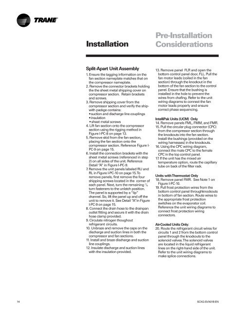
Split-Apart Unit Assembly<br />
1. Ensure the tagging information on the<br />
fan section nameplate matches that on<br />
the compressor nameplate.<br />
2. Remove the connector brackets holding<br />
the the sheet metal shipping cover on<br />
compressor section. Retain brackets<br />
<strong>and</strong> screws.<br />
3. Remove shipping cover from the<br />
compressor section <strong>and</strong> verify the shipwith<br />
packge contains:<br />
suction <strong>and</strong> discharge line couplings<br />
insulation<br />
sheet metal screws<br />
4. Lift fan section onto the compressor<br />
section using the rigging method in<br />
Figure I-PC-8 on page 13.<br />
5. Remove skid from the fan section,<br />
placing the fan section onto the<br />
compressor section. Reference Figure I-<br />
PC-9 on page 15.<br />
6. Install the connection brackets with the<br />
sheet metal screws (referenced in step<br />
2) on all sides of the unit. Reference<br />
Detail “A” in Figure I-PC-9.<br />
7. Remove the unit panels labeled RU <strong>and</strong><br />
RL in Figure I-PC-10 on page 15. To<br />
remove panels, first remove the four<br />
shipping screws located in the corner of<br />
each panel. Next, turn the remaining 1 /4<br />
turn fasteners to the unlatch position.<br />
The panel is supported by a “lip”<br />
channel. So, lift the panel up <strong>and</strong> off the<br />
unit to remove it. See Detail “A”in Figure<br />
I-PC-9 on page 15.<br />
8. Connect the drain hose to the drainpan<br />
outlet fitting <strong>and</strong> secure it with the drain<br />
hose clamp provided.<br />
9. Circulate nitrogen thoughout<br />
refrigerant circuits.<br />
10. Unbraze <strong>and</strong> remove the caps on the<br />
discharge <strong>and</strong> suction lines in both the<br />
compressor <strong>and</strong> fan sections.<br />
11. Install <strong>and</strong> braze discharge <strong>and</strong> suction<br />
line couplings.<br />
12. Insulate discharge <strong>and</strong> suction lines<br />
with the insulation provided.<br />
Pre-<strong>Installation</strong><br />
Considerations<br />
13. Remove panel FLR <strong>and</strong> open the<br />
bottom control panel door, FLL. Pull the<br />
fan motor leads (coiled in the fan<br />
section) through the knockout in the<br />
bottom of the fan section to the control<br />
panel. Ensure that the bushing is<br />
installed in the hole to prevent the<br />
wires from chafing. Refer to the unit<br />
wiring diagrams to connect the fan<br />
motor leads properly <strong>and</strong> ensure<br />
correct phase sequencing.<br />
IntelliPak Units (UCM) Only<br />
14. Remove panels FML, FMM, <strong>and</strong> FMR.<br />
15. Pull the circular plug connector (CPC)<br />
from the compressor section through<br />
the knockouts into the fan section.<br />
Install the bushings (provided on the<br />
wiring harnesses) in the knockouts.<br />
16. Using the CPC wiring diagram,<br />
connect the male CPC to the female<br />
CPC in the top control panel.<br />
17. If the unit has the mixed air<br />
temperature option, route the capillary<br />
tube on back of the filter rack.<br />
Units with Thermostat Only<br />
18. Remove panel FMR. See Note 1 on<br />
Figure I-PC-10.<br />
19. Pull frost protection wires from the<br />
bottom control panel throughknockouts<br />
in bottom of fan section. Route wires to<br />
the appropriate frost protection<br />
switches on the evaporator coil.<br />
Reference the unit wiring diagrams to<br />
connect frost protection wiring<br />
connectors.<br />
Air-Cooled Units Only:<br />
20. Route the refrigerant circuit wires for<br />
circuits 1 <strong>and</strong> 2 from the bottom control<br />
panel through the knockouts to the<br />
solenoid valves. The solenoid valves<br />
are located in the liquid refrigerant<br />
lines on the right-h<strong>and</strong> side of the unit.<br />
Refer to the unit wiring diagrams to<br />
make splice connections.<br />
14 SCXG-SVX01B-EN


