Installation, Owner, and Diagnostic Manual IntelliPak® - Trane
Installation, Owner, and Diagnostic Manual IntelliPak® - Trane
Installation, Owner, and Diagnostic Manual IntelliPak® - Trane

Create successful ePaper yourself
Turn your PDF publications into a flip-book with our unique Google optimized e-Paper software.
Skid Removal<br />
The unit ships on skids to provide forklift<br />
locations from the front or rear. The skid<br />
allows easy maneuverability of the unit<br />
during storage <strong>and</strong> transportation.<br />
Remove the skids before placing the unit<br />
in its permanent location.<br />
Remove the skids using a forklift or jack.<br />
Lift one end of the unit off of the skids.<br />
See Figure I-PC-5 <strong>and</strong> I-PC-6 on page 12<br />
for unit gravity block location. Slide the<br />
skids out <strong>and</strong> lower the unit at the<br />
installation location.<br />
Note: External isolation is not necessary<br />
since units are internally isolated. Consult a<br />
vibration specialist before “doubleisolating”<br />
the unit.<br />
External Unit Isolation<br />
If your job requires external vibration<br />
isolation, two options are available:<br />
isopads or spring-type isolators. Isopads<br />
should be placed under the unit at<br />
locations indicated on the factoryprovided<br />
isolator sheet.<br />
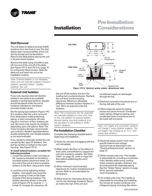
Set the spring-type isolators (Figure I-PC-<br />
9) in position after the unit is removed<br />
from skids before making electrical,<br />
piping, or duct connections. All units<br />
require a minimum of four isolators per<br />
unit. But some may require six isolators,<br />
depending upon unit options. Note: The<br />
<strong>Trane</strong> Company strongly recommends<br />
you consult a vibration specialist before<br />
double-isolating the unit. Double isolation<br />
is not recommended.<br />
If you decide to externally isolate the unit,<br />
use spring-flex, type CP isolators. The<br />
spring number is marked on the outer<br />
housing. See Figure I-PC-9.<br />
To install external isolators, complete the<br />
following procedure.<br />
1. Locate the isolators under unit base at<br />
the locations indicated on the factoryprovided<br />
isolator placement sheet. Lift<br />
one end of the unit at a time to position<br />
isolators to the floor, using anchor bolts.<br />
2. Level the unit by adjusting isolator<br />
heights. Unit weight may cause the<br />
upper housing to rest on the lower<br />
housing of the spring isolators. The<br />
isolator clearance shown in the side<br />
view of Figure I-PC-9, must be 1 /4 - 1 /2<br />
inches. To increase the clearance, lift<br />
<strong>Installation</strong><br />
the unit off the isolator <strong>and</strong> turn the<br />
leveling bolt counterclockwise. Recheck<br />
the unit level <strong>and</strong> the housing<br />
clearances. Maximum allowable<br />
difference between isolator heights is 1 /4<br />
inch. Shim as required under the<br />
isolators.<br />
Note: The compressors <strong>and</strong> fan assembly<br />
are internally isolated on most units. Due<br />
to this, the addition of external isolation<br />
devices (spring mounting isolators) is at<br />
the discretion of the building or HVAC<br />
system designer.<br />
Pre-<strong>Installation</strong> Checklist<br />
Complete the following checklist before<br />
beginning unit installation.<br />
o Verify the unit size <strong>and</strong> tagging with the<br />
unit nameplate.<br />
o Make certain the floor or foundation is<br />
level, solid, <strong>and</strong> sufficient to support the<br />
unit <strong>and</strong> accessory weights. See Table<br />
I-DW-1 on page 32. Level or repair the<br />
floor before positioning the unit if<br />
necessary.<br />
o Allow minimum recommended<br />
clearances for routine maintenance <strong>and</strong><br />
service. Refer to unit submittals for<br />
dimensions.<br />
o Allow three fan diameters above the<br />
unit for the discharge ductwork. Return<br />
air enters the rear of the unit <strong>and</strong><br />
Pre-<strong>Installation</strong><br />
Considerations<br />
Figure I-PC-9. Optional spring isolator dimensional data.<br />
conditioned supply air discharges<br />
through the top.<br />
o Electrical connection knockouts are on<br />
the top, left side of the unit.<br />
o Allow adequate space for piping<br />
access <strong>and</strong> panel removal. Condenser<br />
water piping, refrigerant piping, <strong>and</strong><br />
condensate drain connections are on<br />
the lower left end panel.<br />
Note: Unit height <strong>and</strong> connection locations<br />
will change if using vibration isolators. The<br />
unit height may increase up to 5 7 /8” with<br />
spring type isolators.<br />
o Electrical supply power must meet<br />
specific balance <strong>and</strong> voltage<br />
requirements as described in the<br />
“Electrical Requirements” section on<br />
page 37.<br />
o Water-cooled units only: The installer<br />
is responsible for providing a condenser<br />
main, st<strong>and</strong>by water pump, cooling<br />
tower, pressure gauges, strainers, <strong>and</strong><br />
all components for waterside piping.<br />
See the “Water Piping” section on page<br />
34 for general waterside<br />
recommendations.<br />
o Air-cooled units only: The installer is<br />
responsible for providing <strong>and</strong> installing<br />
the remote air-cooled condenser <strong>and</strong><br />
refrigerant piping, including filter driers.<br />
16 SCXG-SVX01B-EN