Installation, Owner, and Diagnostic Manual IntelliPak® - Trane
Installation, Owner, and Diagnostic Manual IntelliPak® - Trane
Installation, Owner, and Diagnostic Manual IntelliPak® - Trane

Create successful ePaper yourself
Turn your PDF publications into a flip-book with our unique Google optimized e-Paper software.
Model Number Description<br />
<strong>Installation</strong><br />
General<br />
Information<br />
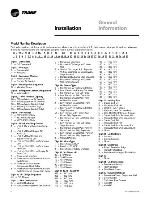
Each self-contained unit has a multiple character model number unique to that unit. To determine a unit’s specific options, reference<br />
the model number on the unit nameplate using the model number explanation below.<br />
S C W G N 20 4 2 BO A B 2 10 065 B A 1 0 1 0 A A C F A 1 1 0 T 2 0<br />
1 2 3 4 5 6 7 8 9 10 11 12 13 14 15 16 17 18 19 20 21 22 23 24 25 26 27 28 29 30 31 32 33 34 35 36<br />
Digit 1 - Unit Model<br />
S = Self Contained<br />
Digit 2 - Unit Type<br />
C = Commercial<br />
I = Industrial<br />
Digit 3 - Condenser Medium<br />
W = Water-Cooled<br />
R = Remote Air-Cooled<br />
Digit 4 - Development Sequence<br />
G = Modular Series<br />
Digit 5 - Refrigerant Circuit Configuration<br />
N = Independent<br />
Digit 6, 7 - Unit Nominal Capacity<br />
20 = 20 Tons (Water or Air Cooled)<br />
25 = 25 Tons (Water or Air Cooled)<br />
30 = 30 Tons (Water Cooled Only)<br />
32 = 32 Tons (Air Cooled Only)<br />
35 = 35 Tons (Water Cooled Only)<br />
Digit 8 - Unit Voltage<br />
6 = 200 Volt/60 Hz/3 ph<br />
4 = 460 Volt/60 Hz/3 ph<br />
5 = 575 Volt/60 Hz/3 ph<br />
Digit 9 - Air Volume/Temp Control<br />
1 = I-Pak & IGV <strong>and</strong> Supply Air Temp<br />
Ctrl<br />
2 = I-Pak & VFD <strong>and</strong> Supply Air<br />
Temp Ctrl<br />
3 = I-Pak & VFD w/ Bypass <strong>and</strong><br />
Supply Air Temp Ctrl<br />
4 = I-Pak w/o Vol. CTRL, w/ Zone Temp<br />
Cool<br />
5 = I-Pak w/o Vol. CTRL, w/ Zone Temp<br />
Heat/Cool<br />
6 = I-Pak w/o Vol. CTRL, w/ Supply Air<br />
Temp Ctrl<br />
8 = Thermostat Interface<br />
9 = Thermostat Interface w/Anti-Short<br />
Cycle Timer<br />
A = Thermostat Interface w/<br />
Compressor Start Delay<br />
B = Thermostat Interface w/Anti-Short<br />
Cycle Timer <strong>and</strong> Comp. Start Delay<br />
Digit 10, 11 - Design Sequence<br />
BO = “B” Design<br />
Digit 12 - Unit Construction<br />
A = Vertical Discharge<br />
B = Vertical Discharge with Double Wall<br />
C = Horizontal Discharge<br />
D = Horizontal Discharge w/ Double<br />
Wall<br />
E = Vertical Discharge, Ship Separate<br />
F = Vertical Discharge w/ Double Wall,<br />
Ship Separate<br />
G = Horizontal Discharge, Ship Separate<br />
H = Horizontal Discharge w/ Double<br />
Wall, Ship Separate<br />
Digit 13 - Plenum Type<br />
B = Std Plenum w/ Factory Cut Holes<br />
C = Low Plenum w/ Factory Cut Holes<br />
E = Std Plenum w/ Field Cut Holes<br />
F = Low Plenum w/ Field Cut Holes<br />
H = Std Plenum Double Wall (Perf)<br />
w/ Field Cut Holes<br />
J = Low Plenum Double Wall (Perf)<br />
w/ Field Cut Holes<br />
L = Std. Plenum w/Factory Cut Holes,<br />
Ship Separate<br />
M = Low Plenum with Factory Cut<br />
Holes, Ship Separate<br />
P = Std Plenum w/ Field Cut Holes, Ship<br />
Separate<br />
R = Low Plenum w/ Field Cut Holes,<br />
Ship Separate<br />
U = Std Plenum Double Wall (Perf) w/<br />
Field Cut Holes, Ship Separate<br />
V = Low Plenum Double Wall (Perf) w/<br />
Field Cut Holes, Ship Separate<br />
0 = Without Plenum<br />
Digit 14 - Motor Type<br />
1 = Std. Efficiency ODP<br />
2 = Premium Eff. ODP<br />
3 = Std. Efficiency Totally Enclosed<br />
Digit 15, 16 - Motor HP<br />
05 = 5 HP Motor<br />
07 = 7.5 HP Motor<br />
10 = 10 HP Motor<br />
15 = 15 HP Motor<br />
20 = 20 HP Motor<br />
25 = 25 HP Motor<br />
Digit 17, 18, 19 - Fan RPM<br />
085 = 850 rpm<br />
090 = 900 rpm<br />
095 = 950 rpm<br />
100 = 1000 rpm<br />
105 = 1050 rpm<br />
110 = 1100 rpm<br />
115 = 1150 rpm<br />
120 = 1200 rpm<br />
125 = 1250 rpm<br />
130 = 1300 rpm<br />
135 = 1350 rpm<br />
140 = 1400 rpm<br />
145 = 1450 rpm<br />
150 = 1500 rpm<br />
155 = 1550 rpm<br />
160 = 1600 rpm<br />
165 = 1650 rpm<br />
170 = 1700 rpm<br />
175 = 1750 rpm<br />
180 = 1800 rpm<br />
185 = 1850 rpm<br />
Digit 20 - Heating Type<br />
A = Steam Coil, LH<br />
B = Hot Water Coil, LH<br />
C = Electric Heat, 1 Stage<br />
F = Hydronic Heat Ctrl Interface<br />
G = Elec. Heat Ctrl Interface, 1 stage<br />
K = Steam Coil Ship Separate, LH<br />
L = Hot Water Coil Ship Separate, LH<br />
M = Steam Coil, RH<br />
N = Hot Water Coil, RH<br />
P = Steam Coil Ship Separate, RH<br />
R = Hot Water Coil Ship Separate, RH<br />
0 = None<br />
Digit 21 - Unit Isolators<br />
A = Isopads<br />
B = Spring Isolators<br />
0 = None<br />
Digit 22 - Unit Finish<br />
1 = Paint - Executive Beige<br />
2 = Protective Coating<br />
3 = Protective Coating w/ Finish Coat<br />
Digit 23<br />
0 = None<br />
Digit 24 - Unit Connection<br />
1 = Disconnect Switch<br />
2 = Terminal Block<br />
3 = Dual Point Power<br />
Digit 25 - Industrial Options<br />
A = Protective Coated Evaporator Coil<br />
B = Silver Solder<br />
C = Stainless Steel Screws<br />
D = A <strong>and</strong> B<br />
E = A <strong>and</strong> C<br />
6 SCXG-SVX01B-EN