Installation, Owner, and Diagnostic Manual IntelliPak® - Trane
Installation, Owner, and Diagnostic Manual IntelliPak® - Trane
Installation, Owner, and Diagnostic Manual IntelliPak® - Trane

Create successful ePaper yourself
Turn your PDF publications into a flip-book with our unique Google optimized e-Paper software.
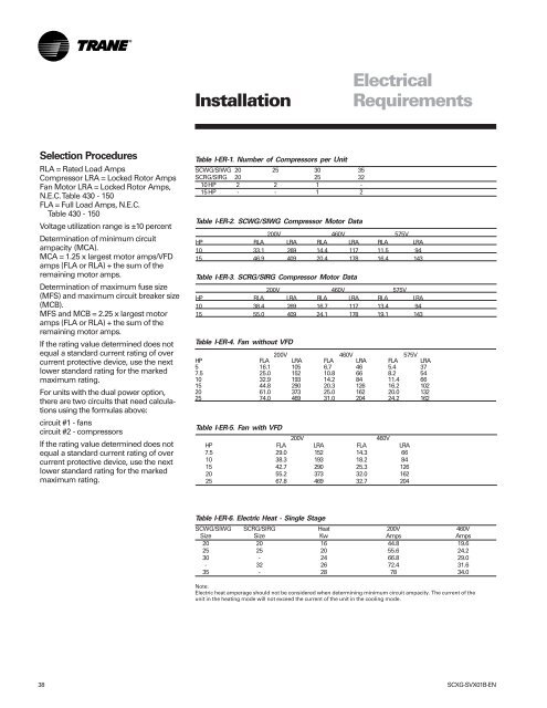
Selection Procedures<br />
RLA = Rated Load Amps<br />
Compressor LRA = Locked Rotor Amps<br />
Fan Motor LRA = Locked Rotor Amps,<br />
N.E.C. Table 430 - 150<br />
FLA = Full Load Amps, N.E.C.<br />
Table 430 - 150<br />
Voltage utilization range is ±10 percent<br />
Determination of minimum circuit<br />
ampacity (MCA).<br />
MCA = 1.25 x largest motor amps/VFD<br />
amps (FLA or RLA) + the sum of the<br />
remaining motor amps.<br />
Determination of maximum fuse size<br />
(MFS) <strong>and</strong> maximum circuit breaker size<br />
(MCB).<br />
MFS <strong>and</strong> MCB = 2.25 x largest motor<br />
amps (FLA or RLA) + the sum of the<br />
remaining motor amps.<br />
If the rating value determined does not<br />
equal a st<strong>and</strong>ard current rating of over<br />
current protective device, use the next<br />
lower st<strong>and</strong>ard rating for the marked<br />
maximum rating.<br />
For units with the dual power option,<br />
there are two circuits that need calculations<br />
using the formulas above:<br />
circuit #1 - fans<br />
circuit #2 - compressors<br />
If the rating value determined does not<br />
equal a st<strong>and</strong>ard current rating of over<br />
current protective device, use the next<br />
lower st<strong>and</strong>ard rating for the marked<br />
maximum rating.<br />
<strong>Installation</strong><br />
Table I-ER-1. Number of Compressors per Unit<br />
SCWG/SIWG 20 25 30 35<br />
SCRG/SIRG 20 25 32<br />
10 HP 2 2 1 -<br />
15 HP - - 1 2<br />
Table I-ER-2. SCWG/SIWG Compressor Motor Data<br />
Electrical<br />
Requirements<br />
200V 460V 575V<br />
HP RLA LRA RLA LRA RLA LRA<br />
10 33.1 269 14.4 117 11.5 94<br />
15 46.9 409 20.4 178 16.4 143<br />
Table I-ER-3. SCRG/SIRG Compressor Motor Data<br />
200V 460V 575V<br />
HP RLA LRA RLA LRA RLA LRA<br />
10 38.4 269 16.7 117 13.4 94<br />
15 55.0 409 24.1 178 19.1 143<br />
Table I-ER-4. Fan without VFD<br />
200V 460V 575V<br />
HP FLA LRA FLA LRA FLA LRA<br />
5 16.1 105 6.7 46 5.4 37<br />
7.5 25.0 152 10.8 66 8.2 54<br />
10 32.9 193 14.2 84 11.4 66<br />
15 44.8 290 20.3 126 16.2 102<br />
20 61.0 373 25.0 162 20.0 132<br />
25 74.0 469 31.0 204 24.2 162<br />
Table I-ER-5. Fan with VFD<br />
200V 460V<br />
HP FLA LRA FLA LRA<br />
7.5 29.0 152 14.3 66<br />
10 38.3 193 18.2 84<br />
15 42.7 290 25.3 126<br />
20 55.2 373 32.0 162<br />
25 67.8 469 32.7 204<br />
Table I-ER-6. Electric Heat - Single Stage<br />
SCWG/SIWG SCRG/SIRG Heat 200V 460V<br />
Size Size Kw Amps Amps<br />
20 20 16 44.8 19.6<br />
25 25 20 55.6 24.2<br />
30 - 24 66.8 29.0<br />
- 32 26 72.4 31.6<br />
35 - 28 78 34.0<br />
Note:<br />
Electric heat amperage should not be considered when determining minimum circuit ampacity. The current of the<br />
unit in the heating mode will not exceed the current of the unit in the cooling mode.<br />
38 SCXG-SVX01B-EN