- Page 1 and 2: Installation, Owner, and Diagnostic
- Page 3 and 4: Contents Cross reference to related
- Page 5 and 6: Installation Control Options Units
- Page 7 and 8: F = B and C G = A, B and C 0 = None
- Page 9 and 10: Receiving and Handling Shipping Pac
- Page 11 and 12: Installation Service Access See Fig
- Page 13 and 14: Rigging and Handling Unit Shipping
- Page 15 and 16: Figure I-PC-9 How to assemble the s
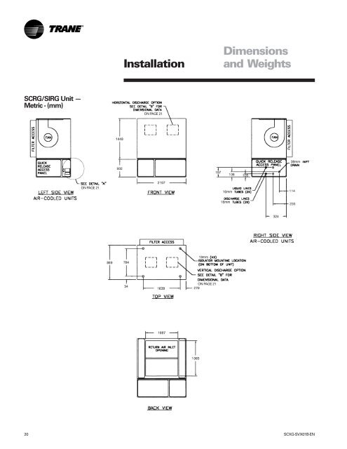
- Page 17 and 18: Installation Dimensions and Weights
- Page 19: SCRG/SIRG Unit — English - (inche
- Page 23 and 24: Steam Coil Steam Coil Dimensions -
- Page 25 and 26: Waterside Economizer Installation D
- Page 27 and 28: Detail “A” Detail “B” Dimen
- Page 29 and 30: Variable Frequency Drive with Bypas
- Page 31 and 32: Flexible Horizontal Discharge Plenu
- Page 33 and 34: Installation Duct Connections �
- Page 35 and 36: General Waterside Recommendations:
- Page 37 and 38: Installation Unit Wiring Diagrams S
- Page 39 and 40: Installation Figure I-PR-1. Supply
- Page 41 and 42: Installation Plenum Before installi
- Page 43 and 44: Waterside Economizer with Left-Hand
- Page 45 and 46: Installation Hydronic Coil Installa
- Page 47 and 48: Installation Variable Frequency Dri
- Page 49 and 50: Installation Static Pressure Transd
- Page 51 and 52: Standard with All Units Remote Zone
- Page 53 and 54: Figure I-PR-21. Standard zone senso
- Page 55 and 56: Programmable Night Setback Zone Sen
- Page 57 and 58: Figure I-PR-30. Grasslin time clock
- Page 59 and 60: Mounting the Remote Human Interface
- Page 61 and 62: Wiring the Remote Human Interface T
- Page 63 and 64: Installation Pre-Startup Checklist
- Page 65 and 66: BAYSENS020 BAYSENS020 Keypad and Di
- Page 67 and 68: Note: Blank temperature settings ma
- Page 69 and 70: Option Menu and Keypad Operation Th
- Page 71 and 72:
Installation Figure I-P-9. BAYSENS0
- Page 73 and 74:
Programming the Time Clock Option S
- Page 75 and 76:
Startup Log Complete this log at un
- Page 77 and 78:
Owner General Information Points Li
- Page 79 and 80:
Occupied/Unoccupied Contacts To pro
- Page 81 and 82:
VO relay - energized Exhaust fan (f
- Page 83 and 84:
Owner Table O-GI-6. GBAS Analog Inp
- Page 85 and 86:
condenser bypass valve closes, and
- Page 87 and 88:
mode at the HI panel. When in bypas
- Page 89 and 90:
Input Devices and System Functions
- Page 91 and 92:
Control Sequences of Operation Occu
- Page 93 and 94:
Occupied Sequence Of Operation All
- Page 95 and 96:
Compressors Units use two sizes of
- Page 97 and 98:
and according to the desired unit p
- Page 99 and 100:
Owner Maintenance Supply Fan Fan Dr
- Page 101 and 102:
Figure O-M-5. Fan assembly. Figure
- Page 103 and 104:
nitrogen into the system to raise t
- Page 105 and 106:
Owner Maintenance Figure O-M-7. Typ
- Page 107 and 108:
Coil Fin and External Cleaning Keep
- Page 109 and 110:
Owner Piping Components Water Valve
- Page 111 and 112:
System Checks Before proceeding wit
- Page 113 and 114:
Reset Required: (PAR) An automatic
- Page 115 and 116:
UCM’s Reaction: The system mode r
- Page 117 and 118:
ange for 10 continuous seconds, or
- Page 119 and 120:
Diagnostic Troubleshooting Diagnost
- Page 121 and 122:
Sensor Fail 113 Heat Module Comm Fa
- Page 123 and 124:
Water Temperature Requirements 35 W