Installation, Owner, and Diagnostic Manual IntelliPak® - Trane
Installation, Owner, and Diagnostic Manual IntelliPak® - Trane
Installation, Owner, and Diagnostic Manual IntelliPak® - Trane

Create successful ePaper yourself
Turn your PDF publications into a flip-book with our unique Google optimized e-Paper software.
Note: The compressors <strong>and</strong> fan assembly<br />
are internally isolated. Therefore, external<br />
isolation devices (spring mounting<br />
isolators) are at the discretion of a vibration<br />
specialist consulted by the building or<br />
HVAC system designer. In general, the<br />
<strong>Trane</strong> Company does not recommend<br />
double-isolation.<br />
<strong>Installation</strong><br />
Unit Vibration Isolator Option<br />
Vibration isolation is not necessary for the<br />
unit since the factory internally isolates<br />
the fan <strong>and</strong> compressors, thus creating<br />
double isolation. The <strong>Trane</strong> Company<br />
strongly recommends that you consult a<br />
vibration specialist when considering<br />
double isolation. If job requirements<br />
dictate unit isolators, use a housed-spring<br />
isolator with a locating pin. Factoryprovided<br />
unit isolators are type CP <strong>and</strong><br />
indicate the spring number on the outer<br />
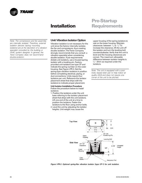
housing. See Figure I-PR-3. Set the<br />
spring-type vibration isolators in position<br />
before completing electrical, piping, or<br />
duct connections. Units require four<br />
isolators per unit. Reference the isolator<br />
placement sheet that ships with the<br />
isolators to indicate proper placement.<br />
Unit Isolator <strong>Installation</strong> Procedure<br />
Follow the procedure below to install<br />
isolators:<br />
1. Position the isolators under the unit<br />
base referring to the isolator placement<br />
sheet that ships with the unit isolators.<br />
Lift one end of the unit at a time to<br />
position the isolators. Fasten the<br />
isolators to the floor using anchor bolts.<br />
2. Level the unit by adjusting the isolator<br />
heights. Unit weight may cause the<br />
Pre-Startup<br />
Requirements<br />
upper housing of the spring isolators to<br />
rest on the lower housing. Maintain<br />
clearances between 1 /4 to 1 /2”. To<br />
increase the clearance, lift the unit off<br />
the isolator <strong>and</strong> turn the leveling bolt<br />
counterclockwise. Verify that the unit is<br />
level <strong>and</strong> the housing clearances are<br />
correct. The maximum allowable<br />
difference between isolator heights is<br />
1 /4”. Shim as required under the<br />
isolators.<br />
Note: The unit is equipped with a positively<br />
sloped drain pan to help indoor air<br />
quality (IAQ) <strong>and</strong> does not require one<br />
corner of the unit to be pitched.<br />
Figure I-PR-3. Optional spring-flex vibration isolator (type CP-1) for unit isolation.<br />
40 SCXG-SVX01B-EN