IFR VFR - MultiMania
IFR VFR - MultiMania
IFR VFR - MultiMania

You also want an ePaper? Increase the reach of your titles
YUMPU automatically turns print PDFs into web optimized ePapers that Google loves.
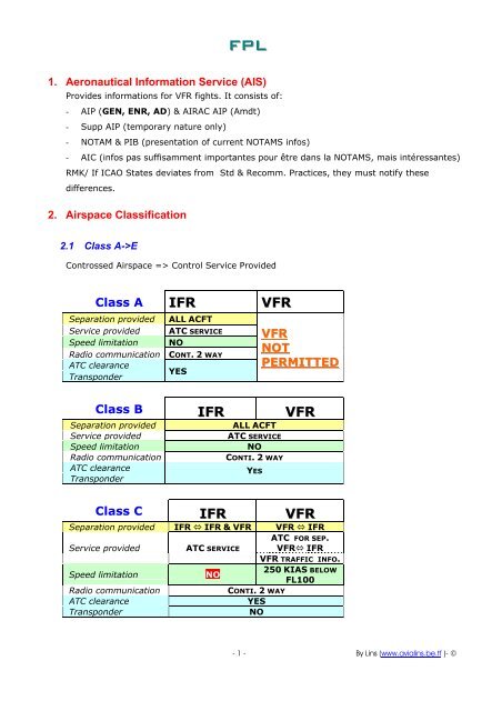
FPL<br />
1. Aeronautical Information Service (AIS)<br />
Provides informations for <strong>VFR</strong> fights. It consists of:<br />
- AIP (GEN, ENR, AD) & AIRAC AIP (Amdt)<br />
- Supp AIP (temporary nature only)<br />
- NOTAM & PIB (presentation of current NOTAMS infos)<br />
- AIC (infos pas suffisamment importantes pour être dans la NOTAMS, mais intéressantes)<br />
RMK/ If ICAO States deviates from Std & Recomm. Practices, they must notify these<br />
differences.<br />
2. Airspace Classification<br />
2.1 Class A->E<br />
Controssed Airspace => Control Service Provided<br />
Class A <strong>IFR</strong> <strong>VFR</strong><br />
Separation provided ALL ACFT<br />
Service provided ATC SERVICE<br />
Speed limitation NO<br />
Radio communication CONT. 2 WAY<br />
ATC clearance<br />
Transponder<br />
YES<br />
<strong>VFR</strong><br />
NOT<br />
PERMITTED D<br />
Class B <strong>IFR</strong> <strong>VFR</strong><br />
Separation provided ALL ACFT<br />
Service provided ATC SERVICE<br />
Speed limitation NO<br />
Radio communication CONTI. 2 WAY<br />
ATC clearance<br />
Transponder<br />
YES<br />
Class C <strong>IFR</strong> <strong>VFR</strong><br />
Separation provided <strong>IFR</strong> � <strong>IFR</strong> & <strong>VFR</strong> <strong>VFR</strong> � <strong>IFR</strong><br />
Service provided ATC SERVICE<br />
Speed limitation NO<br />
Radio communication CONTI. 2 WAY<br />
ATC clearance YES<br />
Transponder NO<br />
ATC FOR SEP.<br />
<strong>VFR</strong>� <strong>IFR</strong><br />
<strong>VFR</strong> TRAFFIC INFO.<br />
250 KIAS BELOW<br />
FL100<br />
- 1 - By Lins (www.avialins.be.tf )- ©
Class D <strong>IFR</strong> <strong>VFR</strong><br />
Separation provided <strong>IFR</strong> � <strong>IFR</strong> NO<br />
Service provided<br />
ATC + tfc info<br />
about <strong>VFR</strong> (+ tfc<br />
avoid. on<br />
request)<br />
Tfc info btwn<br />
<strong>VFR</strong> & <strong>IFR</strong><br />
(+ tfc avoid on<br />
request)<br />
Speed limitation 250 KIAS BELOW FL100<br />
Radio communication Conti. 2 way<br />
ATC clearance YES<br />
Transponder NO<br />
Class E <strong>IFR</strong> <strong>VFR</strong><br />
Separation provided <strong>IFR</strong> � <strong>IFR</strong> NO<br />
Service provided<br />
ATC + tfc info<br />
about <strong>VFR</strong> as<br />
practical<br />
Tfc info as<br />
practical<br />
Speed limitation 250 KIAS BELOW FL100<br />
Radio communication<br />
ATC clearance<br />
Cont. 2 way<br />
YES<br />
NO<br />
Transponder NO<br />
2.2 Class F & G<br />
Uncontrolled Airspace. Information Service Provided (Radar).<br />
RMK/ Class F is designated as Advisory Service.<br />
Class F <strong>IFR</strong> <strong>VFR</strong><br />
Separation provided<br />
<strong>IFR</strong> � <strong>IFR</strong> as<br />
practical<br />
NO<br />
Service provided<br />
ADVISORY<br />
SERVICE + FIS<br />
FIS<br />
Speed limitation 250 KIAS BELOW FL100<br />
Radio communication Cont. 2 way NO<br />
ATC clearance<br />
Transponder<br />
NO<br />
Class G <strong>IFR</strong> <strong>VFR</strong><br />
Separation provided NO<br />
Service provided FIS<br />
Speed limitation 250 KIAS BELOW FL100<br />
Radio communication Cont. 2 way NO<br />
ATC clearance<br />
Transponder<br />
NO<br />
- 2 - By Lins (www.avialins.be.tf )- ©
3. Section of Cruising Altitudes – VMC Minimas<br />
000/179 O D D<br />
E V E N 180/359<br />
<strong>IFR</strong> <strong>VFR</strong> Alt./FL <strong>IFR</strong> <strong>VFR</strong> Setting<br />
< 240 FL<br />
235 > FL<br />
230 > FL<br />
< 225 FL<br />
< 220 FL<br />
215 > FL<br />
210 > FL<br />
< 205 FL<br />
< 200 FL No <strong>VFR</strong> above FL200 unless ATC clearance<br />
195 > FL<br />
190 > FL<br />
< 185 FL<br />
< 180 FL<br />
175 > FL<br />
170 > FL<br />
< 165 FL<br />
< 160 FL<br />
155 > FL<br />
150 > FL<br />
< 145 FL<br />
< 140 FL<br />
135 > FL<br />
130 > FL<br />
< 125 FL<br />
< 120 FL<br />
115 > FL<br />
110 > FL<br />
< 105 FL<br />
< 100 FL<br />
95 > FL<br />
90 > FL<br />
< 85 FL<br />
< 80 FL<br />
75 > FL<br />
70 > FL<br />
< 65 FL<br />
< 60 FL<br />
55 > FL<br />
50 > Flight Level<br />
1013,2hPa<br />
< 4500 TA (Bel.) QNHloc QNHreg<br />
< 4000 QNHloc QNHreg<br />
3500 > QNHloc QNHreg<br />
3000 > QNHloc QNHreg<br />
< 2500 QNHloc QNHreg Free<br />
< F 2000 F QNHloc QNHreg Free<br />
R 1500 > R QNHloc QNHreg Free<br />
E 1000 > E QNHloc QNHreg Free<br />
E 500 E QNHloc QNHreg Free<br />
0 QNHloc QNHreg Free<br />
N<br />
N<br />
At & above FL100<br />
Vis. 8km<br />
Class B: CLR of Clouds<br />
Class C D E F G: 1000ft vertic.<br />
1500m horiz.<br />
Class B: CLR of Clouds<br />
Cl.C D E (+F&G above 3000ft<br />
MSL): 1000ft vertic.<br />
1500m horiz.<br />
C SEA C C <strong>IFR</strong> <strong>VFR</strong> EARTH<br />
Contr. Non-Contr<br />
Below FL100<br />
Vis. 5km<br />
Class F & G:<br />
At & Below 3000ft<br />
3000 ft AGL<br />
MSL ( 1000ft AGL)<br />
CLR of Clouds<br />
GND in Sight<br />
- 3 - By Lins (www.avialins.be.tf )- ©
3.1 RVSM<br />
000/179 O D D<br />
E V E N 180/359<br />
<strong>IFR</strong> <strong>VFR</strong> Alt./FL <strong>IFR</strong> <strong>VFR</strong> Setting VMC<br />
etc...500 > etc…<br />
495 FL<br />
490 > FL<br />
485 FL<br />
< 480 FL<br />
475 FL<br />
< 470 FL<br />
465 FL<br />
460 > FL<br />
455 FL<br />
450 > FL<br />
445 FL<br />
< 440 FL<br />
435 FL<br />
< 430 FL<br />
425 FL<br />
420 > FL<br />
415 FL<br />
INC LUS 410 > FL 410<br />
405 FL 405<br />
() FL 390<br />
385 FL 385<br />
( FL 380<br />
375 FL 375<br />
370 > FL 370<br />
365 FL 365<br />
() FL 350<br />
345 FL 345<br />
( FL 340<br />
335 FL 335<br />
330 > FL 330<br />
325 FL 325<br />
() FL 310<br />
305 FL 305<br />
( FL 300<br />
295 FL 295<br />
INC LUS 290 > FL 290<br />
Class B: CLR of Clouds<br />
Class C D E F G: 1000ft<br />
vertic.1500m horiz.<br />
At & above<br />
FL100<br />
RVSMTransitionNonRVSM<br />
< 285 FL No <strong>VFR</strong> levels above FL290<br />
< 280 FL <strong>VFR</strong> inactive in RVSM<br />
RMK/ Inside Non-RVSM areas, if <strong>VFR</strong> still exists, they takes <strong>IFR</strong> levels!<br />
- 4 - By Lins (www.avialins.be.tf )- ©
4. Aerodrome Criteria<br />
Control Zone Uncontrolled Zone<br />
Cloud Ceiling 1500ft 500ft<br />
GND visibility 5km 1,5km<br />
5. Low Flying – Minimum heights<br />
Cities<br />
<strong>VFR</strong> <strong>IFR</strong><br />
1000ft HGT 2000ft HGT above the<br />
above the<br />
highest obstacle<br />
highest obstacle within<br />
a radius of 8km<br />
within a radius<br />
of 600m<br />
Elsewhere 500ft HGT<br />
6. Usability of AD’s – Planning Minimas<br />
6.1 Suitable AD’s<br />
An AD is suitable if: - It is adequate (Rwy, IAPP,…)<br />
- Weater minimas are satisfied<br />
Airport Operating minima (APT.OPS.MIN)<br />
Considering: Wind, ACFT CAT, NOTAMS.<br />
Consist of: VIS/RVR, DA(H) or MDA.<br />
1000ft HGT above the<br />
highest obstacle within<br />
a radius of 8km<br />
Affected by: Crew qualifications, ACFT status, ACFT Category.<br />
Mountainous<br />
areas<br />
Elsewhere<br />
- 5 - By Lins (www.avialins.be.tf )- ©
6.2 Planning Minimas (Planning, In-Flight Re-Clearance and continuance of flight)<br />
Precision Approach(GS provided): minimum VIS/RVR. Eg. ILS, MLS, PAR<br />
Non-Precision Approach & Circling(No GS): minimum VIS/RVR && minimum ceiling. Eg.<br />
VOR, NDB.<br />
Rmk/ Planning Minimas must be fulfilled from ETA-1H -> ETA+1H.<br />
Type of approach on<br />
which APT.OPS.MIN<br />
are based<br />
PA<br />
Planning Minima Table<br />
PL.MIN.COL1 PL.MIN.COL2 PL.MIN.COL3 (VMC)<br />
Destination<br />
- with ALTN<br />
- via PP<br />
TO ALTN<br />
ERA in flight<br />
Destination ALTN<br />
ERA planned*<br />
Isolated APT Dest.<br />
CAT II/III RVR= RVR CATII/III RVR ≥ RVR CATI<br />
CAT I RVR= RVR CATI<br />
RVR ≥ RVR NPA<br />
&& Ceiling ≥ MDH NPA<br />
NPA<br />
RVR= RVR NPA<br />
&& Ceiling= MDH NPA<br />
RVR = RVR NPA+1000m<br />
&& Ceiling=MDH NPA+200ft<br />
Circling<br />
VIS=VIS Circling<br />
&& Ceiling ≥ MDH Circling<br />
6.2.1 RMK/ ERA ETOPS Planning Minima *<br />
Type of APP<br />
Dest. without ALTN<br />
DAPP<br />
PL.MIN.COL2 ” PL.MIN.COL2 ”<br />
AD with at least:<br />
2 Sep IAPP based on 2 Sep<br />
Aids serving 2SEP.RWYs<br />
MORE RESTRICTIVE<br />
Visibility ≥ 8km<br />
&&<br />
Cloud Base ≥ 1500ft<br />
AGL or MSA<br />
2 Sep IAPP based on 22 Sep Aids<br />
serving 1 RWY or<br />
1 IAPP based on 1 Aid serving 1 RWY<br />
2 RWY 1 RWY<br />
Precis. APP CAT II/III RVR ≥ RVR CAT I NPA<br />
Precis. APP CAT I<br />
RVR ≥ RVR NPA<br />
&& Ceiling ≥ MDH NPA<br />
Circling or (if not available)<br />
NPA +1000m/+200ft<br />
Lower of (lower restrictive)<br />
Higher of<br />
NPA<br />
NPA +1000m/+200ft or NPA +1000m/+200ft or<br />
Circling minima<br />
Circling minima<br />
Circling APP Circling minima<br />
RMK/ When Dest. is isolated (no ALTN within a suitable range) => The Holding Reserve shall not<br />
be less than required to hold for 2 hours at the AUW (JET).<br />
RMK/ VIS is sometimes used in place of RVR but have a different meaning:<br />
- VIS is measured by a human person (how many RWY lights can I see?)<br />
- RVR is measured by a machine<br />
- 6 - By Lins (www.avialins.be.tf )- ©
6.3 TO ALTN* (1#out**): should be located within – cf. PLMIN.COL1<br />
6.3.1 2 # ACFTs:<br />
- 1h flight time with 1# out cruising speed (cf. AFM) ISA cond. based on the actual TOW, or<br />
- For ACFT & Crew authorized for ETOPS: 2h flight time or ETOPS diversion time (if less), at<br />
the 1# out cruising speed.<br />
6.3.2 3 & 4 # ACFTs<br />
2h flight time with 1# out cruising speed (cf. AFM) based on the actual TOW.<br />
*TO ALTN is required if not possible to go back to departure AD (MTO or Perfos. reasons).<br />
** Logical… if we go to the TO ALTN 1#out is the most probable reason.<br />
6.4 Dest & Dest ALTN (<strong>IFR</strong>) – cf. PL.MIN.COL1 & 2<br />
At least 1 Dest ALTN unless:<br />
� Duration of flight ≤ 6h &&<br />
� at least 2SEP.RWY && Dest. with no ALTN<br />
� MTO ETA-1H -> ETA+1H: PL.MIN.COL3 (VMC) ; Or (PL.MIN.COL.3)<br />
Destination is isolated (no alternate in the vicinity) – PL.MIN.COL2<br />
2 Dest ALTN are required when<br />
� MTO ETA-1H -> ETA+1H at Dest ≤ PL.MIN.COL1 or<br />
� No Weather info available<br />
6.5 En-Route Alternates ERA – cf. PL.MIN.COL1 & 2<br />
An ERA is an APT within a reasonable distance of the planned route that can be used to<br />
reduce Contingency Fuel below the usual requirement of 5% of the Trip Fuel(->3%).<br />
ERA should be located in a circle having a radius = 20% Trip Distance. The center of this<br />
circle lies on the planned route at a distance from the destination:<br />
= 25% Trip Distance, or<br />
= 20% Trip Distance + 50NM, whichever is greater.<br />
RMK/ ERA can never be farther than the planned destination.<br />
RMK/ Separate Rwys ‘2SEP.RWY’: (JAR-OPS)<br />
� Separate LDG SFC, such that if one is blocked, it will not prevent the operations on the<br />
other, &&<br />
� Each of the LDG SFC has a separate IAPP based on separate Aids.<br />
- 7 - By Lins (www.avialins.be.tf )- ©
6.6 Synthesis<br />
Type of FP<br />
CONDITION REQUIRED for<br />
Planning or<br />
In-Flight Re-Planing<br />
Dest with 1 ALTN ALTN Dest ≥ PL.MIN.COL1 &&<br />
DEP<br />
1 ALTN ≥ PL.MIN.COL2 &&<br />
DEST ERA ≥ PL.MIN.COL2<br />
Dest with 2 ALTN<br />
(if Dest ≤ PL.MIN.COL1 or 2 ALTN ≥ PL.MIN.COL2 &&<br />
No Weather info available) ERA ≥ PL.MIN.COL2<br />
DP Procedure<br />
At Planning:<br />
ID ≥ PL.MIN.COL1 &&<br />
IA ≥ PL.MIN.COL2 &&<br />
ID IA<br />
ERA ≥ PL.MIN.COL2<br />
At DP:<br />
DEP<br />
RD ≥ PL.MIN.COL1 &&<br />
DP RD RA RA ≥ PL.MIN.COL2<br />
ERA ≥ PL.MIN.COL2<br />
PP Proedure<br />
At Planning:<br />
ALTN<br />
Dest ≥ PL.MIN.COL1 &&<br />
ALTN ≥ PL.MIN.COL2 &&<br />
ERA ≥ PL.MIN.COL2<br />
DEP PP DEST At PP:<br />
Dest choosen ≥ PL.MIN.COL1<br />
No ALTN<br />
Dest ≥ PL.MIN.COL3 &&<br />
Flight Time ≤ 6h &&<br />
DEP DEST<br />
2SEP.RWYs &&<br />
ERA ≥ PL.MIN.COL2<br />
Isolated APT Dest ≥ PL.MIN.COL2 &&<br />
ERA ≥ PL.MIN.COL2<br />
Continuance of Flight<br />
Dest ≥ PL.MIN.COL1<br />
Or<br />
1 ALTN ≥ PL.MIN.COL2 &&<br />
ERA* ≥ PL.MIN.COL1<br />
* ERA in flight !<br />
Dest ≥ PL.MIN.COL1 &&<br />
ERA ≥ PL.MIN.COL1<br />
Dest ≥ PL.MIN.COL1 &&<br />
ERA ≥ PL.MIN.COL2<br />
DP: Decision Point (Over DP, ACFT is re-cleared to a new destination with alternate)<br />
ID: Initial Destination<br />
IA: Initial Alternate<br />
RD: Re-Cleared Destination<br />
RA: Re-Cleared Alternate<br />
PP: Predetermined Point (Over PP, ACFT becomes commited to either the Dest. or the ALTN<br />
6.7 Fuel Policy<br />
6.7.1 Minimum Fuel:<br />
DP Procedure: 1 + 2 + 3i + 4 + 5 + 6a (+7)<br />
ISOL.AD Procedure: 1 + 2 + 3 + 5 +6b (+7)<br />
PP Procedure: 1 + 2* + 3 + 5 + 6b (+7)<br />
* the greater of : DEP-PP-DEST or DE-PP-ALTN fuel<br />
- 8 - By Lins (www.avialins.be.tf )- ©
R<br />
E<br />
S<br />
E<br />
R<br />
V<br />
E<br />
F<br />
U<br />
E<br />
L<br />
6.7.2 JAR-OPS<br />
1) TAXI FUEL: Prior to TO. (+APU consumption)<br />
2) TRIP FUEL: - TO & Climb Fuel to initial Cruising Level (take account SID routing)<br />
(TF) - Fuel from TOC to TOD = Cruise(including Step Climb & Step Descent)<br />
- Fuel from TOD to Approach (take account STAR routing)<br />
- Fuel for Approach & Landing<br />
3) CONTINGENCY FUEL: higher of a) or b) (Conti)<br />
a) either:<br />
i- 5% TRIP FUEL (|| if replanning, 5% remainder of flight); or<br />
ii- No less than 3% TRIP FUEL (|| if replanning, 3% remainder of flight), if<br />
en-route alternate (ERA)(1) is available; or<br />
iii- Fuel to fly 20 min. En-Route (based upon the Trip Fuel Consumption); or<br />
iv- Fuel to fly 15 min. at 1500ft above destination.<br />
b) In booth case, shall not be less than Fuel to fly 5 min. at 1500ft above<br />
destination (STD Cond).<br />
4) ALTERNATE FUEL: - Missed Approach Fuel: from MDA (non-precision) or DH (precision)<br />
(ALTN Fuel) to the Missed Approach Altitude.<br />
- Fuel to Climb from Missed Approach Altitude to Cruising Level.<br />
- Fuel from TOC to TOD (Long Range Cruise)<br />
- Fuel from TOD to Approach (take account STAR routing)<br />
- Fuel for Approach & Landing<br />
RMK/ if 2 destination alternates are required, alternate fuel should be sufficient to proceed<br />
to the alternates which requires the greater amount of fuel.<br />
5) FINAL RESERVE FUEL1: - Fuel to fly 45 min. at 1500ft. above destination (PROP)<br />
(FRF) - “ 30 min “ “ (JET)<br />
… in STD conditions, and the lower of Best Eco. or Long Range consumption…<br />
6) MINIMUM ADDITIONAL FUEL*: should permit: except Concorde!<br />
a) - in the event of 1# out or pressurisation failure occuring at the most critical point:<br />
• Fuel to descent (as required) and joint adequate AD; and<br />
• Fuel for 15 min. hold at 1500ft above alternate AD, in STD conditions; and<br />
• Fuel for approach and Landing.<br />
- For <strong>IFR</strong> without Dest ALTN, fuel for 15 min. holding at 1500ft above destination, under<br />
STD conditions; and<br />
b) For isolated AD, fuel to fly (ISOL.AD Fuel)<br />
- 2hrs (normal cruise consumption) overhead Dest (JET).<br />
- 45min+15% Flight Time Planned at cruise level or 2hrs if less (PROP).<br />
* Only if fuel from 2->5 is not sufficient to do this.<br />
7) EXTRA FUEL: at the discretion of the commander.<br />
(1)<br />
ERA should be located in a circle having a radius = 20% Trip Distance.The center of this circle lies on the planned route at a distance<br />
from the destination: = 25% Trip Distance, or<br />
= 20% Trip Distance + 50NM, whichever is greater.<br />
- 9 - By Lins (www.avialins.be.tf )- ©
1<br />
2<br />
DEP DEST ALTN<br />
Taxi Acc+TO Climb Cruise Descent IAPP MisAPP LONG RANGE IAPP&LDG HLD1<br />
7. Fuel & Oil Supply<br />
7.1 Propellers ACFTs (Jets)<br />
7.1.1 Dest ALTN Required<br />
TF + ALTN Fuel + FRF (+ Conti)<br />
or<br />
Fuel[Dep->PP->ALTN] + FRF (+ Conti) || TF + ISOL.AD Fuel (if greater)<br />
7.1.2 Dest ALTN not Required<br />
TF(VMC App) + FRF (+ Conti) or TF + ISOL.AD Fuel<br />
8. Approach Charts<br />
Chart Index Number:<br />
10-3<br />
First Digit: APT number (if more than one APT per city)<br />
Second Digit: Type of chart 0 – Area, SID, STAR…<br />
1 – ILS, MLS,…<br />
2 – GPS<br />
3 – VOR<br />
4 – TACAN (DME)<br />
5 – /<br />
6 – NDB<br />
7 – DF<br />
8 – Radar<br />
9 – <strong>VFR</strong><br />
Third Digit: Filing order. ( 10-2: STAR, 10-3: SID, etc…)<br />
8.1 SIDs -> Obstacle Clearance Minimas<br />
3<br />
Based on the ACFT crossing the end of RWY at 35ft or higher and climbing at 200ft/NM to<br />
400ft above AD before turning.<br />
- 10 - By Lins (www.avialins.be.tf )- ©<br />
4<br />
5
200ft<br />
400ft<br />
152ft 304ft<br />
35ft Min<br />
0NM 1NM 2NM<br />
3.3% GoC or otherwise published<br />
2.5% GoC : Slope assessed for obstacles<br />
Any obstacle penetrate this slope are published + obstacle<br />
avoidance Procedure.<br />
RMK: Go-Around GoC: 2,5%<br />
200/6080=3,3%<br />
3.3% GoC => 200ft/NM (ACFT) Provides a minimum of 48ft obstacles<br />
clearance for each NM of flight.<br />
2.5% GoC => 152ft/NM (obstacles)<br />
(Margin : 0.8%)<br />
9. Selection of Altitudes and Routes<br />
9.1 Temperature correction<br />
If T° are below ISA-15:<br />
Surface Temp. MOCA/MORA Correction<br />
ISA-16 -> ISA-30°c +10%<br />
ISA-31 -> ISA-50°c +20%<br />
ISA-51 -> below +25%<br />
9.2 Wind Correction<br />
When operating within 20NM of terrain whose max. elev. >2000ft:<br />
Terrain<br />
Wind Speed [kts]<br />
Elevation 0-30 31-50 51-70 71-…<br />
2000-8000ft +500ft +1000ft +1500ft +2000ft<br />
8001-above +1000ft +1500ft +2000ft +2500ft<br />
9.3 Approach Altitude Correction -> True Altitude<br />
AD Temp<br />
1500 (OM)<br />
Height above AD (ft)<br />
2000 (intercept GS) 3000 (intercept GS)<br />
0 +60ft +80ft +140ft<br />
-10 120 160 260<br />
-20 180 240 380<br />
-30 240 320 500<br />
Values to be added to the published altitudes.<br />
RMK/ T°>>TISA -> True Alti> Alti indiquée => moins grave…<br />
9.4 MEA Min. Safe En-Route Altitude (<strong>IFR</strong>)<br />
MEA is the lowest published Altitude between radio fixes that meets obstacle clearence<br />
requirements and assures acceptable navigation signal coverage.<br />
MEA applies to the entire width of the AWY defined between those radio fixes.<br />
RMK/ MRA: min. reception altitude…<br />
- 11 - By Lins (www.avialins.be.tf )- ©
9.4.1 Calculation of MEA:<br />
9.4.1.1 Elevation of the highest point plus:<br />
Elev. Of the highest point Increment<br />
≤ 5000ft 1500ft<br />
5001 ≤ Elev. ≤ 10000ft 2000ft<br />
≥ 10001ft 10% Elev. + 1000ft<br />
RMK/ For last route segment ending over the IAF, a reduction to 1000ft is permissible within TMAs<br />
where a higher degree of nav accuracy is ensured.<br />
The values are rounded to the next 100ft.<br />
9.4.1.2 Distance covered on either side of the TRK:<br />
Segment length ≤ 100NM<br />
10 NM (may be reduce to 5NM if high degree of nav. Accuracy)<br />
Segment length ≥ 101NM<br />
10% of the segment length (with a max. of 60NM)<br />
9.5 MOCA Min. Obstruction Clearance Altitude<br />
MOCA is the lowest published Altitude between radio fixes that meets obstacle clearence<br />
requirements (only!) for the entire route segment (always lower than MEA).<br />
� MOCA is the sum of:<br />
Elev. or obstacles ≤ 6000ft + 1000ft<br />
Elev. or obstacles ≥ 6001ft + 2000ft<br />
COBIA CASIL<br />
5000-3800T<br />
MEA MOCA<br />
9.5.1 Lateral Area Coverage<br />
9.5.1.1 From a VOR Station<br />
VOR 1ONM 20NM 40NM (Max Width)<br />
70NM<br />
140NM<br />
280NM<br />
- 12 - By Lins (www.avialins.be.tf )- ©
9.5.1.2 From an NDB Station<br />
NDB 1ONM 20NM 60NM (Max Width)<br />
40NM<br />
80NM<br />
245NM<br />
9.6 MORA Min. Off Route Altitude (Jeppesen)<br />
9.6.1 Route MORA<br />
This notion, derived by Jeppesen provides known obstruction clearance within 10NM of the<br />
route centerline, including around radio fix reporting points.<br />
� Route MORA is the sum of:<br />
Elev. or obstacles ≤ 5000ft + 1000ft<br />
Elev. or obstacles ≥ 5001ft + 2000ft<br />
RMK/ A Route MORA is not always depicted on the chart, but its value can be determined by the<br />
highest value of the Grid MORA along the route.<br />
RMK/ MFA (Min Flight Altitude) ~Route MORA pour des segments très longs sans NavAid entre les<br />
2 VOR<br />
9.6.2 Grid MORA<br />
This notion, derived by Jeppesen provides known obstruction clearance within each grid<br />
formed by charted lines of latitude and longitude in consideration.<br />
� Grid MORA is the sum of:<br />
Elev. or obstacles ≤ 5000ft + 1000ft<br />
Elev. or obstacles ≥ 5001ft + 2000ft<br />
1 5<br />
=>1500ft<br />
RMK/ When planning a <strong>VFR</strong> route, it is recommended to use this safety altitude.<br />
- 13 - By Lins (www.avialins.be.tf )- ©
9.7 MSA (Minimum Safe/Sector Altitude)<br />
Cf. IAPP charts. It’s a minimum safe altitude which provides 1000ft obstacle clearance<br />
within 25NM radius from the indicated Nav Aid on which it is centered.<br />
This altitude is FOR EMERGENCY USE ONLY, and does not necessary guarantee navaid<br />
reception. If the M Safe A is divided into sectors -> Minimum Sector Altitude.<br />
5700’ 5000’<br />
4000’<br />
9.8 MAA - Max Authorised Altitude<br />
Ex.: MAA7000<br />
9.9 MDA – Min. Descent Altitude<br />
Lowest Altitude (AMSL) to which descent is authorised on NPA ( GS out) without field in<br />
sight. Missed Approach must be initiated at the MAP (Missed Approach Point) ‘M’.<br />
9.10 DA – Decision Altitude<br />
Same as MDA, but for PA (Precision App) -> Missed App Procedure must be initiated.<br />
9.11 MCA – Minimum Crossing Altitude<br />
9.12 MHA – Minimum Holding Altitude & MAX Hold Alt (eg. MAXFL120)<br />
MHA<br />
MEA<br />
- 14 - By Lins (www.avialins.be.tf )- ©
10. Doc 8168 PANS-OPS<br />
RMK/ - Bank Angle: 25° or Rate 1 (360°/2min or 3°/sec) whichever is less.<br />
- Maltese Cross: FAF (Final Approach Fix) !!! … cf Fred exam OPS<br />
- Descent on the GP must not ne commenced until the ACFT is establshed within ½ scale<br />
deflection of the LOC.<br />
- OM: 1500ft<br />
10.1 Holding Pattern<br />
//<br />
10.2 Procedure Turn<br />
Used for NPA!<br />
10.3 Base Turn<br />
1, 2 & 3 min.<br />
D<br />
Outbound Track (1 min)<br />
30°<br />
A compl<br />
- 15 - By Lins (www.avialins.be.tf )- ©
11. NAT – North Atlantic Track System<br />
Height Band : 310-390… à vérif<br />
000/179 O D D<br />
E V E N 180/359<br />
<strong>IFR</strong> <strong>VFR</strong> Alt./FL <strong>IFR</strong> <strong>VFR</strong> Setting<br />
etc…<br />
450 > FL<br />
445 FL<br />
440 FL<br />
435 FL<br />
< 430 FL<br />
425 FL<br />
420 FL<br />
415 FL RVSM non RVSM<br />
INC LUS 410 > FL 410<br />
405 FL 405<br />
() FL 390<br />
385 FL 385<br />
( FL 370<br />
365 FL 365<br />
() FL 350<br />
345 FL 345<br />
( FL 330<br />
325 FL 325<br />
() FL 310<br />
305 FL 305<br />
( FL 290<br />
285 FL<br />
< 280 FL<br />
275<br />
270 ><br />
265<br />
< 260 At or Above FL 60<br />
255 (or 2000ft if higher)<br />
…<br />
etc… CLASS A<br />
95<br />
90 > (no <strong>VFR</strong>)<br />
85<br />
< 80<br />
75<br />
70 ><br />
65<br />
< 60<br />
55 > Below FL 60<br />
50 > CLASS G<br />
< etc…<br />
- 16 -
The NAT Region:<br />
Comprise some FIRs (Bodo, Reykjavic,…) which are high sea airspace & the Concil of ICAO<br />
has resolved rules appropriate but responsibility for enforcement of them rests with the<br />
ACFT State of Registry.<br />
Air Routes within MNPS:<br />
OTS (Organised Track Systems) are published daily for the East & the Westbound flows.<br />
RMK/ Flights partially outside OTS should be planned along Great Circle Track (ORTHO) E-W or N-S<br />
FPL & ATC Reports within MNPS:<br />
E-W: -> south of 70°N: Par 10° de long from Greenwich<br />
-> north of 70°N: Par 20° de long from Greenwich<br />
Dist btwn signif pts should not exceed 1hr Flt Time<br />
N-S: 5° lat intervals<br />
Content of Report: Position (E-W: Lat ° & ‘ Lon °; N-S: Lat ° Lon ° & ’) + Time (4 digits)<br />
Adjascent OCA (boudary less 60NM): ACFT should report position on booth OCAs<br />
NAT - MNPS Approval:<br />
FPL Item 10 EQUIPMENT . S / X if approved MNPS or . S / W if approved RVSM.<br />
Submission:<br />
NAT & ATFM: 3hrs<br />
Nav Perfo Accuracy:<br />
Lateral Trk Error: must read back all the clearance specified in the FPL<br />
Any change of 3’ of ETA for entering oeanic region must be informed to ATC.<br />
- 17 -
OTS:<br />
2 flows: Europe Westbound Morning Departure (peak: 11:30 ->18:00)<br />
North-America Eastbound Evening Departure (peak: 01:00 ->08:00)<br />
… at 30°W (timing reference for OTS/MNPS)<br />
Changeover period: to ensure smooth day/night transition -> btwn 08:01->11:29 & btwn 18:01 -> 00:59.<br />
Use of RVSM & Mach Number technique.<br />
System is constructed every 12 hours by the OAC (Oceanic Area Ctl center):<br />
The agreed OTS is then promulgated as the “NAT Track Message” via an AFTN (Aero Fix<br />
Telecom Network)<br />
RMK/ OTS are NOT mandatory!!<br />
NAT TRK MSG:<br />
� Full details of OTS (coord, FL expected, entery…)<br />
Day-time: The most northerly TRK: A – then: B - …<br />
Night-time: The most southerly TRK: Z – then: Y - …<br />
Ex: Day-Time OTS Westbound 1130UTC – 1800UTC at 030°W<br />
RMK/ OCA planners can take account of Operators’ prefered routes => Prefered Route Msg PRM<br />
PTS (Polar TRK Structure):<br />
Consist of 10 fixed TRK in Reykjavick & 5 fixed TRK in Bodo OCA<br />
FPL: Item 15 (route) “PTS + trk nbr” (Other Flt must specify full trk).<br />
Each pt where M or FL change is planned must be specified as “Lat & Long” fallowed by<br />
“PTS + trk code nbr”.<br />
Abbreviated Clearances:<br />
Must read back the Msg & full details of the TRK specified by the ‘trk code nbr’.<br />
Abbreviated Position Reports:<br />
By replacing the normal “lat long” report with the word “Polar + trk code nbr”. Normally<br />
made at the significant pts of the PTS trk<br />
RMK/ NAT: surface horizontale (plusieurs FIR)<br />
MNPS : Volume d’air vertical (FL290�FL410)<br />
12. Mean Wind Component & Mean Fuel Flow Calculation<br />
MeanComponent<br />
=<br />
∑<br />
FactoredCompoment<br />
TotalTime<br />
FactoredComponent=Time[hrs]*Component<br />
Recall: FF=f(Alti, T, Pwr)<br />
13. Fuel Efficiency Calculations<br />
Fuel burned per unit distance flown over ground: Gross Fuel Flow (GFF)<br />
GS<br />
FF GFF=<br />
- 18 -
14. METEOROLOGY SERVICES FOR AVIATION<br />
14.1 SIGMET<br />
Issued by meteorological watch service if weather phenomena may affect safety of flight:<br />
- Thunderstorms TS (FRQ, SQL, EMBD, OBSC);<br />
- Cyclone (TC+name);<br />
- Freezing rain (FZRA);<br />
- Heavy Hail (HVYGR);<br />
- Severe Turbulence (SEV TURB);<br />
- Severe Aiframe Icing (SEV ICE);<br />
- Severe Mountain (standing) waves (SEV MTW)<br />
- Heavy Sand/Dust Storm (HVY SS/DS)<br />
- Volcanic Ash (VA+ Volcan name)<br />
They’re transmitted to ACFT via ATC.<br />
Validity: 4hrs (except for volcanic ash: 12hrs)<br />
Eg. “WSUK310630 EGTT SIGMET NO 03 VALID 310630/311030 EGRR-LONDON FIR SEV<br />
MTW VSP 650FPM FCST FL070/120 NW OF LINE 52N 06W TO 51N 01E TO 55N 01E MOV E<br />
20KT NC=”<br />
(no change…)<br />
14.2 ACFT observations & reports<br />
14.2.1 ASDAR<br />
ACFT to Satellite Data Relay. Every 7 minutes.<br />
14.2.2 AIREP (Voice)<br />
If required, they are normally separated by 1hr.<br />
S<br />
E<br />
C<br />
T.<br />
1 Ident<br />
2 Position<br />
3 Time<br />
4 FL<br />
5 Next Pos & ETO<br />
1 6 Next Signif. Pt<br />
S. 7 ETA<br />
2 8 Endurance<br />
9 T<br />
S 10 W<br />
E 11 V<br />
C 12 CAT<br />
T. 13 ICING<br />
3 14 Humidity<br />
15 Suppl. Info.<br />
- 19 -
14.2.3 Windshear Reporting<br />
14.2.4 Reporting CAT<br />
High Level Turbulence (>15000ft) not associated with Cb should be reported as CAT.<br />
Incidence:<br />
- Occasional (2/3 of time)<br />
- Continous (>2/3 of time)<br />
Intensity:<br />
- Light (IAS fluctuate by 5-15 kts)<br />
- Moderate (IAS fluctuate by 15-25 kts)<br />
- Severe (IAS fluctuate by more than 25 kts)<br />
14.2.5 Reporting Airframe Icing<br />
Intensity:<br />
- Trace (preceptible)<br />
- Light (problems if flight exceed 1h, except if anti/de-ice used)<br />
- Moderate (anti/de-ice necessary!)<br />
- Severe (Rate of accumulation>> . Diversion if necessary)<br />
- 20 -
14.3 Infos to ACFT in flight<br />
14.3.1 VOLMET<br />
14.3.2 ATIS<br />
14.4 METAR (MEteo AeRodrome)<br />
Observed each 10’… published each 30’ (if no significant changes)<br />
Actual Weather conditions observed at AD.<br />
Eg. “SABX310850 EBBR 310850Z …”<br />
TREND: Short-term landing forecast (or significant change), during the 2hrs fallowing the<br />
time of the METAR. BCMG or TEMPO «moins de 1h dans les 2 prochaines h» (… FM … TL), or NOSIG.<br />
NOSIG: No Significan Change or forecast for the next 2hrs. (=NSC cf TAFs)<br />
(NSW: No Significant Weather… cf TAFs)<br />
RMK/ Significant Weather: RA, BR, FG,…<br />
CAVOK: RVR, weather & cloud are replaced by CAVOK if:<br />
- Vis > 10km<br />
- No cloud below 5000ft or below MSA if greater && No Cb,<br />
- No precipitation or fog<br />
SNOWTAM: Group of 8 digits ‘lost’ in the METAR:<br />
Eg: 25290066<br />
� 25/2/9/00/66<br />
RWY/TypeOfContaminant/%RWYcontaminated/Depth/BA<br />
Eg: RWY06 ICE 0-10 PCT1MM BA50=<br />
B.A (Snowtam)Code<br />
Good (9)5 or 40 (0.40)<br />
TO/LDG within sched wet dist<br />
Medium/Good 94<br />
Medium 93 All wet sched dist + safety factor<br />
Medium/Poor 92<br />
Poor 91 or 25 (0.25)<br />
At least Full aquaplaning distance<br />
Unreliable 99<br />
RMK/ Water Equivalent depth:<br />
Type SG Max Depth (mm) WED=SG.Depth<br />
Very Dry Snow VDS 0.5<br />
Compact Snow CS >0.5<br />
15<br />
Slush Sl 0.5 -> 0.8<br />
Standing Water Wat 1<br />
Supplement Info: RE (recent weather) observed in the last hour or WS (windshear).<br />
- 21 -
14.5 SPECI<br />
If significant change of W/V ; Vis/RVR ; Weather, Ceiling, QNH,…<br />
“SPECIal report” is a METAR intercalled between two ‘normal’ METARs if significant change<br />
occurs (W/V, Vis, RVR, QNH,…)<br />
Eg. “SPBX310910 EBFS 27014KT 9999 FEW012 SCT016 BKN130 15/11 Q1018=”<br />
14.6 TAF<br />
Terminal AD Forecast normally cover a forecast period of from 9 to 24hrs and are updated<br />
every 3hrs(TAF ->12h) & 6h (TAF ->24h).<br />
No QNH , T/Td & RVR in TAFs.<br />
TEMPO: less than 1hrs between the given period. Eg. “TEMPO 1316”.<br />
Eg. “FCBX310900 EBBR 310850Z 311019 …”<br />
- 22 -
15. Charts<br />
15.1 Low Level Forecast Tabular<br />
SFC->10.000ft (wind for 2000, 5000 & 10.000ft)<br />
15.2 Medium/High Level Forecast Tabular<br />
FL100-FL300<br />
15.3 Low Level Significant Weather<br />
SFC->10.000ft (No Wind)… cf Briefing EBSH<br />
15.4 Low Wind & Temp Chart<br />
1000ft ->24.000ft<br />
Eg.<br />
5730N 10W<br />
24 250 90 –43<br />
18 260 70 –30<br />
10 250 50 –15<br />
05 250 40 –04<br />
02 240 35 +02<br />
01 240 30 +05<br />
15.5 Upper Wind & Temp Chart<br />
STD Pressure Level:<br />
FL P<br />
390 200<br />
340 250<br />
300 300<br />
240 400<br />
180 500<br />
100 700<br />
50 850<br />
0 1013<br />
Forecast 6 hourly intervals from 0:00UTC<br />
15.6 Upper Air Significant Weather Chart<br />
- 23 -
16. FLIGHT PLANNING<br />
16.1 SEP<br />
The optimum profile to a SEP is to climb to the nearest semi§circular level below the full<br />
throttle height until the TOD.<br />
16.1.1 Climb Calculations<br />
Ok…<br />
Recall:<br />
GS = NGM<br />
TAS NAM<br />
16.1.2 Cruise Power Setting Calculations<br />
Ok…<br />
16.1.3 Range Calculations<br />
Table estimate the maximum SAR (Specific Air Range)<br />
Enables the pilot to rapidly select a suitable cruising level for a given power setting.<br />
No T° taken in account!<br />
TAS?… cf. Cruise Power Setting tables. (T° taken in account)<br />
16.1.4 Endurance Calculations<br />
Not affected by wind… it’s a time! Its depends on Pressure altitude and power setting.<br />
16.2 MEP<br />
Power Settings are expressed in %:<br />
75%: High Speed<br />
65%: Eco<br />
55&45%: Long Range<br />
RMK/ Climb Calculations: to find TAS from the given IAS of climb (120kts) use the<br />
Computer (IAS=RAS & OAT => TAS…) or the Rule of Thumb (TAS⇑ 1,98kt/1000ft), but the<br />
most accurate way, is to use the “Time to climb”, and the “NAM” founded with this table!<br />
Cruise Calculation: to find TAS from given Pwr Setting, use the Speed Pwr table.<br />
- 24 -
16.3 MRJT<br />
16.3.1 Optimum Altitudes<br />
16.3.2 Simplified Fuel Planning<br />
+ Stepped Climb Cruise<br />
+ Alternate Planning<br />
16.3.3 Holding Fuel Planning<br />
VDMIN (210 KIAS)<br />
Recall: Final Reserve Fuel: 30’ at 1500ft<br />
16.3.4 Detailled Fuel Planning<br />
16.3.4.1 En-Route Climb<br />
Time, Fuel, Dist & TAS are given… elevation APT only affect Fuel…<br />
16.3.4.2 Integrated Range<br />
ISA conditions! (For non-ISA, cf. Instruction on the bottom of the table)<br />
The tables are based on a “differences” principle, the difference between two gross weights<br />
representing a weight of fuel used.<br />
1) Enter Gross Weight ‘W1’<br />
2) Find the value for cruise distance from the table: ‘D1’<br />
3) Substract the first leg NAM ‘d1’ => D1-d1=D2<br />
4) Enter the table with ‘D2’ and find the corresponding weight ‘W2’<br />
5) Finally, W1-W2 gives the ‘leg fuel used’!<br />
16.3.4.3 Descent<br />
16.3.5 Non-Normal Operations : Gear Down ‘Ferry Flight’<br />
- 25 -
16.4 EROPS/ETOPS<br />
Extended Range OperationS (or Extanded range Twin OperationS) apply for twin-engine<br />
ACFT with MTOW 5001k+ & 21P+ engaged in commercial transportation over routes than<br />
contains a point further than 60 minutes still air at 1# out cruising speed (ISA cond.) from a<br />
adequate AD.<br />
Recall: Suitable=Adequate+MTO OK<br />
Maximum Still Air Time from an adequate AD:<br />
� No permission to operate as EROPS: 60min (for class A only 1 );<br />
Beyond this distance EROPS/ETOPS must be allowed:<br />
� Permission allowed: 120min (Area A & B) for 6 month;<br />
� If no incident after 6 month: 120+15% => 138min (A,B&C) for a further 12 month;<br />
� If still ok, may be increased to a max. of: 180min (Allowed in areas A,B,C & D).<br />
� Booth times at the 1# out cruise speed.<br />
1 For Class B&C, this distance is increased to 120min or 300NM if less.<br />
16.5 Flight Planning – General Definitions<br />
Aerodynamic ceiling: Cf. Buffet onset<br />
Absolute ceiling: Altitude at which ACFT have 0ft/min RoC.<br />
Optimum Ceiling: Altitude at which ACFT attains the MR (Max Specific Air Range)<br />
SARMAX<br />
= TAS = EAS . 1 . 1 (JET)<br />
FF D σ TSFC<br />
Service ceiling: Altitude at which: RoC = 500ft/min (JET)<br />
*1.5 100ft/min (PROP)<br />
Net Ceiling: Altitude at which: RoC = 750ft/min (JET)<br />
- 26 -<br />
150ft/min(PROP)
16.6 Gradient :<br />
TAS<br />
GoC [Rad]<br />
≅TAS<br />
TOC TOD<br />
RoC<br />
GoD<br />
Approx.: AoC TAS ≅ his horizontal component :<br />
AIR:<br />
AoC<br />
60<br />
GND:<br />
[ ° ]<br />
Wind Eff. Gradient =<br />
[ ft]<br />
Hgt<br />
≅ tan( AoC)<br />
=<br />
NAM * 6080<br />
[ NM ]<br />
RoC<br />
=<br />
TAS<br />
[ ft / min]<br />
[ kt]<br />
RoC RoC Hgt<br />
= =<br />
TAS + W / C GS NGM * 6000<br />
[ ft]<br />
Hgt ∆FL<br />
AoC =<br />
=<br />
NAM * 100 NAM<br />
NAM<br />
NGM<br />
GoD<br />
[<br />
TAS<br />
=<br />
GS<br />
[%]<br />
kt]<br />
≅<br />
60<br />
AoD<br />
[ ° ]<br />
* 100<br />
= GoC [Rad] … Air or Still Air Gradient<br />
= GoCAIR<br />
=> Wind Eff Grad= Still Air Grad. TAS<br />
GS<br />
= GoCGND<br />
Speed.<br />
6080<br />
RoD≅ AoD*<br />
=> Rule of Thumb: RoD[ft/min] ≅ GoD [%] * Speed [kts]<br />
60 60<br />
HW TW<br />
TASNAM<br />
GSNGM<br />
GoC<br />
RoCHgt<br />
Hgt<br />
Time= … Air & Gnd<br />
RoC<br />
NAM = Time*<br />
TAS NGM = Time*<br />
GS<br />
[<br />
[ NM ] MDH<br />
V ( VDP)<br />
=<br />
300<br />
RMK/ if Head Wind => GoCGND ⇑; if Tail Wind => GoCGND ⇓ … RoC stay unvariable for Air<br />
and Gnd calculations.<br />
RMK/ 3° = 5% & 1° = 100ft/min (max 20°) for SEP<br />
- 27 -<br />
ft]
16.7 W & B<br />
Empty Weight Dry Ewdry (ACFT + STD & Special Equipment)<br />
+ unusable fuel/oil + hydraulic fluid + de-icing<br />
Empty Weight EW<br />
+ removable equipment (kitchen kit,…)<br />
Basic Empty Weight BEW (CofA)<br />
+ crew weight + crew luggage weight + lunch<br />
Dry Operating Weight DOW (=APS)<br />
+ traffic (pay)load (passengers, mail, cargo)<br />
+ reserve fuel<br />
+ Trip Fuel (+ Extra Fuel)<br />
Zero Fuel Weight ZFW<br />
Landing Weight LAW minimum*<br />
T-O Weight TOW<br />
+ Taxi Fuel (+/-200kg) (Start, Taxi, RunUp, APU ops.)<br />
Taxi Weight TAW or<br />
Ramp Weight RW or<br />
All Up Weight AUW<br />
Reserve Fuel= Holding Fuel + Alternate Fuel + Contingency<br />
MinTOF= Reserve Fuel + Trip Fuel<br />
TOF= MinTOF (+ Extra Fuel)<br />
Block Fuel= TOF + Taxi Fuel<br />
ZFW + Block Fuel = TAW = RW = AUW<br />
ZFW + TOF = TOW<br />
+Take Off Fuel (TOF)<br />
Operating Weight OW<br />
+ traffic (pay)load<br />
RMK/ Regulated TOW= the lowest of ‘Perfo Limited TOW’ & ‘Structural Limited TOW’.<br />
* LAW= TOW – Used Fuel<br />
(Rwy, MTO,…)<br />
- 28 -
16.8 SPEEDS<br />
16.8.1 Definitions<br />
I C E - T<br />
IAS CAS (RAS) EAS* - TAS<br />
Pitot Indication Corrected<br />
for Instrument Error<br />
IAS Corrected for Position<br />
Error<br />
CAS Corrected for<br />
Compressibility Error.<br />
*EAS: at High Speeds Only: M.4+, 300kts+<br />
An approx. of EAS can be made by a Corrected RAS which is the EAS at SL (cf. Aristo)<br />
16.8.2 Stalling Speeds (CAS)<br />
VS Stalling Speed. The greater of:<br />
• CASMIN at stall (or at min. steady flight & stick full back)<br />
• 94%.VS1G (α = αCRIT)<br />
VS1G One G Stall.<br />
CASMIN at which ACFT’s Lift still equal Weight (and α = αMAX)<br />
VMS1 The Minimum Speed in the Stall*, for a specified configuration.<br />
VS1<br />
VSO<br />
-<br />
EAS Corrected for Density<br />
Error<br />
The Stalling Speed*. Just after VMS1, for the configuration under consideration.<br />
The Stalling Speed* in Landing configuration (Flaps+Undercarriage).<br />
*(or min. steady flight, if no stall)<br />
16.8.3 TO Speeds (CAS)<br />
Take Off speeds are determined by Flaps Setting, Density and AUW<br />
SPEED Definition RMK & Specifications<br />
V MCG<br />
V MCA<br />
V EF<br />
Min. Contr. Speed on the GND<br />
TO enabled & safely continued!<br />
Min. Contr. Speed on the AIR (TO config)<br />
Engine Failure Speed<br />
1 # out<br />
No use of nose wheel steering!<br />
30ft laterally max.<br />
1 # out<br />
Straight flight can be made<br />
(5° bank & 20° HDG max.)<br />
Rudder Force: 150lbs max.<br />
Speed at witch # is assumed<br />
to fail<br />
Alti or T ⇑ -> V MCG ⇓<br />
V MCG ≤ V MCA<br />
Alti or T ⇑ -> V MCA ⇓<br />
VMCA≤1.2.V S<br />
V MCG ≤ V EF ≤ V 1<br />
V GO Lowest V 1 Continued TO possible within TODA<br />
V 1<br />
Take-Off Decision Speed<br />
f( field length, ACFT config, AUW)<br />
TORR≤TORA;TODR≤TODA;ASDR≤ASDA<br />
V 1 ≥ V EF + ‘2 sec’<br />
V MCG ≤ V 1≤ V R & V MBE<br />
V STOP Highest V 1 Interrupted TO possible within ASDA<br />
V R<br />
Rotation Speed<br />
All# || 1# out<br />
f( flaps settings, PA, T, AUW)<br />
V MU Minimum Unstick Speed= Lowest V LOF Under any conditions<br />
V LOF<br />
V MBE<br />
V 2<br />
Lift Off Speed (Unstick Speed)<br />
Max.Breake Energy Speed<br />
Free Air Safety Speed<br />
reached at SH with 1#out<br />
Main Gear Leaves the GND<br />
f(flaps setting, AUW)<br />
Full stop within brakes<br />
capabilities<br />
450° -> 500°C max.<br />
= Lowest safe climbing speed<br />
f(flaps setting, PA, T, AUW)<br />
Alti or T ⇑ ->V R ⇑ (car + de thrust)<br />
V R ≥ 1,05. V MCA<br />
V R ≥ V 1<br />
V R ≥ Speed to reach V 2 at SH<br />
VR ≥ Speed to ensure V LOF<br />
V LOF ≥ 1,1.V MU (booth #)… 1.08<br />
VLOF ≥ 1,05.V MU (1# out)… 1,04<br />
V1 ≤ VMBE otherwise TOW must ⇓<br />
Alti or T ⇑ -> V2 ⇓<br />
V2 ≥ 1,1. V MCA<br />
V 2 ≥ 1,2.V S (2 & 3 #Turbo & Jet)<br />
V 2 ≥ 1,15.V S (4 # Turbo & Jet)<br />
V 3 Steady Initial Climb Speed All # V3 ≥ V 2 + 10kts<br />
RMK/ V4 is required for noise abattement<br />
VZF is the Minimum Manoeuvring Speed with Zero Flaps<br />
- 29 -<br />
CL<br />
αcrit αmax<br />
α
16.8.4 LD Speeds<br />
Landing speeds are determined by Flaps Setting and AUW<br />
SPEED Definition RMK & Specifications<br />
VREF Reference Landing Speed<br />
Speed at SH in a specific LDG<br />
config (cf. manual)<br />
VREF=1,3.VS VAT Target Threshold Speed Speed at whitch ACFT cross the THR at Screen Height (SH)<br />
V AT0 All # 5% Slope V ATO ≥ 1,3. V S0<br />
V AT1 1 # out VAT1 ≥ V AT0<br />
V MCL<br />
Min. Contr. Speed on the Air (LD config)<br />
1 wing # out<br />
Screen Height: 50 ft (booth)<br />
16.8.5 Micellaneous Speeds<br />
VIMD Speed of Minimum Drag (cf Drag-Speed curve)<br />
VIMP Speed of Minimum Power (cf Power-Speed curve)<br />
VX Max AoC Speed<br />
VY Max RoC Speed ≈ VX+10kts<br />
Max Tire Speed: VLOF,GS= R*(2π. RPM)/60 RPM=…<br />
16.8.6 Limiting Speeds<br />
VMO<br />
Speed at which it is still possible to decrease Thrust->Idle or<br />
Increase it-> Max TO without encountering dangerous flight<br />
caracteristiques<br />
Max Operating Speed (Airliners-Jar25). When decending at M=C ste => IAS⇑…<br />
MMO Same as VMO but in Mach. At High Altitide, when climbing at C ste IAS => M⇑…<br />
VNO Normal Operating Speed. Max permitted speed for normal operations..~=V RA<br />
VNE Never Exceed Speed (General Aviation-Jar23).<br />
VLO Max Speed for Lowering Landing Gear.<br />
VLE Max Speed with Landing Gear Lowered (extended) ≈ VLO depend upon design.<br />
VFE Max Flaps Extending Speed.<br />
VRA Max Rough Air Speed.~=V NO<br />
VA Design Manoeuvring Speed (Full Aerodyn Ctl without overstress)<br />
MFS Free Stream Mach Number. Mesurée à un point non affecté par l’onde de pression.<br />
ML Local Mach Number. Idem MFS mais mesurée à un point spécifique.<br />
MCRIT Local Mach Nbr=1… at any point of the ACFT.<br />
MLIM=MCD Critical Drag Mach Number. Liée à l’augmentation de drag dans la zone trans<br />
sonique. MLIM=1…1,5.MCRIT<br />
Design Speeds:<br />
VA Design Manoeuvring Speed V A= VS1.<br />
nmax<br />
. Vit max ou l’ACFT stall avant d’atteindre la<br />
load factor max.<br />
VB Design Speed at which the ACFT is expected to operate (normal circumstances)<br />
VC Design Cruising Speed. A cette vitesse, un rafale moyenne (50ft/s) ne doit pas<br />
causer de dégâts.<br />
Design Dive Speed<br />
VD<br />
nmax Limitation<br />
Category JAR 23 JAR 25<br />
Normal & Commuter +3.8 / -1.52 (*0.4) + 2.5 / -1 (up to VC)<br />
Utility +4.4 / *-0,4<br />
Aerobatic +6.0 / *-0,5<br />
- 30 -
17. PSR – PET(CP)<br />
DEP<br />
- Taxi Fuel<br />
HOLD<br />
- Trip Fuel Safe Endurance ( ou Trip Endurance)<br />
- Contingency Fuel (Delay, Holding at destination, etc…)<br />
- Reserve Fuel (Alternate+ Holding at alternate)<br />
HOLD<br />
ARR ALTN<br />
RMK/ On ne peut pas utiliser le Reserve Fuel pour le holding au dessus de la Destination!<br />
17. Point of Safe (No) Return PSR-PNR<br />
DEP<br />
PSR = distance to the RofA<br />
2 méthodes:<br />
RofA<br />
1. Hypothèse: FF et TAS constants<br />
DEST<br />
2. FF et TAS varient (cas réaliste où l’on doit revenir pour cause de 1# out => TAS<br />
et FF plus faibles…)<br />
SafeEndurance<br />
FOB − FRF<br />
FuelFlow<br />
RMK/ FOB = TotalFOB – Unusable Fuel<br />
[hrs]<br />
Time Out + Time Home ≤ Safe Endurance<br />
TotalEndur ance =<br />
FOB<br />
FuelFlow<br />
RofA RofA<br />
+ = Endurance≤SafeEndurance<br />
Alors, on parle de PNR.<br />
GSh GSo<br />
=><br />
RofA=<br />
E.<br />
GSh.<br />
GSo … notion de PSR si SafeEndurence, ou de PNR si<br />
GSh+<br />
GSo<br />
TotalEndurence<br />
- 31 -
17.1 Méthode 1 ARISTO :<br />
E GSh Distance_<br />
RofA<br />
Time_<br />
RofA=<br />
. =<br />
GSh+<br />
GSo GSo<br />
Distan<br />
ce_<br />
RofA=<br />
E.<br />
GSh.<br />
GSo<br />
GSh+<br />
GSo<br />
17.2 Methode 2<br />
Time_RofA<br />
E<br />
GSh<br />
GSh+GSo<br />
On calcule la Gross Fuel Flow (GFF), qui est le fuel consommé par NM parcourus au sol.<br />
GFF = FF [kg/GndNM]<br />
GS<br />
FuelAvaible_<br />
RofA<br />
Distance_RofA=<br />
GFF(<br />
h+<br />
o)<br />
Distance_<br />
RofA<br />
Time_<br />
RofA=<br />
* 60<br />
GSo<br />
17.3 1 # inoperative<br />
Obligation d’employer la deuxième méthode !… même principe<br />
- 32 -
18. Point of Equal Time (CP :Critical Point)<br />
Peut être calculé pour Booth engines, 1# inopérative, 2# inopérative, etc… n’importe quoi<br />
qui peut affecter la TAS.<br />
PET<br />
DEP DEST<br />
X D-X<br />
Dist<br />
Au PET, Time_PETtoHome=Time_PETtoOut<br />
=><br />
on trouve donc:<br />
D.<br />
GSh<br />
Dh=<br />
GSh+<br />
GSo<br />
D.<br />
GSo<br />
Do=<br />
GSh+<br />
GSo<br />
avec biensûr :<br />
X = D−<br />
X<br />
GSh GSo<br />
et X = Dh (distance home)<br />
(D-X) = Do (distance out)<br />
Time _PETtoHome=<br />
Dh * 60<br />
GSh<br />
Time _PETtoOut=<br />
Do * 60<br />
GSo<br />
= Distance to PET<br />
RMK/ Time_<br />
HomeToPET = Dh * 60<br />
GSo<br />
ARISTO :<br />
Dh<br />
D<br />
Time_<br />
PET = D * 60<br />
GSh+<br />
GSo<br />
- 33 -<br />
GSh<br />
GSh+GSo
18.1 1# inopérative<br />
If 1#out => TAS cannot be maintained. Il faut donc utiliser la Reduced GS dans la formule.<br />
Le cas le plus défavorable étant l’engine failure survenant juste au PET.<br />
Il faudra alors utiliser :<br />
- Reduced Pwr Gso1#- & GSh1#- pour calculer les distances à PET (Dh ou Do).<br />
- Full Pwr GSo pour calculer les temps à PET<br />
18.2 Multi-legs PETs<br />
Cf PPSC.<br />
19. Flight Progress Charts<br />
Cf PPSC<br />
20. Computerized Flight Plan<br />
Cf PPSC<br />
- 34 -