Configuration Manual AC Induction Motors 1PH4 - Siemens ...
Configuration Manual AC Induction Motors 1PH4 - Siemens ...
Configuration Manual AC Induction Motors 1PH4 - Siemens ...

Create successful ePaper yourself
Turn your PDF publications into a flip-book with our unique Google optimized e-Paper software.
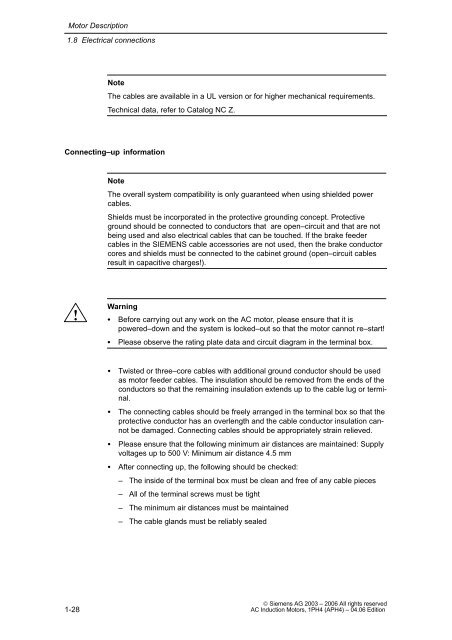
Motor Description<br />
1.8 Electrical connections<br />
1-28<br />
Note<br />
The cables are available in a UL version or for higher mechanical requirements.<br />
Technical data, refer to Catalog NC Z.<br />
Connecting–up information<br />
!<br />
Note<br />
The overall system compatibility is only guaranteed when using shielded power<br />
cables.<br />
Shields must be incorporated in the protective grounding concept. Protective<br />
ground should be connected to conductors that are open–circuit and that are not<br />
being used and also electrical cables that can be touched. If the brake feeder<br />
cables in the SIEMENS cable accessories are not used, then the brake conductor<br />
cores and shields must be connected to the cabinet ground (open–circuit cables<br />
result in capacitive charges!).<br />
Warning<br />
� Before carrying out any work on the <strong>AC</strong> motor, please ensure that it is<br />
powered–down and the system is locked–out so that the motor cannot re–start!<br />
� Please observe the rating plate data and circuit diagram in the terminal box.<br />
� Twisted or three–core cables with additional ground conductor should be used<br />
as motor feeder cables. The insulation should be removed from the ends of the<br />
conductors so that the remaining insulation extends up to the cable lug or terminal.<br />
� The connecting cables should be freely arranged in the terminal box so that the<br />
protective conductor has an overlength and the cable conductor insulation cannot<br />
be damaged. Connecting cables should be appropriately strain relieved.<br />
� Please ensure that the following minimum air distances are maintained: Supply<br />
voltages up to 500 V: Minimum air distance 4.5 mm<br />
� After connecting up, the following should be checked:<br />
– The inside of the terminal box must be clean and free of any cable pieces<br />
– All of the terminal screws must be tight<br />
– The minimum air distances must be maintained<br />
– The cable glands must be reliably sealed<br />
© <strong>Siemens</strong> AG 2003 – 2006 All rights reserved<br />
<strong>AC</strong> <strong>Induction</strong> <strong>Motors</strong>, <strong>1PH4</strong> (APH4) – 04.06 Edition