Configuration Manual AC Induction Motors 1PH4 - Siemens ...
Configuration Manual AC Induction Motors 1PH4 - Siemens ...
Configuration Manual AC Induction Motors 1PH4 - Siemens ...

You also want an ePaper? Increase the reach of your titles
YUMPU automatically turns print PDFs into web optimized ePapers that Google loves.
Motor Components<br />
3.3 Holding brake<br />
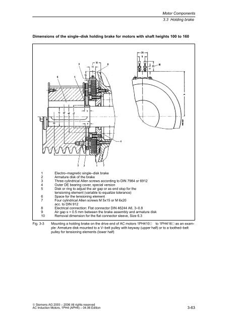
Dimensions of the single–disk holding brake for motors with shaft heights 100 to 160<br />
1 Electro–magnetic single–disk brake<br />
2 Armature disk of the brake<br />
3 Three cylindrical Allen screws according to DIN 7984 or 6912<br />
4 Outer DE bearing cover, special version<br />
5 Disk or ring to adjust the air gap or as end stop for the<br />
tensioning element (variable to equalize tolerance)<br />
6 Space for the tensioning element<br />
7 Four cylindrical Allen screws M 5x15 or M 6x20<br />
acc. to DIN 912<br />
8 Electrical connection: Flat connector DIN 46244 A6, 3–0.8<br />
9 Air gap s = 0.5 mm between the brake assembly and armature disk<br />
10 Removal dimension for the flat connector sleeve, Size 6.3<br />
Fig. 3-3 Mounting a holding brake on the drive end of <strong>AC</strong> motors <strong>1PH4</strong>10� to <strong>1PH4</strong>16� as an example:<br />
Armature disk mounted to a V–belt pulley with keyway (upper half) or to a toothed–belt<br />
pulley for tensioning elements (lower half)<br />
© <strong>Siemens</strong> AG 2003 – 2006 All rights reserved<br />
<strong>AC</strong> <strong>Induction</strong> <strong>Motors</strong>, <strong>1PH4</strong> (APH4) – 04.06 Edition<br />
3-63