EPP Europe P2.2023

You also want an ePaper? Increase the reach of your titles
YUMPU automatically turns print PDFs into web optimized ePapers that Google loves.
» PCB & ASSEMBLY<br />
White paper: ‘flying’ SMD components - part two<br />
How to combat the ‘flying’ SMD<br />
components phenomenon<br />
The first part of this white paper - published in our April 2023 issue - described how<br />
the investigation to determine the influence of flow temperature on SOD323s being<br />
blown away was conducted. This second part examines the test results, and reveals<br />
the best methods to ensure these components are reliably processed.<br />
» Dr. Paul Wild, Carsten Giersberg, Rehm Thermal Systems GmbH<br />
The simulation results demonstrate that the<br />
maximum forces act upon different components<br />
and that there is no component for which a force resulting<br />
from all three directions of action must be<br />
taken into account as the greatest force.<br />
As the graphs opposite show, the maximum force<br />
in the X direction acts upon the smaller side surface<br />
of component 8. This force amounts to 45 µN. The<br />
maximum force in the Y direction (buoyancy force)<br />
acts upon the upper side of component 14 and<br />
amounts to 25 µN. The maximum force in the Z direction<br />
(graph on page 40) acts upon the larger side<br />
surface of component 25 and amounts to 52 µN. As<br />
the forces in the X and Z directions act upon component<br />
side surfaces of equal size, only the force in the<br />
Z direction will be regarded as the blowing force in<br />
the following, and the force in the Y direction will be<br />
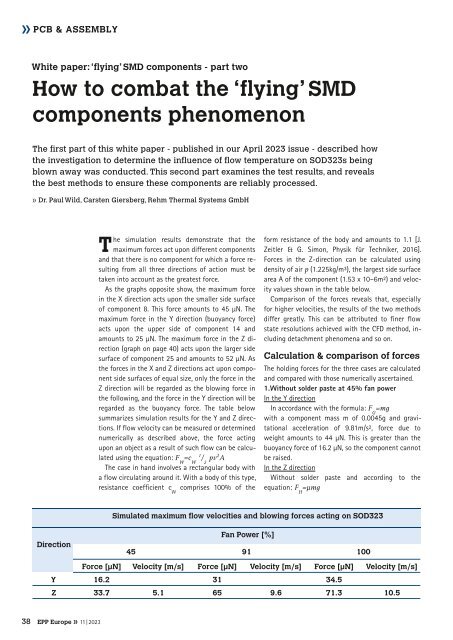
regarded as the buoyancy force. The table below<br />
summarizes simulation results for the Y and Z directions.<br />
If flow velocity can be measured or determined<br />
numerically as described above, the force acting<br />
upon an object as a result of such flow can be calculated<br />
using the equation: F W<br />
=c 1 W<br />
/ 2<br />
pv 2 A<br />
The case in hand involves a rectangular body with<br />
a flow circulating around it. With a body of this type,<br />
resistance coefficient c W<br />
comprises 100% of the<br />
form resistance of the body and amounts to 1.1 [J.<br />
Zeitler & G. Simon, Physik für Techniker, 2016].<br />
Forces in the Z-direction can be calculated using<br />
density of air p (1.225kg/m³), the largest side surface<br />
area A of the component (1.53 x 10⁻⁶m²) and velocity<br />
values shown in the table below.<br />
Comparison of the forces reveals that, especially<br />
for higher velocities, the results of the two methods<br />
differ greatly. This can be attributed to finer flow<br />
state resolutions achieved with the CFD method, including<br />
detachment phenomena and so on.<br />
Calculation & comparison of forces<br />
The holding forces for the three cases are calculated<br />
and compared with those numerically ascertained.<br />
1. Without solder paste at 45% fan power<br />
In the Y direction<br />
In accordance with the formula: F G<br />
=mg<br />
with a component mass m of 0.0045g and gravitational<br />
acceleration of 9.81m/s², force due to<br />
weight amounts to 44 µN. This is greater than the<br />
buoyancy force of 16.2 µN, so the component cannot<br />
be raised.<br />
In the Z direction<br />
Without solder paste and according to the<br />
equation: F H<br />
=μmg<br />
Simulated maximum flow velocities and blowing forces acting on SOD323<br />
Direction<br />
45<br />
Fan Power [%]<br />
91<br />
100<br />
Force [µN]<br />
Velocity [m/s]<br />
Force [µN]<br />
Velocity [m/s]<br />
Force [µN]<br />
Velocity [m/s]<br />
Y<br />
16.2<br />
31<br />
34.5<br />
Z<br />
33.7<br />
5.1<br />
65<br />
9.6<br />
71.3<br />
10.5<br />
38 <strong>EPP</strong> <strong>Europe</strong> » 11 | 2023