SERVICE MANUAL - SONYRUS
SERVICE MANUAL - SONYRUS
SERVICE MANUAL - SONYRUS

Create successful ePaper yourself
Turn your PDF publications into a flip-book with our unique Google optimized e-Paper software.
DSC-W1/W12<br />
1-4-3. Adjusting Method<br />
1. CAMERA Adjustment 1<br />
[Automatic Adjustment Program execution items and<br />
sequence]<br />
1. Data Setting during Camera Adj.<br />
2. Flange Back Adj.<br />
3. Release of Data Setting during Camera Adj.<br />
[Adjusting method]<br />
1) Click the [CAMERA Adjustment 1 Start] button.<br />
2) The Automatic Adjustment Program executes “1. Data Setting<br />
during Camera Adj.”.<br />
3) Upon successful completion of the “1. Data Setting during<br />
Camera Adj.”, the following message is displayed. Set the subject<br />
by referring to “Preparation of Flange Back Adj.”.<br />
Fig. 6-1-16<br />
4) If the [OK] button is clicked, “2. Flange Back Adj.” and “3.<br />
Release of Data Setting during Camera Adj.” will be executed.<br />
5) Upon successful completion of all items of the CAMERA<br />
Adjustment 1, the following message is displayed. Click the<br />
[OK] button.<br />
Fig. 6-1-17<br />
6-14<br />
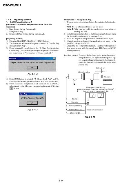
Preparation of Flange Back Adj.<br />
1) The minipattern box is installed as shown in the following figure.<br />
Note 1: The attachment lenses are not used.<br />
Note 2: Take care not to hit the mini-pattern box when extending<br />
the lens.<br />
2) Install the minipattern box so that the distance between it and<br />
the front of lens of camera is less than 3 cm.<br />
3) Make the height of minipattern box and the camera equal.<br />
4) Check the output voltage of the regulated power supply is the<br />
specified voltage ± 0.01 Vdc.<br />
5) Check that the center of Siemens star chart meets the center of<br />
shot image screen with the zoom lens at TELE end and WIDE<br />
end respectively.<br />
Specified voltage: The specified voltage varies according to the<br />
minipattern box, so adjustment the power supply<br />
output voltage to the specified voltage written<br />
on the sheet which is supplied with the minipattern<br />
box.<br />
Red (+)<br />
Black (–)<br />
Yellow (SENS +)<br />
White (SENS –)<br />
Black (GND)<br />
Minipattern box<br />
Fig. 6-1-18<br />
Below 3 cm<br />
Need not connected<br />
Camera<br />
Regulated power supply<br />
Output voltage : Specified voltage ± 0.01 Vdc<br />
Output current : more than 3.5 A