38059-Satchwell Inter. Guide 05
38059-Satchwell Inter. Guide 05
38059-Satchwell Inter. Guide 05

Create successful ePaper yourself
Turn your PDF publications into a flip-book with our unique Google optimized e-Paper software.
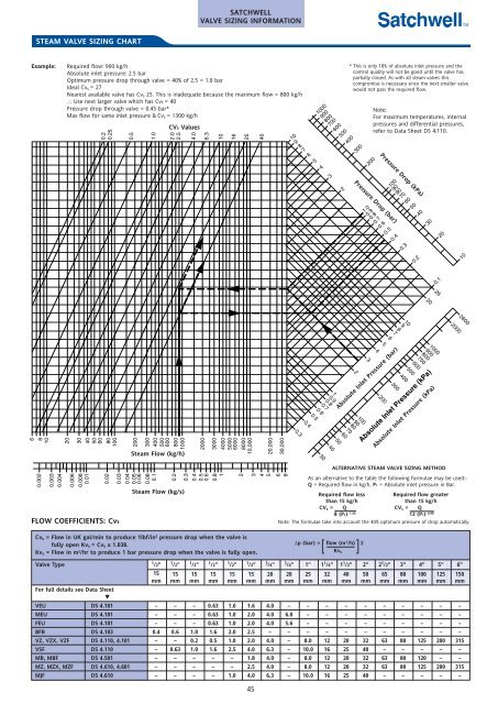
STEAM VALVE SIZING CHART<br />
Example: Required flow: 900 kg/h<br />
Absolute inlet pressure: 2.5 bar<br />
Optimum pressure drop through valve = 40% of 2.5 = 1.0 bar<br />
Ideal Cvs = 27<br />
Nearest available valve has Cvs 25. This is inadequate because the maximum flow = 800 kg/h<br />
∴ Use next larger valve which has Cvs = 40<br />
Pressure drop through valve = 0.45 bar*<br />
Max flow for same inlet pressure & Cvs = 1300 kg/h<br />
6<br />
8<br />
10<br />
0.002<br />
0.003<br />
0.004<br />
20<br />
30<br />
40<br />
50<br />
60<br />
80<br />
100<br />
0.006<br />
0.008<br />
0.01<br />
0.2<br />
0.25<br />
0.02<br />
FLOW COEFFICIENTS: Cvs<br />
0.5<br />
200<br />
300<br />
400<br />
500<br />
600<br />
800<br />
1000<br />
Cvs = Flow in UK gal/min to produce 1lbf/in 2 pressure drop when the valve is<br />
fully open Kvs = Cvs x 1.038.<br />
Kvs = Flow in m 2 /hr to produce 1 bar pressure drop when the valve is fully open.<br />
1.0<br />
0.03<br />
0.04<br />
0.<strong>05</strong><br />
0.06<br />
0.08<br />
0.1<br />
CVs Values<br />
2.0<br />
2.5<br />
Steam Flow (kg/h)<br />
0.2<br />
Steam Flow (kg/s)<br />
4.0<br />
SATCHWELL<br />
VALVE SIZING INFORMATION<br />
2000<br />
6.3<br />
10<br />
0.3<br />
0.4<br />
0.5<br />
0.6<br />
0.8<br />
1<br />
16<br />
3000<br />
4000<br />
5000<br />
6000<br />
8000<br />
10,000<br />
2<br />
25<br />
∆p (bar) = flow (m 3 /h) 2<br />
Valve Type 1 /2” 1 /2” 1 /2” 1 /2” 1 /2” 1 /2” 3 /4” 3 /4” 1” 11 /4” 11 /2” 2” 21 /2” 3” 4” 5” 6”<br />
15 15 15 15 15 15 20 20 25 32 40 50 65 80 100 125 150<br />
For full details see Data Sheet<br />
▼<br />
mm mm mm mm mm mm mm mm mm mm mm mm mm mm mm mm mm<br />
VEU DS 4.101 – – – 0.63 1.0 1.6 4.0 – – – – – – – – – –<br />
MEU DS 4.101 – – – 0.63 1.0 2.0 4.0 6.0 – – – – – – – – –<br />
FEU DS 4.101 – – – 0.63 1.0 2.0 4.0 5.6 – – – – – – – – –<br />
BFB DS 4.103 0.4 0.6 1.0 1.6 2.0 2.5 – – – – – – – – – – –<br />
VZ, VZX, VZF DS 4.110, 4.101 – – 0.2 0.5 1.0 2.0 4.0 – 8.0 12 20 32 63 80 125 200 315<br />
VSF DS 4.110 – 0.63 1.0 1.6 2.5 4.0 6.3 – 10.0 16 25 40 – – – – –<br />
MB, MBF DS 4.501 – – – – – 1.8 4.0 – 8.0 12 20 32 63 80 120 – –<br />
MZ, MZX, MZF DS 4.610, 4.601 – – – – – 2.5 4.0 – 8.0 12 20 32 63 80 125 200 315<br />
MJF DS 4.610 – – – – 1.0 4.0 6.3 – 10.0 16 25 40 – – – – –<br />
45<br />
40<br />
20,000<br />
3<br />
4<br />
5<br />
30,000<br />
6<br />
8<br />
10<br />
9<br />
8<br />
7<br />
6<br />
5<br />
4<br />
0.3<br />
1<br />
0.9<br />
0.8<br />
0.7<br />
0.6<br />
0.5<br />
0.4<br />
1000<br />
900<br />
800<br />
700<br />
600<br />
500<br />
30<br />
3<br />
100<br />
90<br />
80<br />
70<br />
60<br />
50<br />
40<br />
2<br />
Kvs<br />
* This is only 18% of absolute inlet pressure and the<br />
control quality will not be good until the valve has<br />
partially closed. As with all steam valves this<br />
compromise is necessary since the next smaller valve<br />
would not pass the required flow.<br />
400<br />
2<br />
300<br />
3<br />
200<br />
Pressure Drop (bar)<br />
1.0<br />
0.9<br />
0.8<br />
0.7<br />
0.6<br />
0.5<br />
0.4<br />
Pressure Drop (kPa)<br />
10<br />
9<br />
8<br />
7<br />
6<br />
5<br />
4<br />
200<br />
100<br />
90<br />
80<br />
70<br />
60<br />
50<br />
40<br />
300<br />
0.3<br />
1000<br />
900<br />
800<br />
700<br />
600<br />
500<br />
400<br />
Absolute Inlet Pressure (bar)<br />
Note:<br />
For maximum temperatures, internal<br />
pressures and differential pressures,<br />
refer to Data Sheet DS 4.110.<br />
0.2<br />
30<br />
20<br />
Absolute Inlet Pressure (kPa)<br />
ALTERNATIVE STEAM VALVE SIZING METHOD<br />
0.1<br />
26<br />
20<br />
2000<br />
10<br />
2600<br />
As an alternative to the table the following formulae may be used:-<br />
Q = Required flow in kg/h, P1 = Absolute inlet pressure in Bar.<br />
Required flow less<br />
than 15 kg/h<br />
CVs = Q<br />
8 (P1) 1.56<br />
Pressure Drop (bar)<br />
Absolute Inlet Pressure (bar)<br />
Pressure Drop (kPa)<br />
Absolute Inlet Pressure (kPa)<br />
Required flow greater<br />
than 15 kg/h<br />
CVs = Q<br />
13 (P1) 0.98<br />
Note: The formulae take into account the 40% optimum pressure of drop automatically.