channel - Advances in Electronics and Telecommunications
channel - Advances in Electronics and Telecommunications
channel - Advances in Electronics and Telecommunications

You also want an ePaper? Increase the reach of your titles
YUMPU automatically turns print PDFs into web optimized ePapers that Google loves.
STAMATIOU et al.: SPATIAL MULTIPLEXING IN RANDOM WIRELESS NETWORKS 11<br />
Transm. cap. (nats/symbol/m 2 )<br />
0.0003<br />
0.00025<br />
0.0002<br />
0.00015<br />
N = 8<br />
0.0001<br />
5e-05<br />
N = 4<br />
DB, eq. (43)<br />
Sim, DB<br />
ZF, eq. (32)<br />
Sim, ZF<br />
VB, eq. (36)<br />
Sim, VB<br />
0<br />
1 2 3 4 5 6 7 8<br />
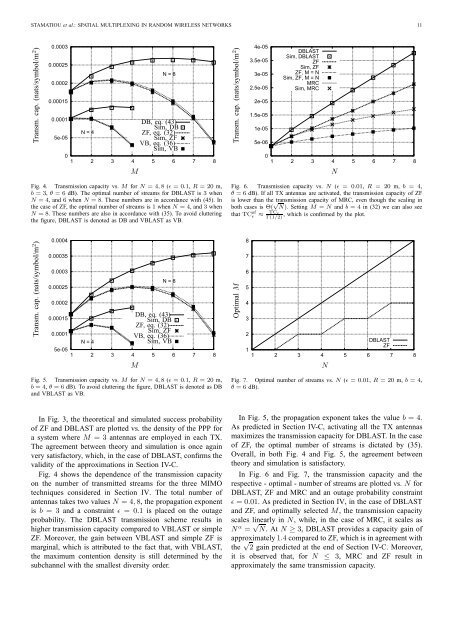
Fig. 4. Transmission capacity vs. M for N = 4, 8 (ǫ = 0.1, R = 20 m,<br />
b = 3, θ = 6 dB). The optimal number of streams for DBLAST is 3 when<br />
N = 4, <strong>and</strong> 6 when N = 8. These numbers are <strong>in</strong> accordance with (45). In<br />
the case of ZF, the optimal number of streams is 1 when N = 4, <strong>and</strong> 3 when<br />
N = 8. These numbers are also <strong>in</strong> accordance with (35). To avoid clutter<strong>in</strong>g<br />
the figure, DBLAST is denoted as DB <strong>and</strong> VBLAST as VB.<br />
Transm. cap. (nats/symbol/m 2 )<br />
0.0004<br />
0.00035<br />
0.0003<br />
0.00025<br />
0.0002<br />
M<br />
N = 8<br />
0.00015<br />
0.0001<br />
5e-05<br />
N = 4<br />
DB, eq. (43)<br />
Sim, DB<br />
ZF, eq. (32)<br />
Sim, ZF<br />
VB, eq. (36)<br />
Sim, VB<br />
1 2 3 4 5 6 7 8<br />
Fig. 5. Transmission capacity vs. M for N = 4, 8 (ǫ = 0.1, R = 20 m,<br />
b = 4, θ = 6 dB). To avoid clutter<strong>in</strong>g the figure, DBLAST is denoted as DB<br />
<strong>and</strong> VBLAST as VB.<br />
In Fig. 3, the theoretical <strong>and</strong> simulated success probability<br />
of ZF <strong>and</strong> DBLAST are plotted vs. the density of the PPP for<br />
a system where M = 3 antennas are employed <strong>in</strong> each TX.<br />
The agreement between theory <strong>and</strong> simulation is once aga<strong>in</strong><br />
very satisfactory, which, <strong>in</strong> the case of DBLAST, confirms the<br />
validity of the approximations <strong>in</strong> Section IV-C.<br />
Fig. 4 shows the dependence of the transmission capacity<br />
on the number of transmitted streams for the three MIMO<br />
techniques considered <strong>in</strong> Section IV. The total number of<br />
antennas takes two values N = 4, 8, the propagation exponent<br />
is b = 3 <strong>and</strong> a constra<strong>in</strong>t ǫ = 0.1 is placed on the outage<br />
probability. The DBLAST transmission scheme results <strong>in</strong><br />
higher transmission capacity compared to VBLAST or simple<br />
ZF. Moreover, the ga<strong>in</strong> between VBLAST <strong>and</strong> simple ZF is<br />
marg<strong>in</strong>al, which is attributed to the fact that, with VBLAST,<br />
the maximum contention density is still determ<strong>in</strong>ed by the<br />
sub<strong>channel</strong> with the smallest diversity order.<br />
M<br />
Transm. cap. (nats/symbol/m 2 )<br />
4e-05<br />
3.5e-05<br />
3e-05<br />
2.5e-05<br />
2e-05<br />
1.5e-05<br />
1e-05<br />
5e-06<br />
DBLAST<br />
Sim, DBLAST<br />
ZF<br />
Sim, ZF<br />
ZF, M = N<br />
Sim, ZF, M = N<br />
MRC<br />
Sim, MRC<br />
0<br />
1 2 3 4 5 6 7 8<br />
Fig. 6. Transmission capacity vs. N (ǫ = 0.01, R = 20 m, b = 4,<br />
θ = 6 dB). If all TX antennas are activated, the transmission capacity of ZF<br />
is lower than the transmission capacity of MRC, even though the scal<strong>in</strong>g <strong>in</strong><br />
both cases is Θ( √ N). Sett<strong>in</strong>g M = N <strong>and</strong> b = 4 <strong>in</strong> (32) we can also see<br />
that TCzf TCǫ<br />
ǫ ≈ , which is confirmed by the plot.<br />
Γ(1/2)<br />
Optimal M<br />
8<br />
7<br />
6<br />
5<br />
4<br />
3<br />
2<br />
1<br />
DBLAST<br />
ZF<br />
1 2 3 4 5 6 7 8<br />
N<br />
Fig. 7. Optimal number of streams vs. N (ǫ = 0.01, R = 20 m, b = 4,<br />
θ = 6 dB).<br />
In Fig. 5, the propagation exponent takes the value b = 4.<br />
As predicted <strong>in</strong> Section IV-C, activat<strong>in</strong>g all the TX antennas<br />
maximizes the transmission capacity for DBLAST. In the case<br />
of ZF, the optimal number of streams is dictated by (35).<br />
Overall, <strong>in</strong> both Fig. 4 <strong>and</strong> Fig. 5, the agreement between<br />
theory <strong>and</strong> simulation is satisfactory.<br />
In Fig. 6 <strong>and</strong> Fig. 7, the transmission capacity <strong>and</strong> the<br />
respective - optimal - number of streams are plotted vs. N for<br />
DBLAST, ZF <strong>and</strong> MRC <strong>and</strong> an outage probability constra<strong>in</strong>t<br />
ǫ = 0.01. As predicted <strong>in</strong> Section IV, <strong>in</strong> the case of DBLAST<br />
<strong>and</strong> ZF, <strong>and</strong> optimally selected M, the transmission capacity<br />
scales l<strong>in</strong>early <strong>in</strong> N, while, <strong>in</strong> the case of MRC, it scales as<br />
N α = √ N. At N ≥ 3, DBLAST provides a capacity ga<strong>in</strong> of<br />
approximately 1.4 compared to ZF, which is <strong>in</strong> agreement with<br />
the √ 2 ga<strong>in</strong> predicted at the end of Section IV-C. Moreover,<br />
it is observed that, for N ≤ 3, MRC <strong>and</strong> ZF result <strong>in</strong><br />
approximately the same transmission capacity.<br />
N