channel - Advances in Electronics and Telecommunications
channel - Advances in Electronics and Telecommunications
channel - Advances in Electronics and Telecommunications

Create successful ePaper yourself
Turn your PDF publications into a flip-book with our unique Google optimized e-Paper software.
80 ADVANCES IN ELECTRONICS AND TELECOMMUNICATIONS, VOL. 1, NO. 1, APRIL 2010<br />
Please note that, <strong>in</strong> the future, any other tools provid<strong>in</strong>g such<br />
extended features, concern<strong>in</strong>g the presented goals compared<br />
to SynDEx, would be worth to be considered. Moreover, this<br />
methodology could be also exp<strong>and</strong>ed at the top of the design<br />
flow, towards higher level design tools based on UML. The<br />
<strong>in</strong>put graphs from SynDEx could easily be generated from<br />
previous graphs def<strong>in</strong>ed <strong>in</strong> a UML environment. A bridge<br />
between A3S graphs <strong>and</strong> SynDEx graphs for <strong>in</strong>stance would<br />
be straightforward. SynDEx would then only take the tim<strong>in</strong>g<br />
non-functional parameter from A3S. The other non functional<br />
parameters (power consumption, memory <strong>and</strong> surface considerations)<br />
taken <strong>in</strong>to account <strong>in</strong> A3S would not be used <strong>in</strong> the<br />
mapp<strong>in</strong>g process itself but would at least have been considered<br />
at the very beg<strong>in</strong>n<strong>in</strong>g of the design, which is better than<br />
noth<strong>in</strong>g. Of course, the long term goal is to really <strong>in</strong>tegrate all<br />
non-functional parameters <strong>in</strong> the complete design flow.<br />
VI. DESIGN EXAMPLES (IMPLEMENTATION)<br />
Whatever the methodology is, the necessary SDR development<br />
efforts are, on one h<strong>and</strong>, the cod<strong>in</strong>g of an application <strong>in</strong><br />
order to simulate <strong>and</strong> validate the correct radio functionality,<br />
<strong>and</strong> on the other h<strong>and</strong>, the cod<strong>in</strong>g of a low level software<br />
associated with the hardware components <strong>in</strong> order to prototype<br />
the radio on the platform. The lack of methodology results <strong>in</strong><br />
the repetition of this process from scratch for each new design.<br />
This is the current SDR doma<strong>in</strong> situation.<br />
The methodology suggested <strong>in</strong> this paper permits to share<br />
development efforts for both:<br />
- radio signal process<strong>in</strong>g IPs,<br />
- low level software of hardware architecture.<br />
This is the ma<strong>in</strong> cause of the acceleration of the methodology;<br />
together with a set of concepts particularly adequate<br />
for SDR design <strong>and</strong> expla<strong>in</strong>ed earlier. We suggest <strong>in</strong> the<br />
follow<strong>in</strong>g paragraphs to illustrate the methodology efficiency<br />
<strong>in</strong> various design scenarii. Please note that it will be illustrated<br />
that SDR design is tackled <strong>in</strong> its widest acceptation here.<br />
This <strong>in</strong>volves also cross-layer design, as PHY (radio) layer,<br />
as well as application (video) layer may be merged with<br />
the proposed design approach. This proves also the relevance<br />
of the approach for general heterogeneous embedded design<br />
outside SDR.<br />
A. Start<strong>in</strong>g from scratch<br />
Our first attempt to develop an SDR is as simple as a<br />
broadcast FM receiver development. This is a play activity<br />
for a hundred percent software radio implementation, s<strong>in</strong>ce<br />
the antenna is directly connected to the analogue to digital<br />
converter. The selected platform is a Pentek P4292 made<br />
of four TMS320C6203 DSPs. All this process<strong>in</strong>g power is<br />
much greater than necessary, <strong>and</strong> is only used to evaluate<br />
the methodology <strong>in</strong> a multi-process<strong>in</strong>g context. First of all,<br />
the work consists <strong>in</strong> develop<strong>in</strong>g the FM receiver data-flow<br />
graph with a component based approach, <strong>and</strong> the fixed-po<strong>in</strong>t<br />
C language code for the content of each IP. This represents<br />
a time period rang<strong>in</strong>g from a few days to a couple of weeks<br />
of work at the most, depend<strong>in</strong>g on the previous knowledge of<br />
the modulation, the receiver quality (stereo or mono, choice<br />
High level description of FM demodulation<br />
<strong>in</strong>put<br />
Coef_filter<br />
trans_FIR1<br />
Acquisition<br />
<strong>in</strong><br />
base b<strong>and</strong><br />
ADC_acquisition<br />
FIR1<br />
FIR2<br />
SIN_TBL<br />
s<strong>in</strong>_tbl<br />
Hierarchical graph<br />
<strong>in</strong>side FM demodulation<br />
o<br />
Coef_filter1<br />
Coef_filter2<br />
Constants<br />
Downsampl<strong>in</strong>g<br />
filter<strong>in</strong>g<br />
to 441kbps<br />
FIR1<br />
<strong>in</strong>put output<br />
Coef_filter<br />
trans_o1<br />
trans_i1<br />
diff_state<br />
Frequency acquisition<br />
ACQ_frequency<br />
xsc_P C<br />
Cordic<br />
Cordic<br />
trans_FIR1<br />
VP<br />
o<br />
FM Demodulation<br />
FM_data<br />
constra<strong>in</strong>_DSP1<br />
<strong>in</strong>put<br />
chA<br />
trans_FIR1 trans_FIR1<br />
Coef_filter1 diff_state<br />
diff_state state_chA<br />
state_chA LplusR<br />
LplusR Lm<strong>in</strong>usR<br />
Coef_filter2 chB<br />
Lm<strong>in</strong>usR state_chB<br />
state_chB<br />
Vp<br />
s<strong>in</strong>_tbl<br />
Vp<br />
Phi<br />
Phi<br />
diff_state<br />
constra<strong>in</strong>_DSP1<br />
LplusR<br />
Coef_filter2<br />
<strong>in</strong>put output<br />
diff_state diff_state<br />
i o<br />
LplusR<br />
i o<br />
trans_FIR1<br />
constra<strong>in</strong>_DSP1<br />
i o<br />
MEM_chA<br />
constra<strong>in</strong>_DSP1<br />
i o<br />
Lm<strong>in</strong>usR<br />
Phi<br />
Vp<br />
s<strong>in</strong>_tbl<br />
PHI<br />
diff_state<br />
Downsampl<strong>in</strong>g<br />
filetr<strong>in</strong>g<br />
to 44.1kbps L+R<br />
GetLplusR<br />
Coef_filter2 output<br />
<strong>in</strong>put trans_o<br />
trans_i<br />
Downsampl<strong>in</strong>g<br />
filetr<strong>in</strong>g<br />
to 44.1kbps L-R<br />
GetLm<strong>in</strong>usR<br />
Coef_filter2 trans_o<br />
trans_i output<br />
<strong>in</strong>put Vp_o<br />
s<strong>in</strong>_tbl phi_o<br />
Vp_i<br />
phi_i<br />
<strong>in</strong>terleav<strong>in</strong>g<br />
xsc_PC<br />
<strong>in</strong>1<br />
<strong>in</strong>2<br />
Lm<strong>in</strong>usR<br />
i o<br />
MEM_chB<br />
i o<br />
i o i o<br />
Delay between iteration<br />
Interleav<strong>in</strong>g<br />
left <strong>and</strong> right<br />
<strong>channel</strong>s<br />
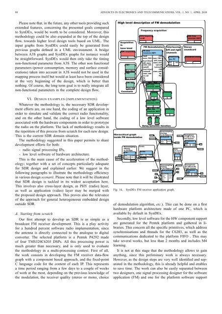
Fig. 14. SynDEx FM receiver application graph.<br />
LplusR<br />
state_chA<br />
Demux<br />
Left <strong>channel</strong><br />
Right <strong>channel</strong><br />
fm_demix<br />
A<br />
B<br />
out<br />
Lm<strong>in</strong>usR<br />
Phi<br />
Vp<br />
L<br />
R<br />
state_chB<br />
Deemphasis<br />
of 3dB on the<br />
left <strong>channel</strong><br />
demphasis<br />
chA<br />
<strong>in</strong>put<br />
state_i<br />
ADC_Freq<br />
constra<strong>in</strong>_DSP1<br />
o<br />
Stereo<br />
soundcard<br />
Soundcard_stereo<br />
i1<br />
output<br />
state_o<br />
Deemphasis<br />
of 3dB on the<br />
right <strong>channel</strong><br />
demphasis<br />
chB<br />
<strong>in</strong>put output<br />
state_i state_o<br />
chA<br />
state_chA<br />
chB<br />
state_chB<br />
of demodulation algorithm, etc.). This can be done on a first<br />
hardware platform architecture made of one PC, which is<br />
available by default <strong>in</strong> SynDEx.<br />
Secondly, low level software for the HW component support<br />
are generated for the Pentek platform <strong>and</strong> gathered <strong>in</strong> libraries.<br />
This concern all the specific primitives, which address<br />
synchronisations <strong>and</strong> threads for the C6203, as well as the<br />
communications dedicated to the platform FIFO . This may<br />
take several weeks, but less than 2 months <strong>and</strong> <strong>in</strong>cludes M4<br />
learn<strong>in</strong>g.<br />
It is not at this stage that the methodology allows to ga<strong>in</strong><br />
anyth<strong>in</strong>g, s<strong>in</strong>ce this prelim<strong>in</strong>ary work is always necessary.<br />
However, as the design steps are very well identified <strong>and</strong> separated<br />
<strong>in</strong> the methodology, this is already helpful <strong>and</strong> enables<br />
to save time. The work can also be easily separated between<br />
two designers, one signal process<strong>in</strong>g designer for the software<br />
application (FM) <strong>and</strong> one for the platform software support