channel - Advances in Electronics and Telecommunications
channel - Advances in Electronics and Telecommunications
channel - Advances in Electronics and Telecommunications

You also want an ePaper? Increase the reach of your titles
YUMPU automatically turns print PDFs into web optimized ePapers that Google loves.
52 ADVANCES IN ELECTRONICS AND TELECOMMUNICATIONS, VOL. 1, NO. 1, APRIL 2010<br />
properties<br />
�<br />
0 t ≤ 0<br />
q(t) =<br />
1<br />
2 t ≥ LT .<br />
The phase pulse is usually def<strong>in</strong>ed as the <strong>in</strong>tegral of a<br />
frequency pulse s(t)<br />
q(t) =<br />
� t<br />
−∞<br />
s(τ)dτ .<br />
Different frequency pulse shapes have been proposed [5]. The<br />
most commonly used are the rectangular (REC) <strong>and</strong> the raisedcos<strong>in</strong>e<br />
(RC) frequency pulses. A CPM scheme is then def<strong>in</strong>ed<br />
by specify<strong>in</strong>g its parameters M, h, L <strong>and</strong> s(t).<br />
When a signal like (2) enters a nonl<strong>in</strong>ear device, whose<br />
characteristic is modeled as <strong>in</strong> (1), it undergoes amplitude <strong>and</strong><br />
phase distortion. However, s<strong>in</strong>ce its amplitude<br />
�<br />
2Es<br />
|r| =<br />
T<br />
is constant, the amplitude distortion results <strong>in</strong> a ga<strong>in</strong> factor<br />
A[ � 2Es/T ] <strong>and</strong> the phase distortion results <strong>in</strong> a constant<br />
phase shift Φ[ � 2Es/T ], which is compensated for by the<br />
carrier phase recovery circuit at the receiver.<br />
A nice feature of CPM signals is their b<strong>and</strong>width efficiency:<br />
although the PSD of CPM signals has <strong>in</strong>f<strong>in</strong>ite support, it<br />
exhibits a large ma<strong>in</strong> lobe centered around the carrier frequency<br />
with rapidly decreas<strong>in</strong>g tails. The width <strong>and</strong> height<br />
of the ma<strong>in</strong> lobe are related to parameter L, also called the<br />
correlation length. In fact, a large L <strong>in</strong>duces a correlation<br />
between adjacent symbols <strong>in</strong> the modulated process. S<strong>in</strong>ce <strong>in</strong><br />
this case the autocorrelation has a larger support, the signal<br />
power is more concentrated around the carrier frequency,<br />
result<strong>in</strong>g <strong>in</strong> a narrower b<strong>and</strong>width. The b<strong>and</strong>width efficiency<br />
results <strong>in</strong>creased but, as we will see later, high values for L<br />
result <strong>in</strong> a higher receiver complexity.<br />
The properties of CPM have been the subject of several<br />
studies <strong>in</strong> the past. Some key advances have been performed<br />
after <strong>in</strong>troduc<strong>in</strong>g new CPM signal representations, like the<br />
Laurent’s decomposition (LD) [13], which is one of the most<br />
cited <strong>and</strong> exploited <strong>in</strong> the scientific literature. The LD writes<br />
a b<strong>in</strong>ary CPM as the sum of amplitude-modulated pulses each<br />
hav<strong>in</strong>g dist<strong>in</strong>ct durations <strong>and</strong> shapes. As a result, a cont<strong>in</strong>uousphase<br />
modulator can be implemented as a bank of pulseamplitude<br />
modulators, each us<strong>in</strong>g a different pulse, whose<br />
outputs are added to form the cont<strong>in</strong>uous-phase modulated<br />
signal. The success of the LD dur<strong>in</strong>g the early days of CPM<br />
is perhaps due to a characteristic that was frequently exploited<br />
for the design of reduced-complexity modulators <strong>and</strong> receivers.<br />
In fact, although the number of pulses result<strong>in</strong>g from the<br />
LD may be very large, an accurate approximation can be<br />
obta<strong>in</strong>ed us<strong>in</strong>g only a small subset of them, i.e., those with<br />
the largest energy. This result has been exploited <strong>in</strong> [14],<br />
where a low-complexity coherent receiver consist<strong>in</strong>g of a<br />
bank of matched filters followed by a Viterbi processor has<br />
been proposed. In [15], it has been exploited to design lowcomplexity<br />
receivers for SCCPM systems. The LD has been<br />
extended to non b<strong>in</strong>ary CPM <strong>in</strong> [16]. In [17] it has been used<br />
to derive capacity bounds based on multiple-access <strong>channel</strong><br />
theory.<br />
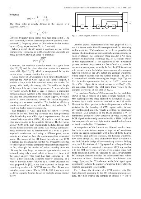
Fig. 2. Block diagram of the CPM encoder <strong>and</strong> modulator.<br />
Another popular representation has been proposed <strong>in</strong> [18]<br />
<strong>and</strong> it is known as the Rimoldi decomposition (RD). Accord<strong>in</strong>g<br />
to this result, the CPM modulator can be decomposed <strong>in</strong>to the<br />
cascade of a time-<strong>in</strong>variant convolutional encoder operat<strong>in</strong>g on<br />
r<strong>in</strong>gs of <strong>in</strong>tegers (the cont<strong>in</strong>uous-phase encoder, CPE) <strong>and</strong> a<br />
memoryless modulator (MM) (see Fig. 2). A relevant feature<br />
of this representation is the separation of the modulation<br />
process <strong>in</strong>to two subprocesses, the first of which accounts for<br />
memory across adjacent symbols. In fact, the CPE is a device<br />
with memory, while the MM performs a memoryless mapp<strong>in</strong>g<br />
between symbols at the CPE output <strong>and</strong> complex waveforms<br />
whose support extends over one symbol <strong>in</strong>terval. The CPE is<br />
a convolutional encoder operat<strong>in</strong>g on <strong>in</strong>teger r<strong>in</strong>gs ZM <strong>and</strong><br />
ZP . Its trellis representation has Nσ = P M L−1 states <strong>and</strong><br />
Nǫ = P M L edges. At its output, vectors cn ∈ (ZM ) L × ZP<br />
are generated. F<strong>in</strong>ally, the MM maps these vectors to the<br />
complex waveforms of the MM set ΣMM.<br />
The maximum-likelihood (ML) receiver for the modulator<br />
shown <strong>in</strong> Fig. 2 consists of a bank of filters matched to the<br />
MM signal space (the space spanned by the signals <strong>in</strong> ΣMM)<br />
followed by a trellis processor matched to the CPE trellis.<br />
The matched filters provide to the trellis processor a sufficient<br />
statistics for the decod<strong>in</strong>g of CPM signal, which is usually<br />
implemented us<strong>in</strong>g the Viterbi algorithm, for maximumlikelihood<br />
(ML) detection or the BCJR algorithm [19] for<br />
maximum a-posteriori (MAP) detection. In coded systems, the<br />
BCJR algorithm is usually executed with<strong>in</strong> a SISO [20] block<br />
that computes the extr<strong>in</strong>sic <strong>in</strong>formation needed to implement<br />
an iterative turbo-like [21] receiver.<br />
A comparison of the Laurent <strong>and</strong> Rimoldi results shows<br />
that both representations require a large set of waveforms,<br />
whose size grows exponentially with L but, while the Laurent<br />
waveforms have different energies, the Rimoldi waveforms<br />
have equal energy ES. This characteristic made it difficult to<br />
use the RD for the design of low-complexity receivers for long<br />
time, until the Authors of [22] proposed an orthogonalization<br />
technique based on pr<strong>in</strong>cipal components (PC) <strong>and</strong> applied<br />
it to the MM waveforms. In brief, given a signal space with<br />
f<strong>in</strong>ite dimension like the one spanned by the MM waveforms,<br />
PC orthogonalization provides the orthonormal basis whose<br />
truncation to fewer dimensions results <strong>in</strong> m<strong>in</strong>imum error<br />
energy. Apply<strong>in</strong>g the PC technique to the MM signal space<br />
significantly reduces the number of matched filters while the<br />
result<strong>in</strong>g degradation is negligible.<br />
Fig. 3 shows the structure of a CPM receiver with filter<br />
bank designed accord<strong>in</strong>g to the PC orthogonalization procedure.<br />
The filter outputs are sampled at <strong>in</strong>stants t = nT to