

Selection and Testing of Electronic Components for LM
Selection and Testing of Electronic Components for LM
Selection and Testing of Electronic Components for LM

You also want an ePaper? Increase the reach of your titles
YUMPU automatically turns print PDFs into web optimized ePapers that Google loves.
Insulation: Solid<br />
polyethylene<br />
Conductor diameter: 0.5 mm<br />
Cable length: 500 m<br />
Insulation: Foamed<br />
polyethylene<br />
Conductor diameter: 0.5 mm<br />
Cable length: 500 m<br />
Insulation: Solid<br />
polyethylene<br />
Conductor diameter: 0.7 mm<br />
Cable length: 500 m<br />
Fig. 13<br />
RMS values <strong>of</strong> capacitance unbalance distribution<br />
<strong>for</strong> cross str<strong>and</strong>ed cable<br />
Each cross represents the RMS value <strong>of</strong> the 45 capacitance<br />
unbalance values within a 10-pair group<br />
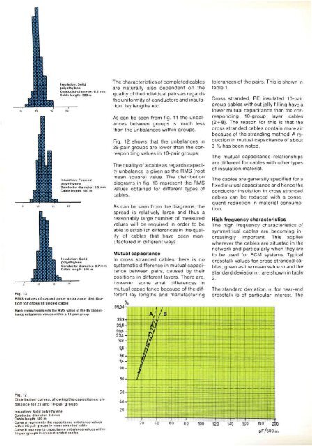
Fig. 12<br />
Distribution curves, showing the capacitance unbalance<br />
<strong>for</strong> 25 <strong>and</strong> 10-pair groups<br />
Insulation: Solid polyethylene<br />
Conductor diameter: 0.5 mm<br />
Cable length: 500 m<br />
Curve A represents the capacitance unbalance values<br />
within 25-pair groups In cross str<strong>and</strong>ed cable<br />
Curve B represents capacitance unbalance values within<br />
10-pair groups in cross str<strong>and</strong>ed cables<br />
The characteristics <strong>of</strong> completed cables<br />
are naturally also dependent on the<br />
quality <strong>of</strong> the individual pairs as regards<br />
the uni<strong>for</strong>mity <strong>of</strong> conductors <strong>and</strong> insulation,<br />
lay lengths etc.<br />
As can be seen from fig. 11 the unbalances<br />
between groups is much less<br />
than the unbalances within groups.<br />
Fig. 12 shows that the unbalances in<br />
25-pair groups are lower than the corresponding<br />
values in 10-pair groups.<br />
The quality <strong>of</strong> a cable as regards capacity<br />
unbalance is given as the RMS (root<br />
mean square) value. The distribution<br />
diagrams in fig. 13 represent the RMS<br />
values obtained <strong>for</strong> different types <strong>of</strong><br />
cables.<br />
As can be seen from the diagrams, the<br />
spread is relatively large <strong>and</strong> thus a<br />
reasonably large number <strong>of</strong> measured<br />
values will be required in order to be<br />
able to establish differences in the quality<br />
<strong>of</strong> cables that have been manufactured<br />
in different ways.<br />
Mutual capacitance<br />
In cross str<strong>and</strong>ed cables there is no<br />
systematic difference in mutual capacitance<br />
between pairs, caused by their<br />
positions in different layers. There are,<br />
however, some small differences in<br />
mutual capacitance because <strong>of</strong> the different<br />
lay lengths <strong>and</strong> manufacturing<br />
tolerances <strong>of</strong> the pairs. This is shown in<br />
table 1.<br />
Cross str<strong>and</strong>ed, PE insulated 10-pair<br />
group cables without jelly filling have a<br />
lower mutual capacitance than the corresponding<br />
10-group layer cables<br />
(2 + 8). The reason <strong>for</strong> this is that the<br />
cross str<strong>and</strong>ed cables contain more air<br />
because <strong>of</strong> the str<strong>and</strong>ing method. A reduction<br />
in mutual capacitance <strong>of</strong> about<br />
3 % has been noted.<br />
The mutual capacitance relationships<br />
are different <strong>for</strong> cables with other types<br />
<strong>of</strong> insulation material.<br />
The cables are generally specified <strong>for</strong> a<br />
fixed mutual capacitance <strong>and</strong> hence the<br />
conductor insulation in cross str<strong>and</strong>ed<br />
cables can be reduced with a consequent<br />
reduction in material consumption.<br />
High frequency characteristics<br />
The high frequency characteristics <strong>of</strong><br />
symmetrical cables are becoming increasingly<br />
important. This applies<br />
wherever the cables are situated in the<br />
network <strong>and</strong> particularly when they are<br />
to be used <strong>for</strong> PCM systems. Typical<br />
crosstalk values <strong>for</strong> cross str<strong>and</strong>ed cables,<br />
given as the mean value m <strong>and</strong> the<br />
st<strong>and</strong>ard deviations, are shown in table<br />
2.<br />
The st<strong>and</strong>ard deviation, o, <strong>for</strong> near-end<br />
crosstalk is <strong>of</strong> particular interest. The


