

Selection and Testing of Electronic Components for LM
Selection and Testing of Electronic Components for LM
Selection and Testing of Electronic Components for LM

Create successful ePaper yourself
Turn your PDF publications into a flip-book with our unique Google optimized e-Paper software.
Digital Line Equipments <strong>for</strong><br />
8 Mbit/s <strong>and</strong> 2 Mbit/s<br />
Juho Arras <strong>and</strong> Örjan Mattsson<br />
This article presents the digital line equipments included in <strong>LM</strong> Ericsson's new<br />
family <strong>of</strong> PCM systems in the M5 construction practice. PCM multiplex <strong>and</strong><br />
signalling conversion equipment has been described earlier\ The two line equipments<br />
are intended <strong>for</strong> transmitting 8.448 Mbit/s <strong>and</strong> 2.048 Mbit/s over pair <strong>and</strong><br />
quad cables. A unique strapping network has been introduced in the repeater<br />
equalizers which makes it possible to use existing paper-insulated cables <strong>for</strong><br />
transmitting 8.448 Mbit/s.<br />
When designing the equipments the latest CCITT <strong>and</strong> CEPT recommendations<br />
have been taken into consideration <strong>and</strong> also the experience gained from the<br />
earlier generation <strong>of</strong> 2 Mbit/s line equipment. The equipments are characterized<br />
by high reliability with generously dimensioned lightning protection, good transmission<br />
characteristics <strong>and</strong> a high degree <strong>of</strong> flexibility in combination with a<br />
design that makes installation <strong>and</strong> maintenance easy. The two systems are<br />
closely related as regards their design.<br />
UDC 621.395 343<br />
621.3152:<br />
621.391.31<br />
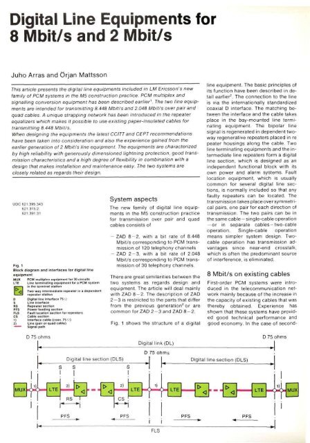
Fig. 1<br />
Block diagram <strong>and</strong> interfaces <strong>for</strong> digital line<br />
equipment<br />
MUX PCM multiplex equipment tor 30 circuits<br />
LTE Line terminating equipment lor a PCM system<br />
In the terminal station<br />
Two-way intermediate repeater in a dependent<br />
repeater station<br />
D Digital line interface 75 Q<br />
S Line Interface<br />
RS Repeater section<br />
PFS Power feeding section<br />
FLS Fault location section <strong>for</strong> repeaters<br />
CS Cable section<br />
1) Interface cable (coax. 75 Q)<br />
2) Line (pair or quad cable)<br />
~ ~ Signal path<br />
System aspects<br />
The new family <strong>of</strong> digital line equipments<br />
in the M5 construction practice<br />
<strong>for</strong> transmission over pair <strong>and</strong> quad<br />
cables consists <strong>of</strong><br />
- ZAD 8-2, with a bit rate <strong>of</strong> 8.448<br />
Mbit/s corresponding to PCM transmission<br />
<strong>of</strong> 120 telephony channels<br />
- ZAD 2-3, with a bit rate <strong>of</strong> 2.048<br />
Mbit/s corresponding to PCM transmission<br />
<strong>of</strong> 30 telephony channels.<br />
There are great similarities between the<br />
two systems as regards design <strong>and</strong><br />
equipment. The article will deal mainly<br />
with ZAD 8-2. The description <strong>of</strong> ZAD<br />
2 — 3 is restricted to the parts that differ<br />
from the previous generation 2 or are<br />
common <strong>for</strong> ZAD 2 - 3 <strong>and</strong> ZAD 8-2.<br />
Fig. 1 shows the structure <strong>of</strong> a digital<br />
line equipment. The basic principles <strong>of</strong><br />
its function have been described in detail<br />
earlier 2 . The connection to the line<br />
is via the internationally st<strong>and</strong>ardized<br />
coaxial D interface. The matching between<br />
the interface <strong>and</strong> the cable takes<br />
place in the bay-mounted line terminating<br />
equipment. The bipolar line<br />
signal is regenerated in dependent twoway<br />
regenerative repeaters placed in re<br />
peater housings along the cable. Two<br />
line terminating equipments <strong>and</strong> the intermediate<br />
line repeaters <strong>for</strong>m a digital<br />
line section, which is designed as an<br />
independent functional block with its<br />
own power <strong>and</strong> alarm systems. Fault<br />
location equipment, which is usually<br />
common <strong>for</strong> several digital line sections,<br />
is normally included so that any<br />
faulty repeaters can be located. The<br />
transmission takes place over symmetrical<br />
pairs, one pair <strong>for</strong> each direction <strong>of</strong><br />
transmission. The two pairs can be in<br />
the same cable — single-cable operation<br />
— or in separate cables —two-cable<br />
operation. Single-cable operation<br />
means simpler system design. Twocable<br />
operation has transmission advantages<br />
since near-end crosstalk,<br />
which is <strong>of</strong>ten the predominant source<br />
<strong>of</strong> interference, is eliminated.<br />
8 Mbit/s on existing cables<br />
First-order PCM systems were introduced<br />
in the telecommunication network<br />
mainly because <strong>of</strong> the increase in<br />
the capacity <strong>of</strong> existing cables that was<br />
thereby obtained. Experience has<br />
shown that these systems have provided<br />
good technical per<strong>for</strong>mance <strong>and</strong><br />
good economy. In the case <strong>of</strong> second-


