

Selection and Testing of Electronic Components for LM
Selection and Testing of Electronic Components for LM
Selection and Testing of Electronic Components for LM

Create successful ePaper yourself
Turn your PDF publications into a flip-book with our unique Google optimized e-Paper software.
Fig. 10<br />
Automatic changeover between two systems that<br />
operate as the working <strong>and</strong> st<strong>and</strong>by system<br />
respectively. The changeover is initiated by the<br />
absence <strong>of</strong> a signal in the receive direction or too<br />
high an error rate on the received signal<br />
Line terminating equipment, system 1<br />
Two-way dependent repeater<br />
Control logic<br />
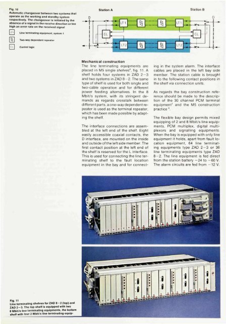
Fig. 11<br />
Line terminating shelves <strong>for</strong> ZAD 8-2 (top) <strong>and</strong><br />
ZAD 2-3. The top shelf is equipped with two<br />
8 Mbit/s line terminating equipments, the bottom<br />
shelf with four 2 Mbit/s line terminating equip-<br />
Mechanical construction<br />
The line terminating equipments are<br />
placed in M5 single shelves", fig. 11. A<br />
shelf holds four systems in ZAD 2-3<br />
<strong>and</strong> two systems in ZAD 8-2. The same<br />
type <strong>of</strong> shelf is used <strong>for</strong> both single <strong>and</strong><br />
two-cable operation <strong>and</strong> <strong>for</strong> different<br />
power feeding alternatives. In the 8<br />
Mbit/s system, with its stringent dem<strong>and</strong>s<br />
as regards crosstalk between<br />
different parts, a one-way dependent repeater<br />
is used as the terminal repeater,<br />
which has been made possible by adapting<br />
the shelf.<br />
The interface connections are assembled<br />
at the left end <strong>of</strong> the shelf. Eight<br />
easily accessible coaxial contacts, the<br />
D interface, are mounted on the inside<br />
<strong>and</strong> outside <strong>of</strong> the left side member. The<br />
first contact position at the left end <strong>of</strong><br />
the shelf is reserved <strong>for</strong> the L interface.<br />
This is used <strong>for</strong> connecting the line terminating<br />
shelf to the fault location<br />
equipment in the bay <strong>and</strong> <strong>for</strong> connect<br />
ing in the system alarm. The interface<br />
cables are placed in the left bay side<br />
member. The station cable is brought<br />
in to the following contact positions in<br />
the shelf via connection units.<br />
As regards the bay construction reference<br />
should be made to the description<br />
<strong>of</strong> the 30 channel PCM terminal<br />
equipment 1 <strong>and</strong> the M5 construction<br />
practice 4 .<br />
The flexible bay design permits mixed<br />
equipping <strong>of</strong> 2 <strong>and</strong> 8 Mbit/s line equipments,<br />
PCM multiplex, digital multiplexors<br />
<strong>and</strong> signalling equipments.<br />
When the bay is equipped with only line<br />
equipment it holds, apart from fault location<br />
equipment, 64 line terminating<br />
equipments type ZAD 2 — 3 or 36<br />
line terminating equipments type ZAD<br />
8-2. The line equipment is fed direct<br />
from the station battery -24 to -60 V.<br />
The alarm circuits are fed from —12 V.


