

Selection and Testing of Electronic Components for LM
Selection and Testing of Electronic Components for LM
Selection and Testing of Electronic Components for LM

Create successful ePaper yourself
Turn your PDF publications into a flip-book with our unique Google optimized e-Paper software.
PE insulated, solid cable<br />
10-pair 10-pair<br />
groups. groups.<br />
St<strong>and</strong>ard |aid up in cross<br />
deviation. |ayers str<strong>and</strong>ed<br />
.1, <strong>of</strong> the (2 + 8)<br />
mutual<br />
capacitance.<br />
percentage 1.4 0.75<br />
Table 1<br />
Near-end crosstalk 25-pair 10-pair<br />
at 1 MHz groups groups<br />
m o m o<br />
dB dB dB dB<br />
Within groups 63 6 58 6<br />
Between adjacent<br />
groups 80 6 68 6<br />
Between groups separated<br />
by one group 97 6.6 78 6<br />
dB dB<br />
Far-end crosstalk<br />
at 150 kHz<br />
RMS 78 70<br />
Table 2<br />
Typical crosstalk values <strong>for</strong> cross str<strong>and</strong>ed cables<br />
m Mean value<br />
a St<strong>and</strong>ard deviation<br />
RMS Root mean square<br />
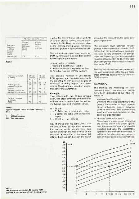
Fig. 14<br />
The number <strong>of</strong> permissible 30-channel PCM<br />
systems, N, can be read <strong>of</strong>f from the diagram <strong>for</strong><br />
cr-value <strong>for</strong> conventional cables with 10<br />
or 25-pair groups laid up in concentric<br />
layers is 8 - 10 dB <strong>and</strong>, as shown in table<br />
2, the corresponding value <strong>for</strong> cross<br />
str<strong>and</strong>ed groups in approximately 6 dB.<br />
The suitability <strong>of</strong> a particular cable <strong>for</strong><br />
PCM transmission is dependent on the<br />
following four parameters:<br />
m Mean value, crosstalk<br />
a St<strong>and</strong>ard deviation, crosstalk<br />
L Attenuation over a repeater section<br />
N Possible number <strong>of</strong> PCM systems<br />
The possible number <strong>of</strong> 30-channel<br />
PCM systems can be determined with<br />
the aid <strong>of</strong> fig. 14 with a certain degree <strong>of</strong><br />
statistical reliability at given m, L <strong>and</strong> a<br />
values. The diagram is based on singlefrequency<br />
measurements.<br />
Example<br />
Two cables with two 10-pair groups<br />
each, one cross str<strong>and</strong>ed <strong>and</strong> the other<br />
with concentric layers, have the following<br />
typical near-end crosstalk values.<br />
m = 68 dB<br />
a = 6 dB <strong>for</strong> the cross str<strong>and</strong>ed cable<br />
a = 9 dB <strong>for</strong> the cable with concentric<br />
layers<br />
L = 29dB(m - L =39 dB)<br />
Fig. 14 shows that the cable with o = 6<br />
dB can be filled (10 systems) whereas<br />
the second cable permits only one<br />
system although the mean value <strong>of</strong> the<br />
crosstalk attenuation is the same (68<br />
dB) <strong>for</strong> both. As can be seen the lower<br />
111<br />
spread <strong>of</strong> the cross str<strong>and</strong>ed cable is <strong>of</strong><br />
great importance.<br />
The crosstalk level between 10-pair<br />
groups in cross str<strong>and</strong>ed cable is 10 dB<br />
better than the level within groups <strong>and</strong><br />
this ratio is very constant. For groups<br />
separated by one group there is an additional<br />
improvement <strong>of</strong> 10 dB. In the case<br />
<strong>of</strong> 25-pair groups the corresponding difference<br />
is 17 dB.<br />
These good <strong>and</strong> well defined values <strong>and</strong><br />
the well organized cable lay-up make<br />
cross str<strong>and</strong>ed cables very suitable <strong>for</strong><br />
PCM systems.<br />
Summary<br />
The method <strong>and</strong> machines <strong>for</strong> telecommunication<br />
manufacture which<br />
have been described above have resulted<br />
in<br />
— improved cable quality<br />
Owing to the cross str<strong>and</strong>ing <strong>of</strong> the<br />
groups the number <strong>of</strong> high capacitance<br />
unbalance values between<br />
pairs is reduced. The capacitance<br />
level <strong>and</strong> st<strong>and</strong>ard deviation <strong>of</strong> the<br />
cable are also reduced.<br />
- reduced production costs<br />
Since twinning <strong>and</strong> group str<strong>and</strong>ing<br />
are carried out in one single operation,<br />
the amount <strong>of</strong> space required is<br />
reduced <strong>and</strong> also the investment,<br />
operation <strong>and</strong> maintenance costs. In<br />
addition the planning <strong>and</strong> supervision<br />
<strong>of</strong> the production are simplified.


