

Selection and Testing of Electronic Components for LM
Selection and Testing of Electronic Components for LM
Selection and Testing of Electronic Components for LM

You also want an ePaper? Increase the reach of your titles
YUMPU automatically turns print PDFs into web optimized ePapers that Google loves.
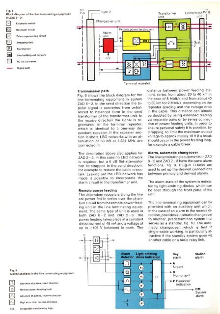
Fig. 8<br />
Block diagram <strong>of</strong> the line terminating equipment<br />
inZAD8-2<br />
<strong>Electronic</strong> switch<br />
Resonant circuit<br />
Pulse regenerating circuit<br />
Strapping field<br />
Trans<strong>for</strong>mer<br />
Line bullding-out network<br />
DC-DC converter<br />
Signal path<br />
Fig. 9<br />
Alarm functions in the line terminating equipment<br />
Absence <strong>of</strong> pulses, send direction<br />
Remote power feeding fault<br />
Absence <strong>of</strong> pulses, receive direction<br />
High error rate, receive direction<br />
Strappable combinatory logic<br />
Transmission path<br />
Fig. 8 shows the block diagram <strong>for</strong> the<br />
line terminating equipment in system<br />
ZAD 8-2. In the send direction the bipolar<br />
signal is converted from unbalanced<br />
to balanced <strong>for</strong>m in the send<br />
trans<strong>for</strong>mer <strong>of</strong> the trans<strong>for</strong>mer unit. In<br />
the receive direction the signal is regenerated<br />
in the terminal repeater,<br />
which is identical to a one-way dependent<br />
repeater. If the repeater section<br />
is short, LBO networks with an attenuation<br />
<strong>of</strong> 30 dB at 4.224 MHz are<br />
connected in.<br />
The description above also applies <strong>for</strong><br />
ZAD 2-3. In this case no LBO network<br />
is required, but a 6 dB flat attenuator<br />
can be strapped in the send direction,<br />
<strong>for</strong> example to reduce the cable crosstalk.<br />
Leaving out the LBO network has<br />
made it possible to incorporate the<br />
alarm circuit in the trans<strong>for</strong>mer unit.<br />
Remote power feeding<br />
The dependent repeaters along the line<br />
are power fed in series over the phantom<br />
circuit from the remote power feeding<br />
unit in the line terminating equipment.<br />
The same type <strong>of</strong> unit is used in<br />
both ZAD 8-2 <strong>and</strong> ZAD 2-3. The<br />
power feeding takes place at a constant<br />
direct current <strong>of</strong> 48 mA <strong>and</strong> a voltage <strong>of</strong><br />
up to ±106 V balanced to earth. The<br />
distance between power feeding stations<br />
varies from about 20 to 40 km in<br />
the case <strong>of</strong> 8 Mbit/s <strong>and</strong> from about 40<br />
to 60 km <strong>for</strong> 2 Mbit/s, depending on the<br />
repeater spacing <strong>and</strong> the voltage drop<br />
in the cable. This distance can almost<br />
be doubled by using extended feeding<br />
via separate pairs or by series connection<br />
<strong>of</strong> power feeding units. In order to<br />
ensure personal safety it is possible, by<br />
strapping, to limit the maximum output<br />
voltage to approximately 10 V if a break<br />
should occur in the powerfeeding loop,<br />
<strong>for</strong> example a cable break.<br />
Alarm, automatic changeover<br />
The line terminating equipments in ZAD<br />
8-2 <strong>and</strong> ZAD 2-3 have the same alarm<br />
functions, fig. 9. Plug-in U-links are<br />
used to set up the desired connections<br />
between primary <strong>and</strong> derived alarms.<br />
The alarm state <strong>of</strong> the system is indicated<br />
by light-emitting diodes, which can<br />
be seen through the front plate <strong>of</strong> the<br />
unit.<br />
The line terminating equipment can be<br />
provided with an auxiliary unit which,<br />
in the case <strong>of</strong> an alarm in the receive direction,<br />
provides automatic changeover<br />
to another, predetermined system that<br />
serves as a st<strong>and</strong>by, fig. 10. The automatic<br />
changeover, which is tied to<br />
single-cable working, is particularly attractive<br />
if the st<strong>and</strong>by system goes via<br />
another cable or a radio relay link.


