

Selection and Testing of Electronic Components for LM
Selection and Testing of Electronic Components for LM
Selection and Testing of Electronic Components for LM

Create successful ePaper yourself
Turn your PDF publications into a flip-book with our unique Google optimized e-Paper software.
Fig. 5<br />
ALBO network <strong>for</strong> automatic equalization <strong>of</strong><br />
0-25 dB (4.224 MHz) pair cable. The variable<br />
resistance R is controlled by the peak amplitude<br />
<strong>of</strong> the signal after the equalization<br />
Vf+0.6f<br />
characteristic<br />
vT characteristic<br />
Fig. 6<br />
Strappable correction network <strong>and</strong> its frequency<br />
characteristic<br />
a) network configuration<br />
b) attenuation<br />
The network can be strapped to compensate <strong>for</strong> all cable<br />
attenuations <strong>of</strong> the <strong>for</strong>m Ad=\T+af where (K-a^-0.6<br />
I.e. the cable parameters 3 can be selected independent<br />
<strong>of</strong> each other<br />
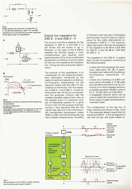
Fig. 4<br />
Block diagram <strong>of</strong> the 8 Mbit/s digital repeater<br />
<strong>and</strong> the associated signal diagram<br />
Digital line repeaters <strong>for</strong><br />
ZAD8-2<strong>and</strong>ZAD2-3<br />
The function <strong>and</strong> block diagram <strong>for</strong> the<br />
repeaters in ZAD 8-2 <strong>and</strong> ZAD 2-3<br />
are similar <strong>and</strong> are shown in fig. 4.<br />
However, in the case <strong>of</strong> the 8 Mbit/s<br />
repeater the detailed design is more<br />
comprehensive <strong>and</strong> requires more<br />
space because <strong>of</strong> the more complicated<br />
equalization conditions. Common tasks<br />
<strong>for</strong> the two line repeaters are equalization,<br />
timing recovery <strong>and</strong> pulse regeneration.<br />
The purpose <strong>of</strong> the equalization is to<br />
compensate <strong>for</strong> the frequency-dependent<br />
attenuation introduced by the<br />
cable. An optimum selection <strong>of</strong> attenuation/frequency<br />
characteristic <strong>for</strong> the<br />
equalizer means that the effect <strong>of</strong> disturbance<br />
is minimized. The line repeaters<br />
in ZAD 8-2 <strong>and</strong> ZAD 2-3 were dimensioned<br />
with the aid <strong>of</strong> a computer,<br />
<strong>and</strong> the goodness criterion was the<br />
smallest possible signal/noise ratio at<br />
the repeater input, i.e. maximum number<br />
<strong>of</strong> disturbing systems <strong>for</strong> a given<br />
bit error rate. For the purpose <strong>of</strong> dimensioning<br />
it was assumed that the line<br />
signal code was one <strong>of</strong> the internationally<br />
st<strong>and</strong>ardized transmission codes,<br />
HDB-3orAMI, <strong>and</strong> that the disturbances<br />
had crosstalk characteristics. The effect<br />
<strong>of</strong> thermal noise has been investigated<br />
<strong>and</strong> has been found to have no significance<br />
<strong>for</strong> the cable attenuations encountered<br />
in ZAD 8-2. The maximum<br />
cable attenuation that can be equalized<br />
in the repeaters is 65 dB at 4.224 MHz<br />
<strong>for</strong> ZAD 8-2 <strong>and</strong> 35 dB at 1.024 MHz<br />
<strong>for</strong> ZAD 2-3.<br />
The repeaters in the ZAD 8-2 system<br />
each contain an equalizer consisting <strong>of</strong><br />
the following parts:<br />
— a fixed part that equalizes the maximum<br />
attenuation 65 dB <strong>of</strong> paperinsulated<br />
pair cable with the attenuation/frequency<br />
characteristic Vf~+<br />
0.6 f.<br />
— a fixed line building-out (LBO) network<br />
which simulates a 15 dB cable<br />
(at 4.224 MHz) <strong>and</strong> which can be connected<br />
in <strong>for</strong> short repeater sections.<br />
— a variable equalizer (ALBO) network<br />
<strong>for</strong> 0-25 dB cable (at 4.224 MHz).<br />
— a strappable network which can be<br />
used to adapt the equalization to different<br />
types <strong>of</strong> paper <strong>and</strong> polytheneinsulated<br />
cable.<br />
The configuration <strong>of</strong> the last two <strong>of</strong><br />
these networks are shown in figs. 5 <strong>and</strong><br />
6. This equalizer design means that line<br />
equipment ZAD 8-2 can be adapted <strong>for</strong><br />
use with all pair <strong>and</strong> quad cables en-


